Table of Contents
Advertisement
Quick Links
www.ti.com
EVM User's Guide: ADS1278V2EVM-PDK
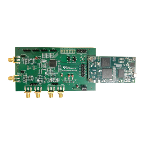
ADS1278EVM-PDK Evaluation Module
Description
The
ADS1278
evaluation module (EVM) is a platform
for evaluating the performance of the ADS1278,
which is a 24-bit, 8-channel simultaneous-sampling
delta-sigma (ΔΣ) analog-to-digital converter (ADC).
The ADS1278 combines high-precision industrial
measurement with excellent dc and ac specifications,
providing a usable signal bandwidth of up to 90% of
the Nyquist rate with less than 0.005dB of passband
ripple. The ADS1278 EVM eases the evaluation of
the device with hardware, software, and computer
connectivity through the universal serial bus (USB)
interface.
Get Started
1. Order the EVM from ti.com.
2. Download the latest software from
PDK.
3. Launch the ADS1278 EVM GUI from the start
menu.
4. Power the ADS1278 EVM from a 6V supply.
5. Connect the ADS1278 EVM to the PHI controller
board and connect the PHI board to the computer
running the ADS1278 EVM GUI.
SBAU436 – JANUARY 2024
Submit Document Feedback
Features
•
Hardware and software required for diagnostic
testing as well as accurate performance evaluation
of the ADS1278
•
The PHI controller provides a convenient
communication interface to the ADS1278 over
USB 2.0 (or higher) for digital input and output
•
Easy-to-use evaluation software for 64-bit
Microsoft
•
The software suite includes graphical tools for data
capture, histogram analysis, and spectral analysis.
This suite also has a provision for exporting data to
a text file for post-processing
Applications
•
Vibration/modal analysis
•
Multi-channel data acquisition
ADS1278EVM-
•
Acoustics/dynamic strain gauges
•
Pressure sensors
Copyright © 2024 Texas Instruments Incorporated
®
Windows
®
10 operating system
ADS1278EVM-PDK Evaluation Module
Description
1
Advertisement
Table of Contents

Related Manuals for Texas Instruments ADS1278V2EVM-PDK


Summary of Contents for Texas Instruments ADS1278V2EVM-PDK
- Page 1 4. Power the ADS1278 EVM from a 6V supply. 5. Connect the ADS1278 EVM to the PHI controller board and connect the PHI board to the computer running the ADS1278 EVM GUI. SBAU436 – JANUARY 2024 ADS1278EVM-PDK Evaluation Module Submit Document Feedback Copyright © 2024 Texas Instruments Incorporated...
-
Page 2: Kit Contents
Likewise, monitoring the analog input signals and power supply rails is supported using the test points built into the board. ADS1278EVM-PDK Evaluation Module SBAU436 – JANUARY 2024 Submit Document Feedback Copyright © 2024 Texas Instruments Incorporated... -
Page 3: Device Information
The device is fully specified over the extended industrial range (–40°C to +105°C) and is available in an HTQFP-64 PowerPAD™ package. SBAU436 – JANUARY 2024 ADS1278EVM-PDK Evaluation Module Submit Document Feedback Copyright © 2024 Texas Instruments Incorporated... - Page 4 SMA input circuits on channels 1 and 2 except the negative inputs are grounded as shown in Figure 2-1. ADS1278EVM-PDK Evaluation Module SBAU436 – JANUARY 2024 Submit Document Feedback Copyright © 2024 Texas Instruments Incorporated...
- Page 5 OUT- 470pF 1000pF OUT+ 0.01uF /THSPD 10.0 AINP1 15.0 1.00k CHAN_N1 VCOM VOCM 220pF THS4551IRUNR 270pF 470pF 1.00k Figure 2-3. Input Drive Amplifier Circuit SBAU436 – JANUARY 2024 ADS1278EVM-PDK Evaluation Module Submit Document Feedback Copyright © 2024 Texas Instruments Incorporated...
- Page 6 CHAN_P8 AINP8 TEST1 1.00k CHAN_N8 AINN8 TEST0 AGND AGND AGND AGND AGND DGND DGND DGND DGND PowerPAD ADS1278IPAPR Figure 2-5. ADS1278 Connections and Decoupling ADS1278EVM-PDK Evaluation Module SBAU436 – JANUARY 2024 Submit Document Feedback Copyright © 2024 Texas Instruments Incorporated...
-
Page 7: Digital Interfaces
100k 10.0k CONTROL.FORMAT0 100k 0.1 µF CONTROL.FORMAT1 100k CONTROL.FORMAT2 100k CONTROL.CLKDIV 100k EEPROM_WP TSW-106-07-G-D EVM_ID_SCL EVM_ID_SDA BR24G32FVT-3AGE2 0.1 µF Figure 2-6. Digital Interface Connections SBAU436 – JANUARY 2024 ADS1278EVM-PDK Evaluation Module Submit Document Feedback Copyright © 2024 Texas Instruments Incorporated... - Page 8 VREFN 150nF VREFext 10µF AVDD VREFN OPA2320AQDGKRQ1 47.0 1.00k VOUT TRIM/NR TEMP 100 µF 0.1 µF 10µF REF5025AIDGKT REF5025AIDGKT Figure 2-7. Reference Voltage Circuit ADS1278EVM-PDK Evaluation Module SBAU436 – JANUARY 2024 Submit Document Feedback Copyright © 2024 Texas Instruments Incorporated...
-
Page 9: Clock Sources
PLL to become stuck if the entered frequencies are coerced to the same frequency. If this occurs, then disconnect and reconnect the GUI to reset the PLL. SBAU436 – JANUARY 2024 ADS1278EVM-PDK Evaluation Module Submit Document Feedback Copyright © 2024 Texas Instruments Incorporated... -
Page 10: Power Supplies
0P8V 0P8V 0P4V 0P4V 0P4V 0P2V 0P2V 0P2V 0P1V 0P1V MMSZ5227B-7-F 0P1V 3.6V MMSZ4690T1G 3.6V TPS7A4700RGWR TPS7A4700RGWR TPS7A4700RGWR 5.6V Figure 2-9. Power Supply Circuitry ADS1278EVM-PDK Evaluation Module SBAU436 – JANUARY 2024 Submit Document Feedback Copyright © 2024 Texas Instruments Incorporated... - Page 11 As shown in Figure 3-1, accept the license agreements and follow the on-screen instructions to complete the installation. Figure 3-1. GUI Installation Prompts SBAU436 – JANUARY 2024 ADS1278EVM-PDK Evaluation Module Submit Document Feedback Copyright © 2024 Texas Instruments Incorporated...
- Page 12 As a part of the ADS1278 EVM GUI installation, install the Device Driver as shown in Figure 3-2. Click Next to proceed. Figure 3-2. Device Driver Installation Prompts ADS1278EVM-PDK Evaluation Module SBAU436 – JANUARY 2024 Submit Document Feedback Copyright © 2024 Texas Instruments Incorporated...
- Page 13 LabVIEW run-time engine is not already installed, as shown in Figure 3-3. Figure 3-3. LabVIEW Runtime Installation Prompts SBAU436 – JANUARY 2024 ADS1278EVM-PDK Evaluation Module Submit Document Feedback Copyright © 2024 Texas Instruments Incorporated...
-
Page 14: Hardware Connection
2. Install screws and 3. PHI Indicator LEDs connect USB. 3. Connect 5. Connect Input Power to the Signals ADS1278 EVM Figure 3-4. Hardware Connections ADS1278EVM-PDK Evaluation Module SBAU436 – JANUARY 2024 Submit Document Feedback Copyright © 2024 Texas Instruments Incorporated... - Page 15 Mode and Format Channel Pins Shutdown Pins Vref IN External Clock Digital Vcm out Communica on pins Figure 3-5. Optional EVM Connections SBAU436 – JANUARY 2024 ADS1278EVM-PDK Evaluation Module Submit Document Feedback Copyright © 2024 Texas Instruments Incorporated...
- Page 16 ¡ ¢ Vref se ng Number of samples to capture Clock Se n gs £ Figure 3-6. EVM Settings ADS1278EVM-PDK Evaluation Module SBAU436 – JANUARY 2024 Submit Document Feedback Copyright © 2024 Texas Instruments Incorporated...
- Page 17 Switching pages to any of the analysis tools described in the subsequent sections causes calculations to be performed on the same set of data. Figure 3-7. Time Domain Display SBAU436 – JANUARY 2024 ADS1278EVM-PDK Evaluation Module Submit Document Feedback Copyright © 2024 Texas Instruments Incorporated...
- Page 18 24-bit ADC. The None option corresponds to not using a window (or a rectangular window) and is not recommended. Figure 3-8. Frequency Domain Display ADS1278EVM-PDK Evaluation Module SBAU436 – JANUARY 2024 Submit Document Feedback Copyright © 2024 Texas Instruments Incorporated...
-
Page 19: Histogram Display
As shown in Figure 3-9, the histogram corresponding to a dc input is displayed on clicking the Capture button. Figure 3-9. Histogram Display SBAU436 – JANUARY 2024 ADS1278EVM-PDK Evaluation Module Submit Document Feedback Copyright © 2024 Texas Instruments Incorporated... - Page 20 100k CONTROL.FORMAT0 100k /PWDN5 100k CONTROL.FORMAT1 100k /PWDN6 100k CONTROL.FORMAT2 100k /PWDN7 100k CONTROL.CLKDIV 100k /PWDN8 100k TSW-106-07-G-D TSW-109-07-G-D Figure 4-1. ADS1278 Connections Schematic ADS1278EVM-PDK Evaluation Module SBAU436 – JANUARY 2024 Submit Document Feedback Copyright © 2024 Texas Instruments Incorporated...
- Page 21 PHI_CLK TSM-103-01-L-SV 0.1 µF PHI CLK EVM_ID_SCL SG-210STF27.0000ML0 EVM_ID_SDA Alternate: LMK6CA027000CDLFR TSM-103-01-L-SV BR24G32FVT-3AGE2 0.1 µF OSC DISABLE Figure 4-2. ADS1278 EVM Digital Connections Schematic SBAU436 – JANUARY 2024 ADS1278EVM-PDK Evaluation Module Submit Document Feedback Copyright © 2024 Texas Instruments Incorporated...
- Page 22 TPS7A4700RGWR With CNR set to 2uF 5.6V Start Slope = 58.5V/s Startup m e=119ms ¡ Start Slope = 30.2V/s Figure 4-3. Power Supplies Schematic ADS1278EVM-PDK Evaluation Module SBAU436 – JANUARY 2024 Submit Document Feedback Copyright © 2024 Texas Instruments Incorporated...
- Page 23 VCOM VOCM 220pF 220pF THS4551IRUNR THS4551IRUNR 270pF 270pF AINN4 R120 R121 470pF 470pF R122 1.00k 1.00k R123 R124 Figure 4-4. Driven Input Circuitry Schematic SBAU436 – JANUARY 2024 ADS1278EVM-PDK Evaluation Module Submit Document Feedback Copyright © 2024 Texas Instruments Incorporated...
- Page 24 0.1% 0.1% 220pF 220pF 0.01uF 0.01uF TSW-104-07-G-S TSW-104-07-G-S 220pF 220pF R131 R132 AINN6 AINN8 CHAN_N6 CHAN_N8 0.1% 0.1% Figure 4-5. Undriven Input Circuitry Schematic ADS1278EVM-PDK Evaluation Module SBAU436 – JANUARY 2024 Submit Document Feedback Copyright © 2024 Texas Instruments Incorporated...
- Page 25 Figure 4-6 through Figure 4-11 show the PCB layouts for the ADS1278 EVM. Figure 4-6. Top Side Composite Layout Figure 4-7. Bottom Side Composite Layout SBAU436 – JANUARY 2024 ADS1278EVM-PDK Evaluation Module Submit Document Feedback Copyright © 2024 Texas Instruments Incorporated...
- Page 26 Hardware Design Files www.ti.com Figure 4-8. Top Signal Layer Layout Figure 4-9. Ground Layer Layout ADS1278EVM-PDK Evaluation Module SBAU436 – JANUARY 2024 Submit Document Feedback Copyright © 2024 Texas Instruments Incorporated...
- Page 27 Hardware Design Files Figure 4-10. Power Layer Layout Figure 4-11. Bottom Signal Layer Layout SBAU436 – JANUARY 2024 ADS1278EVM-PDK Evaluation Module Submit Document Feedback Copyright © 2024 Texas Instruments Incorporated...
- Page 28 CAP, CERM, 0.01 uF, 25 V, +/- 5%, C0G/NP0, 0.01uF 0603 C0603H103J3GACTU Kemet C85, C86, C91, C92 0603 CAPCLK, MCLKo Test Point, SMT Test Point, SMT S2751-46R Harwin ADS1278EVM-PDK Evaluation Module SBAU436 – JANUARY 2024 Submit Document Feedback Copyright © 2024 Texas Instruments Incorporated...
- Page 29 RES, 0, 5%, 0.063 W, AEC-Q200 Grade 0, R18, R20, R22 0402 CRCW04020000Z0ED Vishay-Dale 0402 RES, 1.00 k, 1%, 0.063 W, AEC-Q200 Grade R19, R23 1.00k 0402 CRCW04021K00FKED Vishay-Dale 0, 0402 SBAU436 – JANUARY 2024 ADS1278EVM-PDK Evaluation Module Submit Document Feedback Copyright © 2024 Texas Instruments Incorporated...
- Page 30 HTQFP64 ADS1278IPAPR Texas Instruments to-Digital Converters Automotive Qualified Precision, Zero- Crossover, 20MHz, 0.9pA Ib, RRIO, CMOS DGK0008A OPA2320AQDGKRQ1 Texas Instruments Operational Amplifier, DGK0008A (VSSOP-8) ADS1278EVM-PDK Evaluation Module SBAU436 – JANUARY 2024 Submit Document Feedback Copyright © 2024 Texas Instruments Incorporated...
- Page 31 R71, R72, R83, R86, R95, R96, R97, R98, RES, 0, 5%, 0.1 W, AEC-Q200 Grade 0, 0603 0603 CRCW06030000Z0EA Vishay-Dale R110, R112, R123, R124 SBAU436 – JANUARY 2024 ADS1278EVM-PDK Evaluation Module Submit Document Feedback Copyright © 2024 Texas Instruments Incorporated...
-
Page 32: Additional Information
Additional Information www.ti.com 5 Additional Information 5.1 Trademarks LabVIEW ™ is a trademark of Texas Instruments. Microsoft ® and Windows ® are registered trademarks of Microsoft Corporation. All trademarks are the property of their respective owners. 6 References • Texas Instruments,... - Page 33 STANDARD TERMS FOR EVALUATION MODULES Delivery: TI delivers TI evaluation boards, kits, or modules, including any accompanying demonstration software, components, and/or documentation which may be provided together or separately (collectively, an “EVM” or “EVMs”) to the User (“User”) in accordance with the terms set forth herein.
- Page 34 www.ti.com Regulatory Notices: 3.1 United States 3.1.1 Notice applicable to EVMs not FCC-Approved: FCC NOTICE: This kit is designed to allow product developers to evaluate electronic components, circuitry, or software associated with the kit to determine whether to incorporate such items in a finished product and software developers to write software applications for use with the end product.
- Page 35 www.ti.com Concernant les EVMs avec antennes détachables Conformément à la réglementation d'Industrie Canada, le présent émetteur radio peut fonctionner avec une antenne d'un type et d'un gain maximal (ou inférieur) approuvé pour l'émetteur par Industrie Canada. Dans le but de réduire les risques de brouillage radioélectrique à...
- Page 36 www.ti.com EVM Use Restrictions and Warnings: 4.1 EVMS ARE NOT FOR USE IN FUNCTIONAL SAFETY AND/OR SAFETY CRITICAL EVALUATIONS, INCLUDING BUT NOT LIMITED TO EVALUATIONS OF LIFE SUPPORT APPLICATIONS. 4.2 User must read and apply the user guide and other available documentation provided by TI regarding the EVM prior to handling or using the EVM, including without limitation any warning or restriction notices.
- Page 37 Notwithstanding the foregoing, any judgment may be enforced in any United States or foreign court, and TI may seek injunctive relief in any United States or foreign court. Mailing Address: Texas Instruments, Post Office Box 655303, Dallas, Texas 75265 Copyright © 2023, Texas Instruments Incorporated...
- Page 38 TI products. TI’s provision of these resources does not expand or otherwise alter TI’s applicable warranties or warranty disclaimers for TI products. TI objects to and rejects any additional or different terms you may have proposed. IMPORTANT NOTICE Mailing Address: Texas Instruments, Post Office Box 655303, Dallas, Texas 75265 Copyright © 2024, Texas Instruments Incorporated...
Need help?
Do you have a question about the ADS1278V2EVM-PDK and is the answer not in the manual?
Questions and answers