Table of Contents
Advertisement
Quick Links
ADS1178EVM, ADS1278EVM, ADS1178EVM-PDK, and
This user's guide describes the characteristics, operation, and use of the ADS1178EVM and
ADS1278EVM, both by themselves and as part of the ADS1178EVM-PDK or ADS1278EVM-PDK. These
evaluation modules (EVMs) are evaluation boards for the ADS1278, a 24-bit multi-channel, delta-sigma
analog-to-digital converter (ADC), and the ADS1178, a 16-bit version of the ADS1278. The EVM allows
evaluation of all aspects of the ADS1178 or ADS1278 device. Complete circuit descriptions, schematic
diagrams, and bills of material are included in this document.
The following related documents are available through the Texas Instruments web site at
http://www.ti.com.
Device
ADS1278
REF5025
REF3125
OPA2350
ADS1178
ADCPro is a trademark of Texas Instruments.
Microsoft, Windows are registered trademarks of Microsoft Corporation.
2
I
C is a trademark of NXP Semiconductors, Inc.
All other trademarks are the property of their respective owners.
SBAU129C – November 2007 – Revised July 2008
Submit Documentation Feedback
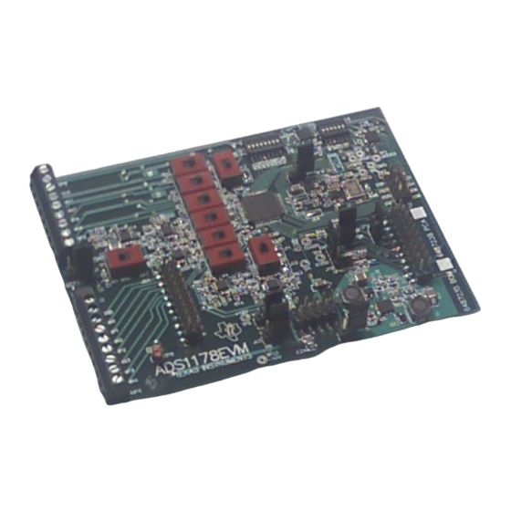
ADS1178EVM (Left) and ADS1178EVM-PDK (Right)
EVM-Compatible Device Data Sheets
Literature Number
SBAS367A
SBOS410
SBVS046C
SBOS099C
SBAS373A
ADS1178EVM, ADS1278EVM, ADS1178EVM-PDK, and ADS1278EVM-PDK
SBAU129C – November 2007 – Revised July 2008
ADS1278EVM-PDK
Device
Literature Number
OPA1632
SBOS286A
SN74LVC2G157
SCES207K
TPS73018
SBVS054H
TPS65131
SLVS493B
PCA9535
SCPS129H
User's Guide
1
Advertisement
Table of Contents

Related Manuals for Texas Instruments ADS1178EVM


Summary of Contents for Texas Instruments ADS1178EVM
- Page 1 ADS1278EVM-PDK ADS1178EVM (Left) and ADS1178EVM-PDK (Right) This user's guide describes the characteristics, operation, and use of the ADS1178EVM and ADS1278EVM, both by themselves and as part of the ADS1178EVM-PDK or ADS1278EVM-PDK. These evaluation modules (EVMs) are evaluation boards for the ADS1278, a 24-bit multi-channel, delta-sigma analog-to-digital converter (ADC), and the ADS1178, a 16-bit version of the ADS1278.
-
Page 2: Table Of Contents
J8: Supplemental Analog Interface Pinout ..................... J5: Serial Interface Pins ..................J3 Configuration: Power-Supply Input ......................J15 +10V Selection ......................J16 –10V Selection ......................List of Switches ADS1178EVM, ADS1278EVM, ADS1178EVM-PDK, and ADS1278EVM-PDK SBAU129C – November 2007 – Revised July 2008 Submit Documentation Feedback... - Page 3 ..................Operating Modes: Clock Frequency ................... ADS1278EVM Bill of Materials SBAU129C – November 2007 – Revised July 2008 ADS1178EVM, ADS1278EVM, ADS1178EVM-PDK, and ADS1278EVM-PDK Submit Documentation Feedback...
-
Page 4: Evm Overview
• Complete control of board settings • Easily expandable with new analysis plug-in tools from Texas Instruments For use with a computer, the ADS1178EVM-PDK or ADS1278EVM-PDK is available. This kit combines the ADS1178EVM/ADS1278EVM board with the DSP-based MMB0 motherboard, and includes ADCPro™... -
Page 5: Digital Interface
J5. This header/socket provides access to the digital control and serial data pins of the ADC. Consult Samtec at http://www.samtec.com or call 1-800-SAMTEC-9 for a variety of mating connector options. SBAU129C – November 2007 – Revised July 2008 ADS1178EVM, ADS1278EVM, ADS1178EVM-PDK, and ADS1278EVM-PDK Submit Documentation Feedback... -
Page 6: J5: Serial Interface Pins
ADS1278EVM-PDK to read back and display all the channels. All the data output signals (DOUT1 to DOUT8) can be monitored on J2. Figure 1 illustrates the pinout for J2. ADS1178EVM, ADS1278EVM, ADS1178EVM-PDK, and ADS1278EVM-PDK SBAU129C – November 2007 – Revised July 2008 Submit Documentation Feedback... -
Page 7: Power Supplies
10V to 15V. The onboard voltage is always 10V. Table 5 Table 6 list the options for J15 and J16, respectively. Figure 2 shows the pinout for connectors J15 and J16. SBAU129C – November 2007 – Revised July 2008 ADS1178EVM, ADS1278EVM, ADS1178EVM-PDK, and ADS1278EVM-PDK Submit Documentation Feedback... -
Page 8: Voltage Reference
J9. Figure 3 illustrates the pinout for connector J1. Figure 4 shows switch S1 as it appears on the EVM. Figure 3. Connector J1 ADS1178EVM, ADS1278EVM, ADS1178EVM-PDK, and ADS1278EVM-PDK SBAU129C – November 2007 – Revised July 2008 Submit Documentation Feedback... -
Page 9: Power-Down, Mode, And Format Control
TOUT connection or having an external clock source connected to J18. The same condition is true if frequencies other than the 27MHz provided by the onboard oscillator must be investigated. SBAU129C – November 2007 – Revised July 2008 ADS1178EVM, ADS1278EVM, ADS1178EVM-PDK, and ADS1278EVM-PDK Submit Documentation Feedback... -
Page 10: Evm Operation
Terminal Block (TBK) or towards the ADS1278 to select the Amplifier (AMP) for the analog inputs 1 through 8, as shown in Figure ADS1178EVM, ADS1278EVM, ADS1178EVM-PDK, and ADS1278EVM-PDK SBAU129C – November 2007 – Revised July 2008 Submit Documentation Feedback... -
Page 11: Amplifier Selection Switches
DSP or microcontroller interface board, such as the 5-6KINTERFACE or HPA-MCUINTERFACE boards available from Texas Instruments, or the MMB0 if purchased as part of the ADS1278EVM-PDK. For a list of compatible interface and/or accessory boards for the EVM or the ADS1278, see the relevant product folder on the TI web site. - Page 12 +10V and –10V signals. Because the circuitry is provided on the ADS1278EVM to generate +10V and –10V, the complete system can be powered from the supplied AC adapter that supplies +6V and 3A. ADS1178EVM, ADS1278EVM, ADS1178EVM-PDK, and ADS1278EVM-PDK SBAU129C – November 2007 – Revised July 2008 Submit Documentation Feedback...
-
Page 13: Ads1278Evm Default Jumper Locations
Ain1-3 terminal block (amplifiers bypassed) Ain4 terminal block (amplifiers bypassed) Down Ain5 terminal block (amplifiers bypassed) S7-S9 Left Ain6-8 terminal block (amplifiers bypassed) Right Frame-sync format SBAU129C – November 2007 – Revised July 2008 ADS1178EVM, ADS1278EVM, ADS1178EVM-PDK, and ADS1278EVM-PDK Submit Documentation Feedback... -
Page 14: Ads1278Evm-Pdk Kit Operation
The software should now be installed, but the USB drivers may not yet have been loaded by the PC operating system. This step will complete when the ADCPro software is executed; see Section 9.4, Running the Software and Completing Driver Installation. ADS1178EVM, ADS1278EVM, ADS1178EVM-PDK, and ADS1278EVM-PDK SBAU129C – November 2007 – Revised July 2008 Submit Documentation Feedback... -
Page 15: Mmb0 Initial Setup
WALL SUPPL Y CONNECTION BOOT MODE SWITCH CONNECT IF NEEDED. SEE TEXT . POWER SUPPL Y CONFIG Figure 8. MMB0 Initial Setup SBAU129C – November 2007 – Revised July 2008 ADS1178EVM, ADS1278EVM, ADS1178EVM-PDK, and ADS1278EVM-PDK Submit Documentation Feedback... -
Page 16: Connecting Ads1278Evm To Mmb0
EVM). Note that the default configuration for the EVM is to use external ±10V supplies for the input amplifiers. ADS1178EVM, ADS1278EVM, ADS1178EVM-PDK, and ADS1278EVM-PDK SBAU129C – November 2007 – Revised July 2008 Submit Documentation Feedback... -
Page 17: Connecting An Ac Adapter
The MMB0 is a Modular EVM System motherboard. It is designed around the TMS320VC5507, a DSP with an onboard USB interface from Texas Instruments. The MMB0 also has 16MB of SDRAM installed. The MMB0 is not sold as a DSP development board, and it is not available separately. TI cannot offer support for the MMB0 except as part of an EVM kit. -
Page 18: Laboratory Power-Supply Connection
Make sure the ADCPro software and device plug-in software are installed from the CD-ROM as described in Section 9.1, Installing the ADCPro Software. ADS1178EVM, ADS1278EVM, ADS1178EVM-PDK, and ADS1278EVM-PDK SBAU129C – November 2007 – Revised July 2008 Submit Documentation Feedback... -
Page 19: Ni-Visa Driver Installation
12, it is not necessary to search for the software; it has already been installed to your PC. • For the remaining steps, accept the default settings. Figure 12. NI-VISA Driver Installation SBAU129C – November 2007 – Revised July 2008 ADS1178EVM, ADS1278EVM, ADS1178EVM-PDK, and ADS1278EVM-PDK Submit Documentation Feedback... -
Page 20: Ni-Visa Driver Installation Question
ADS1278EVM-PDK Kit Operation www.ti.com Figure 13. NI-VISA Driver Installation Question Figure 14. NI-VISA Driver Installing ADS1178EVM, ADS1278EVM, ADS1178EVM-PDK, and ADS1278EVM-PDK SBAU129C – November 2007 – Revised July 2008 Submit Documentation Feedback... -
Page 21: Ni-Visa Driver Complete Installation
This should complete the installation of the NI-VISA drivers. You can verify proper installation by opening the Device Manager and locating the driver as shown in Figure Figure 16. NI-VISA Driver Verification Using Device Manager SBAU129C – November 2007 – Revised July 2008 ADS1178EVM, ADS1278EVM, ADS1178EVM-PDK, and ADS1278EVM-PDK Submit Documentation Feedback... -
Page 22: Adcpro Software Start-Up Display Window
1. Start the software by selecting ADCPro from the Windows Start menu. The screen in Figure 17 appears. Figure 17. ADCPro Software Start-up Display Window ADS1178EVM, ADS1278EVM, ADS1178EVM-PDK, and ADS1278EVM-PDK SBAU129C – November 2007 – Revised July 2008 Submit Documentation Feedback... -
Page 23: Ads1278Evm-Pdk Plug-In Display Window
During the driver installation, a message may appear indicating the firmware load has TIMED OUT. Click OK and continue driver installation. The plug-in will attempt to download the firmware again once the driver installation completes. SBAU129C – November 2007 – Revised July 2008 ADS1178EVM, ADS1278EVM, ADS1178EVM-PDK, and ADS1278EVM-PDK Submit Documentation Feedback... -
Page 24: Install New Driver Wizard Screen 1
ADS1278EVM-PDK Kit Operation www.ti.com Figure 19. Install New Driver Wizard Screen 1 Figure 20. Install New Driver Wizard Screen 2 ADS1178EVM, ADS1278EVM, ADS1178EVM-PDK, and ADS1278EVM-PDK SBAU129C – November 2007 – Revised July 2008 Submit Documentation Feedback... -
Page 25: Install New Driver Wizard Screen
ADS1278EVM-PDK Kit Operation www.ti.com Figure 21. Install New Driver Wizard Screen 3 Figure 22. Install New Driver Wizard Screen 4 SBAU129C – November 2007 – Revised July 2008 ADS1178EVM, ADS1278EVM, ADS1178EVM-PDK, and ADS1278EVM-PDK Submit Documentation Feedback... -
Page 26: Install New Driver Wizard Screen 5
Figure 24. USBSytx Driver Verification Using Device Manager The driver installation wizard sequence should not appear again, unless you connect the board to a different USB port. ADS1178EVM, ADS1278EVM, ADS1178EVM-PDK, and ADS1278EVM-PDK SBAU129C – November 2007 – Revised July 2008 Submit Documentation Feedback... -
Page 27: Evaluating Performance With The Adcpro Software
The ADS1278 can acquire data from one to eight channels simultaneously. The ChannelEnable tab (as shown in Figure 25) provides the control to turn each channel on or off. Figure 25. Channel Enable SBAU129C – November 2007 – Revised July 2008 ADS1178EVM, ADS1278EVM, ADS1178EVM-PDK, and ADS1278EVM-PDK Submit Documentation Feedback... -
Page 28: Manual Channel Control
Table Table 8. Operating Modes: Clock Frequency Operating Mode CLKDIV Frequency (MHz) High-Speed 32.768 High-Resolution Low-Power Low-Power 13.5 Low-Speed Low-Speed ADS1178EVM, ADS1278EVM, ADS1178EVM-PDK, and ADS1278EVM-PDK SBAU129C – November 2007 – Revised July 2008 Submit Documentation Feedback... -
Page 29: Clock Settings And Mode
Clock Frequency box once focus has moved from that control. Figure 27. Clock Settings and Mode SBAU129C – November 2007 – Revised July 2008 ADS1178EVM, ADS1278EVM, ADS1178EVM-PDK, and ADS1278EVM-PDK Submit Documentation Feedback... -
Page 30: Output Data Format
Sync, TDM Format, but both Dynamic and Fixed Mode can be selected. Figure 29 shows the output data format options. Figure 29. Output Data Format ADS1178EVM, ADS1278EVM, ADS1178EVM-PDK, and ADS1278EVM-PDK SBAU129C – November 2007 – Revised July 2008 Submit Documentation Feedback... -
Page 31: Progress Bar While Collecting Data
If ADCPro stops responding while the ADS1278EVM-PDK is connected, try unplugging the power supply from the PDK. Unload and reload the plug-in before reapplying power to the PDK. SBAU129C – November 2007 – Revised July 2008 ADS1178EVM, ADS1278EVM, ADS1178EVM-PDK, and ADS1278EVM-PDK Submit Documentation Feedback... -
Page 32: Schematics And Layout
Schematics and Layout www.ti.com Schematics and Layout Schematics for the ADS1178EVM and ADS1278EVM are appended to this user's guide. The bill of materials is provided in Table 11.1 Bill of Materials Note: All components should be compliant with the European Union Restriction on Use of Hazardous Substances (RoHS) Directive. - Page 33 Bus Wire (18-22 Gauge) L1, L2 Inductor, 4.7µH, 1.8A, 6x6mm, SMD EPCOS B82462G4472M S1-S9 Switch, Mini Slide, DPDT SS22SDP2 DIP Switch, Half-Pitch, 8-Position C&K TDA08H0SB1 SBAU129C – November 2007 – Revised July 2008 ADS1178EVM, ADS1278EVM, ADS1178EVM-PDK, and ADS1278EVM-PDK Submit Documentation Feedback...
- Page 34 DIP Switch, Half-Pitch, 6-Position C&K TDA06H0SB1 4PDT Slide Switch, Top Actuator Tyco/Alcoswi MMS42 PCB Test Point, Large Loop, Keystone 5011 Through-Hole Electronics Shorting Blocks Samtec SNT-100-BK-G-H ADS1178EVM, ADS1278EVM, ADS1178EVM-PDK, and ADS1278EVM-PDK SBAU129C – November 2007 – Revised July 2008 Submit Documentation Feedback...
- Page 35 22 uF 16V SEMICONDUCTOR GROUP PGND EPC_B82462-G4472-M 10 nF 6730 SOUTH TUCSON BLVD., TUCSON, AZ 85706 USA AGND PGND 4.7 nF TITLE ENGINEER RUSSELL ANDERSON ADS1178EVM 0.1uF TPS65131RGE DRAWN BY RUSSELL ANDERSON 6487237 DOCUMENT CONTROL NO. SIZE DATE 22-FEB-2008 SHEET FILE...
- Page 36 J9A (TOP) = SAM_TSM-110-01-L-DV-P J9B (BOTTOM) = SAM_SSW-110-22-F-D-VS-K DATA ACQUISITION PRODUCTS HIGH-PERFORMANCE ANALOG DIVISION SEMICONDUCTOR GROUP 6730 SOUTH TUCSON BLVD., TUCSON, AZ 85706 USA TITLE ENGINEER RUSSELL ANDERSON ADS1178EVM DRAWN BY RUSSELL ANDERSON DOCUMENT CONTROL NO. 6487537 SIZE DATE 22-FEB-2008 SHEET...
- Page 43 REVISION HISTORY ENGINEERING CHANGE NUMBER APPROVED REFP AVDD 150nF 10uF AVDD REFN REF3125AIDBZ PCA9535RGE SW-DPDT IOVDD 0.47uF 0.1uF IOVDD AVDD 0.1uF IOVDD 0.1uF DIPSWITCH-6 OPA2350 100K TP11 100uF JPR-1X3 0.1uF 100K DIPSWITCH-8 AVDD IOVDD VOUT 100K TEMP TRIM 10uF REF5025 ADS1278IPAP SYNC CNTL...
- Page 44 REVISION HISTORY ENGINEERING CHANGE NUMBER APPROVED R4 1K R22 1K +10V +10V 1.5nF C0G 1.5nF C0G 0.1uF 0.1uF CHAN-P4 CHAN-P8 49.9 49.9 ANP4 ANP8 VOCM VOCM CHAN-N4 CHAN-N8 49.9 49.9 ANN4 SW-DPDT ANN8 SW-DPDT OPA1632 OPA1632 R8 1K R32 1K VCOM 0.1uF 0.1uF...
- Page 51 EVALUATION BOARD/KIT IMPORTANT NOTICE Texas Instruments (TI) provides the enclosed product(s) under the following conditions: This evaluation board/kit is intended for use for ENGINEERING DEVELOPMENT, DEMONSTRATION, OR EVALUATION PURPOSES ONLY and is not considered by TI to be a finished end-product fit for general consumer use. Persons handling the product(s) must have electronics training and observe good engineering practice standards.
- Page 52 IMPORTANT NOTICE Texas Instruments Incorporated and its subsidiaries (TI) reserve the right to make corrections, modifications, enhancements, improvements, and other changes to its products and services at any time and to discontinue any product or service without notice. Customers should obtain the latest relevant information before placing orders and should verify that such information is current and complete.
Need help?
Do you have a question about the ADS1178EVM and is the answer not in the manual?
Questions and answers