Emerson Rosemount 5600 Series Reference Manual
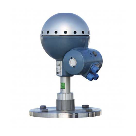
Level transmitter non-contacting radar with hart protocol
Hide thumbs
Also See for Rosemount 5600 Series:
- Quick start manual (24 pages) ,
- Product data sheet (28 pages) ,
- Reference manual (98 pages)

Related Manuals for Emerson Rosemount 5600 Series


Summary of Contents for Emerson Rosemount 5600 Series
- Page 1 Reference Manual 00809-0100-4024, Rev CA March 2020 Rosemount ™ 5600 Series Level Transmitter ® Non-Contacting Radar with HART Protocol...
- Page 3 Reference Manual Title Page 00809-0100-4024, Rev CA March 2020 Rosemount ™ 5600 Series Radar Level Transmitter NOTICE Read this manual before working with the product. For personal and system safety, and for optimum product performance, make sure you thoroughly understand the contents before installing, using, or maintaining this product.
- Page 4 Title Page Reference Manual 00809-0100-4024, Rev CA March 2020 Title Page...
-
Page 5: Table Of Contents
Contents Reference Manual March 2020 00809-0100-5901, Rev CA Table of Contents 1Section 1: Introduction Safety messages ..............9 Overview . - Page 6 Reference Manual Contents 00809-0100-5901, Rev CA March 2020 2.8.5 Mounting the antenna ............39 Mounting the parabolic antenna .
- Page 7 Reference Manual Contents 00809-0100-5901, Rev CA March 2020 4.9.6 Filtering ..............78 5Section 5: HART Configuration Safety messages.
- Page 8 Reference Manual Contents 00809-0100-5901, Rev CA March 2020 BAppendix B: Product Certifications European Directive Information ........... 109 Ordinary Location Certification .
-
Page 9: Safety Messages
Reference Manual Introduction 00809-0100-4024, Rev CA March 2020 Section 1 Introduction Safety messages ..............page 9 Overview . -
Page 10: Overview
Series Radar Level Transmitter. It also describes how to start up and configure the transmitter. The main purpose of the book is to act as guide to installing and operating the Rosemount 5600 Series Radar Level Transmitter. It is not intended to cover service tasks such as changing circuit boards or internal software. - Page 11 00809-0100-4024, Rev CA March 2020 The Rosemount 5600 Series Radar Level Transmitter is a powerful radar level transmitter suitable for non-contact level measurements in process tanks, storage tanks, and other types of tanks. It is designed for easy installation and maintenance free operation.
-
Page 12: Specific Fcc Requirements (Usa Only)
This signal can be measured very accurately allowing fast, reliable, and accurate level measurements. The Rosemount 5600 Series Radar Level Transmitter uses micro frequency to reduce sensitivity to vapor, foam, and contamination of the antenna, and keeps the radar beam narrow in order to minimize influence from walls and disturbing objects. - Page 13 Reference Manual Introduction 00809-0100-4024, Rev CA March 2020 Table 1-1. Categories of Liquids Oil, gasoline and other hydrocarbons, petrochemicals (dielectric constant, =1.9-4.0) Alcohols, concentrated acids, organic solvents, oil/water mixtures and acetone ( =4.0-10) Conductive liquids, e.g. water based solutions, dilute acids, and alkalis ( >...
-
Page 14: Unpacking Your Rosemount 5600 Transmitter
Reference Manual Introduction 00809-0100-4024, Rev CA March 2020 Measuring close to the tank bottom When measuring products with low dielectric constants (i.e. DC range 1.4 - 2.5), some of the radar energy will go thru the product. This could lead to that the radar will see the Flat Tank Bottom, even though there is a small amount of product covering the bottom of the tank. - Page 15 Reference Manual Introduction 00809-0100-4024, Rev CA March 2020 The representative will provide: A Return Material Authorization (RMA) number Instructions and procedures that are necessary to return goods that were exposed to hazardous substances Spare parts Any substitution of non-recognized spare parts may jeopardize safety. Repair (e.g. substitution of components, etc.) may also jeopardize safety and is under no circumstances allowed.
- Page 16 Reference Manual Introduction 00809-0100-4024, Rev CA March 2020 Introduction...
-
Page 17: Safety Messages
Mechanical Installation Reference Manual March 2020 00809-0100-4024, Rev CA Section 2 Mechanical Installation Safety messages ..............page 17 Introduction . - Page 18 Reference Manual Mechanical Installation 00809-0100-4024, Rev CA March 2020 This product is an electrical apparatus and must be installed in the hazardous area in accordance with the requirements of the EC Type Examination Certificate. The installation and maintenance must be carried out in accordance with all appropriate international, national and local standard codes of practice and site regulations for intrinsically safe apparatus and in accordance with the instructions contained within this manual.
-
Page 19: Introduction
2.2.1 Tools The following set of tools are needed for installation of a Rosemount 5600 Series Radar Level Transmitter: Screw driver Adjustable wrench ... - Page 20 Reference Manual Mechanical Installation 00809-0100-4024, Rev CA March 2020 Figure 2-1. Nozzle Requirements, See Table 2-1 Hold Off maximum Distance Ø Table 2-1. Nozzle Requirements in Inches (Millimeters) Antenna Diam Hold off distance recommended maximum Cone 3 in. 3.7 (95) or less 2.9 (75) 9.6 (245) 4.7 (120)
-
Page 21: Free Space Requirements
Reference Manual Mechanical Installation 00809-0100-4024, Rev CA March 2020 2.3.3 Free space requirements Figure 2-3. Free Space Requirements, See Table 2-2 Table 2-2. Free Space Requirements A. Service space width Antenna Distance in. (mm) All antennas 22 (550) B. Service space height Antenna Distance in. -
Page 22: Beam Width
Reference Manual Mechanical Installation 00809-0100-4024, Rev CA March 2020 Table 2-2. Free Space Requirements D. Minimum distance to tank wall Antenna Distance in. (mm) Cone 24 (600) Process seal 24 (600) Parabolic 24 (600) Mounting closer to the tank wall may be allowed if reduced accuracy is accepted. 2.3.4 Beam width Figure 2-4. -
Page 23: Special Antennas And Space Requirements Reference
Reference Manual Mechanical Installation 00809-0100-4024, Rev CA March 2020 Figure 2-5. Beam Width Distance, See Table 2-4 Table 2-4. Beam Width Distance Diameter of radiated area at different distances from flange, ft. (m) Antenna 16 ft (5 m) 33 ft (10 m) 49 ft (15 m) 66 ft (20 m) Cone 3 in. -
Page 24: Wave Guide Tubes
Reference Manual Mechanical Installation 00809-0100-4024, Rev CA March 2020 Wave guide tubes Note The wave guide tubes are parts of the antenna kits. Cone antenna For model codes 1xx, 2xx, 7xx, and 9xx (with PTFE Seal for Cone) Distinguishing features: ... -
Page 25: Mounting The Cone Antenna - Ptfe Sealing
Reference Manual Mechanical Installation 00809-0100-4024, Rev CA March 2020 Mounting the cone antenna - PTFE sealing Figure 2-6. Cone Antenna Dimensions 7.87 (200) 15.75 (400) Junction box 3.74 (95) (3 in. cone) 5.91 (150) (4 in. cone) 10.24 (260) (6 in. cone) 14.57 (370) (8 in. - Page 26 Reference Manual Mechanical Installation 00809-0100-4024, Rev CA March 2020 3. Secure the flange with the locking nut. Make sure that the nut fits tightly to the flange. Figure 2-8. Securing the Flange with the Locking Nut 4. Mount the adapter on top of the sleeve. Figure 2-9.
- Page 27 Reference Manual Mechanical Installation 00809-0100-4024, Rev CA March 2020 6. Carefully fit the flange and the cone antenna on the tank nozzle. 7. Tighten with screws and nuts. Figure 2-11. Mounting the Flange and Cone Antenna on the Nozzle Gasket 8.
-
Page 28: Mounting The Cone Antenna - Quartz Sealing
Reference Manual Mechanical Installation 00809-0100-4024, Rev CA March 2020 9. Place the protection sleeve on the flange. Mount the transmitter head and tighten the nut. Check that the guide pins on the adapter enter the corresponding grooves on the upper wave guide. Figure 2-13. - Page 29 Reference Manual Mechanical Installation 00809-0100-4024, Rev CA March 2020 Note The quartz seal shall be protected against mechanical shocks or impacts. It is important to handle the antenna carefully in order to avoid any mechanical stresses such as bending or pressing the sealing. 1.
- Page 30 Reference Manual Mechanical Installation 00809-0100-4024, Rev CA March 2020 4. Mount the adapter on top of the sleeve. Figure 2-17. Mounting the Adapter Locking ring Adapter O-ring Top view of Sleeve adapter 5. Secure the adapter with the locking ring. Figure 2-18.
- Page 31 Reference Manual Mechanical Installation 00809-0100-4024, Rev CA March 2020 6. Fit the flange with the cone antenna on the horizontal tank flange. If the tank flange is not horizontal, the performance of the gauge may be negatively impacted. 7. Tighten with screws and nuts. Figure 2-19.
- Page 32 Reference Manual Mechanical Installation 00809-0100-4024, Rev CA March 2020 10. Mount the transmitter head on the adapter in one of the four possible positions. Figure 2-20. Completed Mechanical Installation Quartz tank seal shall not be removed when tank is pressurized. 11.
-
Page 33: Mounting The Process Seal Antenna
Reference Manual Mechanical Installation 00809-0100-4024, Rev CA March 2020 Mounting the process seal antenna Figure 2-22. Process Seal Antenna Dimensions 7.87 (200) 21.65 (550) 4 in. process seal 25.59 (650) 6 in. process seal 6.30 (160) 4 in. process seal 8.58 (218) 6 in. - Page 34 Flange surface tolerance: d< ±0.05 mm To mount the antenna do the following: 1. Place the gasket supplied by Emerson Automation Solutions on top of the nozzle and mount the antenna. Note The PTFE gaskets are optimized for use with microwave emitting equipment. No other gaskets than Rosemount original may be used for process seal antennas.
- Page 35 Reference Manual Mechanical Installation 00809-0100-4024, Rev CA March 2020 3. Tighten the flange to the antenna by using screws and nuts. Use lubricating grease to minimize friction when the screws are tightened. Figure 2-24. Tightening the Flange Note Tighten the screws carefully to the recommended torque according to Table 2-5.
-
Page 36: Mounting The Cone Antenna In A Still Pipe/Bridle
2.8.1 Installation requirements for cone antenna in a still pipe/bridle The Rosemount 5600 Series Radar Level Transmitter is suitable for measurements in still pipes and bridles. The high signal processing capacity allows measurements even when there are several pipe inlets, provided that the mechanical installation is done per the guidelines in this manual or related technical note. -
Page 37: For Bridle Pipes
Cut the cone antenna so that it fits inside the bridle pipe. Make sure that the gap between the pipe and the antenna is smaller than 0.04 in. (1 mm). Please contact your local Emerson Automation Solutions representative for details about a factory-cut antenna. -
Page 38: Measurement In Large Pipes
Due to this issue, Emerson Automation Solutions does not recommend using the Rosemount 5600 Series 8-in. cone antennas for larger pipe measurements. Instead, a special pipe antenna should be used. -
Page 39: Mounting The Antenna
Reference Manual Mechanical Installation 00809-0100-4024, Rev CA March 2020 2.8.5 Mounting the antenna 1. Mount the antenna and the transmitter head in the same way as a standard cone antenna (see “Mounting the cone antenna - PTFE sealing” on page 25). -
Page 40: Mounting The Parabolic Antenna
Reference Manual Mechanical Installation 00809-0100-4024, Rev CA March 2020 3. To minimize the influence of disturbing echoes from inlet and outlet pipes you may need to rotate the transmitter head 90°. Figure 2-30. Example of Rotating the Transmitter Head to Minimize Disturbing Echoes 90˚... - Page 41 Reference Manual Mechanical Installation 00809-0100-4024, Rev CA March 2020 2. Make a small recess in the flange hole. Figure 2-32. Recess Hole Recess 0.24-1.18 (6-30) 3.78 (96) 1.97 (50) 3. Put the O-ring on the flange and insert the flange ball into the hole. Make sure the pin on the side of the flange ball fits into the corresponding recess on the flange.
-
Page 42: Mounting The Antenna
March 2020 2.9.2 Mounting the antenna 1. Fit the parabolic reflector to the antenna feeder and mount the five M5 screws that were delivered by Emerson Automation Solutions. Figure 2-35. Mounting the Five M5 Screw M5 x 5 Parabolic reflector Antenna feeder 2. - Page 43 Reference Manual Mechanical Installation 00809-0100-4024, Rev CA March 2020 4. Turn the flange around and mount the antenna feeder on the flange. Mount the washers and nuts. Figure 2-37. Mounting Washers and Nuts Lock nut Tab washer Finger nut Washer ball Lock washer Flange Antenna...
- Page 44 Reference Manual Mechanical Installation 00809-0100-4024, Rev CA March 2020 7. Rotate the antenna so the groove on the antenna feeder is directed 90° to the tank wall. Figure 2-39. Groove on Antenna Feeder Antenna feeder Groove 8. Tighten the finger nut and the lock nut. 9.
-
Page 45: Mounting The Extended Cone Antenna
Reference Manual Mechanical Installation 00809-0100-4024, Rev CA March 2020 12. When the antenna inclination is adjusted to obtain optimum performance (Figure 2-42), tighten the finger nut and the lock nut firmly. Secure by folding the tab washer over the lock nut (Figure 2-43). -
Page 46: Setting The Tank Connection Length (Tcl)
Reference Manual Mechanical Installation 00809-0100-4024, Rev CA March 2020 Figure 2-44. Mounting the Antenna and Transmitter Head Wave guide tube Protection sleeve Antenna feeder Adapter Gasket Antenna 2. When the transmitter is mounted, the following antenna parameters must be adjusted by using the configuration software: Tank Connection Length (TCL), ... -
Page 47: Setting The Hold Off Distance
Reference Manual Mechanical Installation 00809-0100-4024, Rev CA March 2020 Non-standard extended cone antenna To adjust the TCL value do the following: 1. Start the Radar Master configuration software. 2. From the Antenna Type drop down list choose User-Defined. 3. Enter the new TCL value. Use the following formula to calculate the appropriate Tank Connection Length (TCL): = TCL + K*(L... -
Page 48: Installation Requirements For The Extended Cone Antenna
Reference Manual Mechanical Installation 00809-0100-4024, Rev CA March 2020 Figure 2-45. Extended Cone Antenna Hold off (H) 1.2 in. (30 mm) 2.10.3 Installation requirements for the extended cone antenna Figure 2-46. Extended Cone Antenna Dimensions 7.87 (200) 15.75 (400) 19.69 (500) 15°... - Page 49 Reference Manual Mechanical Installation 00809-0100-4024, Rev CA March 2020 Use the extended cone antenna if: The nozzle is high, see Figure 2-47: ANSI 3-in. antenna for nozzles higher than 9.8 in. (250 mm), ANSI 4-in. antenna for nozzles higher than 11.8 in. (300 mm), ANSI 6-in.
- Page 50 Reference Manual Mechanical Installation 00809-0100-4024, Rev CA March 2020 Figure 2-49. Examples of Problem Nozzles Height difference Bad welding Rust or deposit Figure 2-50. Total Distance between Flange and Product Level Minimum 0.8 in. (20 mm) 15° Minimum 1.2 in.(30 mm) Maximum level 1.
-
Page 51: Mounting The Cone Antenna With Flushing Connections
Reference Manual Mechanical Installation 00809-0100-4024, Rev CA March 2020 2.11 Mounting the cone antenna with flushing connections Figure 2-51. Cone Antenna with Integrated Flushing Connection Dimensions 7.87 (200) 15.75 (400) Connection for tubing 5.12 (130) (4 in. cone) 9.45 (240) (6 in. cone) 13.98 (355) (8 in. - Page 52 Reference Manual Mechanical Installation 00809-0100-4024, Rev CA March 2020 2. Insert the wave guide tube into the upper wave guide. Make sure the O-ring at the lower end of the wave guide tube is in place. Figure 2-53. Inserting the Wave Guide Tube Upper wave guide Wave guide tube O-ring...
- Page 53 Reference Manual Mechanical Installation 00809-0100-4024, Rev CA March 2020 4. Connect your tubing to the antenna for cleaning, purging, or cooling purposes. Use a minimum 0.4 in. (10 mm) tube or pipe. Typical media to use are: Nitrogen Water ...
- Page 54 Reference Manual Mechanical Installation 00809-0100-4024, Rev CA March 2020 Mechanical Installation...
-
Page 55: Safety Messages
High voltage that may be present on leads could cause electrical shock: Avoid contact with leads and terminals. Make sure the main power to the Rosemount 5600 Series Radar Level Transmitter is off and the lines to any other external power source are disconnected or not powered while wiring the transmitter. -
Page 56: System Overview
Use the EExe junction box for non-intrinsically safe applications, and the EExi junction box for intrinsically safe applications. Digital communication The Rosemount 5600 Series Radar Level Transmitter can be equipped with HART interface, and can be either connected EExe or EExi. Transmitter junction box The standard version is equipped with two separate junction boxes, one non-intrinsically safe and one intrinsically safe part. -
Page 57: Cables
Reference Manual Electrical Installation 00809-0100-4024, Rev CA March 2020 Figure 3-2. Schematic Illustration of the Rosemount 5600 Transmitter Connection ® HART interface Primary Out Non-IS Level Secondary 6.767 output Junction Junction Box X2 box X1 Primary 7 8 9 4 5 6 output IS 1 2 3 7 8 9... -
Page 58: Grounding
Reference Manual Electrical Installation 00809-0100-4024, Rev CA March 2020 Note The minimum voltage required at the transmitter power terminals is 20V. Check that the voltage loss over the power cables is not large enough to make the voltage drop below 20V. The maximum voltage is 265V over the same power terminals. - Page 59 Reference Manual Electrical Installation 00809-0100-4024, Rev CA March 2020 Figure 3-4. Transmitter Terminal Block (Non-IS Wiring) 1-2 Non-intrinsically safe HART/4-20 mA primary analog output 3-4 Power supply input A Electrical safety ground terminal Note Redundant when the transmitter is grounded according to ATEX. Cable shield Connect the shield to the cable glands.
-
Page 60: Connecting Hart Devices
Reference Manual Electrical Installation 00809-0100-4024, Rev CA March 2020 Optional non-intrinsically safe junction box This is the standard intrinsically safe Junction Box (EExi) fitted with an alternative connector for connection of non-IS output if required. Figure 3-6. Alternative Non-intrinsically Safe Junction Box EEx e 1-2 Not used 3-4 Non-intrinsically safe Secondary Analog Output... - Page 61 Reference Manual Electrical Installation 00809-0100-4024, Rev CA March 2020 Passive output (external loop supply) A handheld terminal or a HART modem should not be connected directly across an external power supply. Instead, it should be connected across a load resistor of about 250 ohms. Figure 3-8.
- Page 62 Reference Manual Electrical Installation 00809-0100-4024, Rev CA March 2020 Non-intrinsically safe conditions Figure 3-10. Typical Handheld Communicator Connection In Non-Intrinsically Safe Conditions Rosemount 5600 HART interface Analog instrument and/or DCS system Handheld communicator Electrical Installation...
-
Page 63: Safety Messages
Configuration Reference Manual March 2020 00809-0100-4024, Rev CA Section 4 Configuration Antenna ................page 64 Tank geometry . -
Page 64: Basic Configuration
Reference Manual Configuration 00809-0100-4024, Rev CA March 2020 4.2.1 Basic configuration The parameters are divided into several categories listed below. Configuration includes specification of parameters for: “Antenna” on page 64 “Tank geometry” on page 66 “Analog output” on page 68 ... - Page 65 Reference Manual Configuration 00809-0100-4024, Rev CA March 2020 Table 4-1. Hold Off Distance Default Value in Inches (Millimeters) Antenna Type Hold Off User-defined 0.000 (0.000) 0.000 (0.000) Cone 3-in. PTFE 18.70 (475) 4.72 (120) Cone 4-in. PTFE 18.70 (475) 6.69 (170) Cone 6-in.
-
Page 66: Tank Geometry
Reference Manual Configuration 00809-0100-4024, Rev CA March 2020 Tank geometry For Tank Geometry the following basic configuration must be performed: The Tank Height is defined as the distance between the upper reference point (top-side of the tank nozzle) and the lower reference point (zero level). Transmitter’s Reference Point Tank Height (R) -
Page 67: Advanced Tank Geometry Configuration
Reference Manual Configuration 00809-0100-4024, Rev CA March 2020 4.4.1 Advanced tank geometry configuration Advanced configuration is done through the following parameters: The Distance Offset (G) is defined as the distance between the upper reference point and the flange (the flange is referred to as the Transmitter’s Reference Point). You can use the Distance Offset to specify your own reference point at the top of the tank. -
Page 68: Analog Output
Reference Manual Configuration 00809-0100-4024, Rev CA March 2020 Analog output The Rosemount 5600 has the possibility to handle two analog outputs which can be separately configured. However, if your transmitter is equipped with a primary 4-20 mA HART output, you must use Analog Output 1. - Page 69 Reference Manual Configuration 00809-0100-4024, Rev CA March 2020 Figure 4-1. Alarm Mode Settings Level Product Level Upper Lower Time Analog Output Alarm Mode Low Current 20 mA 4 mA 3.8 mA Time Analog Output Alarm Mode 22 mA High Current 20 mA 4 mA Time...
-
Page 70: Process Conditions
Reference Manual Configuration 00809-0100-4024, Rev CA March 2020 Process conditions Describe the conditions in your tank according to the Process Conditions listed below. For best performance choose only if applicable and not more than two options. Optimize the transmitter for measurement conditions where the level changes quickly due to filling and emptying of the tank. -
Page 71: Volume Calculation
Reference Manual Configuration 00809-0100-4024, Rev CA March 2020 Volume calculation The Volume Calculation is performed by using one of two methods: predefined tank shape or strapping table. The strapping table is an optional function. If this function is required, please contact your local Rosemount representative. - Page 72 Reference Manual Configuration 00809-0100-4024, Rev CA March 2020 There are guidelines on when to register a false echo and what the Auto Configuration does. Figure 4-2. Disturbance Echoes Disturbing objects Echo from disturbing Surface objects Surface echo The False Echo function is used to improve the performance of the transmitter when the surface is close to a horizontal surface of a stationary object in the tank.
- Page 73 Reference Manual Configuration 00809-0100-4024, Rev CA March 2020 Echoes with amplitudes below the general amplitude threshold will be disregarded. Recommended threshold values are: • Calm conditions: no turbulence, foam or condensation. Set amplitude threshold to approximately 20% of surface echo amplitude. •...
- Page 74 Reference Manual Configuration 00809-0100-4024, Rev CA March 2020 Figure 4-4. Noise Threshold Figure 4-5. False Echoes Configuration...
-
Page 75: Bottom Echo Handling
Reference Manual Configuration 00809-0100-4024, Rev CA March 2020 4.9.2 Bottom Echo Handling This parameter is automatically set depending on tank type and tank bottom type. By setting this parameter the bottom echo will be treated as a disturbance echo to facilitate tracking of weak surface echoes close to the tank bottom. -
Page 76: Empty Tank Handling
Reference Manual Configuration 00809-0100-4024, Rev CA March 2020 4.9.4 Empty Tank Handling The Empty Tank Handling is a function for handling situations when the surface echo is lost close to the bottom. If the surface echo is lost the function makes the transmitter present a zero-level measurement, and an alarm is created, unless this alarm has been blocked. - Page 77 Reference Manual Configuration 00809-0100-4024, Rev CA March 2020 This parameter defines a window centered at the current surface position in which new surface echo candidates can be selected. The size of the window is ±CloseDist. Echoes outside this window will not be considered as surface echoes. The transmitter will immediately jump to the strongest echo inside this window.
-
Page 78: Filtering
Reference Manual Configuration 00809-0100-4024, Rev CA March 2020 Use the Double Bounce Offset to define the distance between detected double bounces. In order to determine the Double Bounce Offset, you need to check the spectra of signal amplitude vs. distance to echo or read the detected echoes from the display. -
Page 79: Safety Messages
Do not remove the transmitter cover in explosive atmospheres when the circuit is alive. Overview The Rosemount 5600 Radar Level Transmitter uses AMS Suite ™ as a configuration tool. www.emerson.com/ams/ for more information on configuring the Rosemount 5600 Radar Level transmitter. HART Configuration... -
Page 80: Pc Configuration Software Radar Master
Reference Manual HART Configuration 00809-0100-4024, Rev CA March 2020 PC Configuration Software Radar Master The Rosemount Radar Master is an interactive and powerful configuration tool that assists you in properly setting up a Rosemount 5600 for the application it is mounted on. This tool is shipped with every order and offers assistance for users of all levels, from beginners to more experienced users. - Page 81 Reference Manual HART Configuration 00809-0100-4024, Rev CA March 2020 Figure 5-1. Online vs. Offline Connection to Device HART Configuration...
-
Page 82: Main Configuration Icons
Reference Manual HART Configuration 00809-0100-4024, Rev CA March 2020 5.3.2 Main configuration icons Figure 5-2. Device Configuration Icons Wizard General Antenna, Geometry, Environment, Volume Output Echo Tuning Advanced Wizard Guided setup including the basic configuration settings such as the HART Tag, Antenna Type, Tank Geometry, Variable assignments, Volume, etc. - Page 83 Reference Manual HART Configuration 00809-0100-4024, Rev CA March 2020 Tank This icon allows you to configure Antenna Type, set the Geometry settings for the tank, Environment settings, and Volume if applicable. Figure 5-4. Radar Master Tank Configuration Output This is the Icon that handles the Analog Outputs and Variable assignments as well as Temperature sensor configuration.
- Page 84 Reference Manual HART Configuration 00809-0100-4024, Rev CA March 2020 Echo tuning This window opens up the Tank Spectrum picture for echo tuning of Disturbance echoes, setting Noise Thresholds, etc. Figure 5-6. Radar Master Echo Tuning Advanced This icon gives you access to advanced configuration functions. Many are automatically set based on Tank Geometry and Environment settings, but for some tough applications the user can manually edit the settings if needed.
-
Page 85: Handheld Communicator
Figure 5-7. Advanced Configuration Handheld communicator Commissioning consists of testing the transmitter and verifying transmitter configuration data. The Rosemount 5600 Series can be commissioned either before or after installation. To commission, connect the transmitter and the Communicator. Make sure the instruments in the loop are installed according to intrinsi- cally-safe or nonincendive field wiring practices before connecting a communication in an explosive atmosphere. - Page 86 Reference Manual HART Configuration 00809-0100-4024, Rev CA March 2020 Figure 5-8. HART Communicator Menu Tree for the Rosemount 5600 Radar Level Transmitter Online Menu 1 PROCESS 1 VARIABLE MAPPING 1 Level 1 Variable Re-map VARIABLE 2 Level 2 Distance 2 PV is 1 DEVICE SETUP 3 Distance (Ullage) 3 SV is...
-
Page 87: Hart Fast Keys
Reference Manual HART Configuration 00809-0100-4024, Rev CA March 2020 5.4.1 HART fast keys Function HART Fast Key Antenna Type 1, 3, 3, 1 Basic Volume 1, 3, 3, 7 Device Information 1, 4, 1 Diagnostics 1, 2, 1 Distance Unit 1, 3, 1, 1 Poll Address 1, 4, 2, 1... - Page 88 Reference Manual HART Configuration 00809-0100-4024, Rev CA March 2020 Setting transmitter units HART Comm 1, 3, 1 Set transmitter units: Setting Reference Transmitter Height HART Comm 1, 3, 3, 3 When setting the Reference Transmitter Height, keep in mind that this value is used for all measurements performed by the Rosemount 5600.
-
Page 89: Overview
Maintenance and Troubleshooting Reference Manual March 2020 00809-0100-4024, Rev CA Section 6 Maintenance and Troubleshooting Overview ................page 89 Safety messages . -
Page 90: Troubleshooting Table
Reference Manual Maintenance and Troubleshooting 00809-0100-4024, Rev CA March 2020 6.3.1 Troubleshooting table Table 6-1 provides summarized troubleshooting suggestions for the most common operating problems. Symptoms Action No level reading Check the power supply. Check the cables for serial data communication. Incorrect level reading Check the transmitter calibration. -
Page 91: Connection Via Sensor Bus Port
Reference Manual Maintenance and Troubleshooting 00809-0100-4024, Rev CA March 2020 6.3.3 Connection via Sensor Bus Port In addition to the standard communication ports, where HART is the main protocol used, there is an additional port available (Sensor Bus Port). This port is mainly used for upgrading Firmware. To utilize this port you need a RS485 modem hooked up on terminals 6 and 7 on the Intrinsically Safe side of the transmitter. - Page 92 Reference Manual Maintenance and Troubleshooting 00809-0100-4024, Rev CA March 2020 Maintenance and Troubleshooting...
-
Page 93: Aappendix A: Reference Data
Update time 100 ms A.1.1 General Processors 32-bit Floating DSP Product designation A.1.3 Configuration Rosemount 5600 Series Radar Level Transmitter Operating principle PC/remote configuration 10GHz FMCW radar Rosemount Radar Master, Powerful and Interactive Windows based configuration tool. Beam angle Recommended PC hardware specification:... -
Page 94: Analog Output Characteristics
Specifications and Reference Data Reference Manual March 2020 00809-0100-4024, Rev CA Outputs Output impedance >10 M Primary output HART + 4-20 mA current loop Voltage compliance (non-IS or IS option) 7-30 V (passive output) Secondary outputs External loop resistance Analog 4-20 mA current loop, active or passive <700 ... -
Page 95: Environment
Specifications and Reference Data Reference Manual March 2020 00809-0100-4024, Rev CA Table A-1. Antenna Material and O-ring Selection •Applicable - Not Applicable Cone with Process seal Extended cone Parabolic Cone antenna integrated flushing antenna antenna antenna connection Material: Stainless steel 316L •... - Page 96 Specifications and Reference Data Reference Manual March 2020 00809-0100-4024, Rev CA Pressure range Full vacuum up to +798 psig (+55 bar), depending on antenna style Emission approvals FCC: K8CPRO, K8CPROX R&TTE: E813268O-CC Humidity IEC 60068-2-3 Climatic class/corrosion class IEC 68-2-1, IEC 60068-2-52 test KB severity 2 Ingress protection IP66, IP 67 and NEMA 4 Vibration...
-
Page 97: Dimensional Drawings
Specifications and Reference Data Reference Manual March 2020 00809-0100-4024, Rev CA A.2 Dimensional drawings Figure A-2. Cone Dimensions 145 psig at 212°F / 10 bar at 100°C 7.87 (200) 73 psig at 392°F / 5 bar at 200°C -15 psig at 392°F / -1.0 bar at 200°C 798 psig at 752°F / 55 bar at 400°C 15.75 (400) Cone, Quartz tank seal... - Page 98 Specifications and Reference Data Reference Manual March 2020 00809-0100-4024, Rev CA Figure A-3. Process Seal Dimensions 7.87 (200) 0 psig at 302°F / 0 bar at 150°C -15 psig at -40°F / -1.0 bar at -40°C 29 psig at -40°F / 2 bar at -40°C 73 psig at -40°F / 5 bar at -40°C 21.65 (550) 4 in.
- Page 99 Specifications and Reference Data Reference Manual March 2020 00809-0100-4024, Rev CA Figure A-4. Extended Cone Dimensions for Stainless Steel Flange 145 psig at 212°F / 10 bar at 100°C 7.87 (200) 73 psig at 392°F / 5 bar at 200°C -15 psig at 392°F / -1.0 bar at 200°C 798 psig at 752°F / 55 bar at 400°C 15.75 (400)
- Page 100 Specifications and Reference Data Reference Manual March 2020 00809-0100-4024, Rev CA Figure A-5. Cone with Integrated Flushing Connection Dimensions for Stainless Steel Flange 7.87 (200) Maximum: 145 psig at 392°F (10bar at 200°C). 15.75 (400) Table A-9 on page 106 for additional information.
- Page 101 Specifications and Reference Data Reference Manual March 2020 00809-0100-4024, Rev CA Figure A-6. Parabolic Dimensions for Stainless Steel Flange 145 psig at 392°F/ 10 bar at 200°C 7.87 (200) 2.9 psig at 392°F / 0.2 bar at 200°C -2.9 psig at 392°F / -0.2 bar at 200°C 45S, Clamped version, low pressure 18.11 (460) 46S, Welded version, high pressure...
-
Page 102: Ordering Information
Specifications and Reference Data Reference Manual March 2020 00809-0100-4024, Rev CA A.3 Ordering information Table A-4. Rosemount 5600 Radar Transmitter Ordering Information Model Product description 5601 Radar Level Transmitter for Process Applications Code Frequency band US Market Only (10 GHz) Switzerland Market Only (10 GHz) All Other Markets (10 GHz) Code... - Page 103 Specifications and Reference Data Reference Manual March 2020 00809-0100-4024, Rev CA Table A-5. Cone Antenna Ordering Information Code Antenna size Antenna material Note 3 in. (DN80) nozzles SST 316L Pipe installation only 4 in. (DN100) nozzles SST 316L Free propagation or 4-in. pipe 6 in.
- Page 104 Specifications and Reference Data Reference Manual March 2020 00809-0100-4024, Rev CA Table A-5. Cone Antenna Ordering Information Code Options Material Traceability Certification per EN 10204 3.1.B Typical model number: Selected code from Table A-4 on page 102 24S NV NR Table A-6.
- Page 105 Specifications and Reference Data Reference Manual March 2020 00809-0100-4024, Rev CA Table A-7. Parabolic Antenna Ordering Information Code O-ring material Viton Code Process connections Note None, flange ready Special process connection Consult factory Code Options Material Traceability Certification per EN 10204 3.1.B Protective cover PTFE protective cover (PTFE Bag) Typical model number: Selected code from...
- Page 106 Specifications and Reference Data Reference Manual March 2020 00809-0100-4024, Rev CA Table A-9. Cone Antenna with Integrated Flushing Connection Ordering Information Antenna Code Antenna size Note material 4 in. (DN100) nozzles SST 316L Consult factory 6 in. (DN150) nozzles SST 316L Consult factory 8 in.
-
Page 107: Accessories
Specifications and Reference Data Reference Manual March 2020 00809-0100-4024, Rev CA Table A-10. Transmitter Options (multiple selections allowed) Alarm Limits NAMUR Alarm Level, High Alarm Low Alarm (Standard Rosemount Alarm) Conduit Adapters inch NPT Cable Gland Kit inch NPT/ M20 Adapters (Set of 3) Conduit Electrical Connector M12, 4-pin, Male Connector (eurofast) A size Mini, 4-pin, Male Connector (minifast) - Page 108 Specifications and Reference Data Reference Manual March 2020 00809-0100-4024, Rev CA Cone antenna flanges Table A-13. Non-Welded Flange Part Numbers Stainless steel flanges Part number Flange size Dimensions Material 05600-1811-0211 ANSI 2 inch Class 150 According to ANSI B16.5 SST 316L 05600-1811-0231 ANSI 2 inch Class 300 According to ANSI B16.5...
-
Page 109: European Directive Information
Quick Start Guide. The most recent revision of the EC Certificate: 2827A-5600PRO Declaration of Conformity can be found at B.3.3 Radio Equipment Directive (RED) 2014/53/EU Emerson.com/Rosemount. This device complies with ETSI EN 302 372. B.2 Ordinary Location Certification B.4 Installing equipment in North... -
Page 110: Usa
Product Certifications Reference Manual March 2020 00809-0100-4024, Rev CA B.5 USA Explosion-proof (XP), Dust-Ignitionproof (DIP) Input Entity 5600 Series Transmitter Parameters 12 V 400 mA 0.7 W 0 mH Certificate: FM 18US0053X Connector Standards: Class 3600 – 2011; Class 3610 – 2010; Class 3615 –... -
Page 111: Europe
Product Certifications Reference Manual March 2020 00809-0100-4024, Rev CA Intrinsically Safe Intrinsically Display Output μ 7.84 V 385.6 mA 0.678 W 0.17 mH Safe Input Entity 12 V 400 mA 0.72 W Entity parameters parameters Up to two * Note: The associated apparatus shall be CSA certified with a Intrinsically Safe μ... -
Page 112: International
Product Certifications Reference Manual March 2020 00809-0100-4024, Rev CA Group Capacitance in Inductance in or L/R Ratio in mH/Ω Output Entity μ μ 7.84 V 385.6 mA 0.678 W parameters 1000 2210 Display Unit Certificate: Sira 00ATEX2062X 1000 10.0 1120 Standards: EN 60079-0:2012/A11:2013 , EN 60079:11:2012 Markings: II 2 G... -
Page 113: Brazil
Product Certifications Reference Manual March 2020 00809-0100-4024, Rev CA Group Capacitance in Inductance in or L/R Ratio in mH/Ω Active Analog μ Circuit Entity 23.1 V 125.7 mA 0.726 W 0.14 parameters 1000 1000 10.0 1120 Output Entity μ μ 7.84 V 385.6 mA 0.678 W... -
Page 114: B.10China
Reference Manual Product Certifications March 2020 00809-0100-4024, Rev CA B.10 China B.11.1 Ex Flameproof TR CU 012/2011 “On safety of equipment intended for use in explosive atmospheres” 5600 Series Transmitter EM Technical Regulations Customs Union (EAC) Flameproof Certificate: GYJ18.1481X Certificate: RU C-SE. AA87.B.00143 Standards: GB3836.1-2010, GB 3836.2-2010, GB 3836.4-2010, GB 3836.20-2010, Markings: 5600 Series Transmitter... -
Page 115: B.14Ukraine
Product Certifications Reference Manual March 2020 00809-0100-4024, Rev CA B.14 Ukraine Flameproof, Intrinsically Safe Certificate: UA.TR.047.C.0352-13 Markings: 0 Ex ia IIC T4X 1 Ex d ia IIC T4 X Specific Conditions for Safe Use (X): 1. See certificate for Specific Conditions. B.15 Additional certifications Certificate: Z 65.16-417 Application: TÜV tested and approved by DIBt for overfill... -
Page 116: B.17Atex Approval Drawings
Reference Manual Product Certifications March 2020 00809-0100-4024, Rev CA B.17 ATEX approval drawings Product Certifications... - Page 117 Product Certifications Reference Manual March 2020 00809-0100-4024, Rev CA Product Certifications...
-
Page 118: B.18Fm Approval Drawings
Reference Manual Product Certifications March 2020 00809-0100-4024, Rev CA B.18 FM approval drawings Product Certifications... - Page 119 Product Certifications Reference Manual March 2020 00809-0100-4024, Rev CA Product Certifications...
-
Page 120: B.19Csa Approval Drawings
Reference Manual Product Certifications March 2020 00809-0100-4024, Rev CA B.19 CSA approval drawings Product Certifications... - Page 121 Product Certifications Reference Manual March 2020 00809-0100-4024, Rev CA Product Certifications...
- Page 122 Reference Manual Product Certifications March 2020 00809-0100-4024, Rev CA Product Certifications...
- Page 123 Index Reference Manual March 2020 00809-0100-4024, Rev CA Index Customized Noise Threshold Table ....73 Activate Lease Square Filter ..... 78 Active Adaptive Filter .
- Page 124 Reference Manual Index 00809-0100-4024, Rev CA March 2020 Mounting ......25 Ideal Tank Volume Calculation .
- Page 125 Index Reference Manual March 2020 00809-0100-4024, Rev CA Strapping Table ......71 Index...
- Page 126 Reference Manual Index 00809-0100-4024, Rev CA March 2020 Index...
- Page 128 +971 4 8118100 The Emerson logo is a trademark and service mark of Emerson Electric Co. Rosemount is a mark of one of the Emerson family of companies. All other marks are the property +971 4 8865465 of their respective owners.
Need help?
Do you have a question about the Rosemount 5600 Series and is the answer not in the manual?
Questions and answers