Table of Contents
Advertisement
Quick Links
Advertisement
Table of Contents

Related Manuals for RESEARCH CONCEPTS RC4000


Summary of Contents for RESEARCH CONCEPTS RC4000
- Page 1 RC4000 ANTENNA CONTROLLER BOARDSET USER’S MANUAL RESEARCH CONCEPTS INC. 9501 Dice Lane Lenexa, Kansas 66215 USA VOICE: (913) 422-0210 FAX: (913) 422-0211 www.researchconcepts.com support@researchconcepts.com Contents subject to change Serial No________...
- Page 3 RC4000 ACU Boardset Chapter 1 Introduction REVISION HISTORY DATE MODIFICATION SW VERSION INITIALS 07 JAN 2011 Preliminary document 0.00 15 FEB 2011 Engineering release 0.02 10 MAR 2011 Initial release 0.03 26 MAR 2012 System Definition screen 0.05 12 JUN 2012 Expert Access/Reset Defaults updates 0.05...
- Page 4 LIMITED WARRANTY New Products Research Concepts, Inc., RCI, warrants to the original purchaser this product shall be free from defects in material and workmanship for one year, unless expressed otherwise, from the date of the original purchase. During the warranty period, RCI will provide, free of charge, both parts and labor necessary to correct such defects.
-
Page 5: Table Of Contents
RC4000 ACU Boardset Chapter 1 Introduction TABLE OF CONTENTS 1.0 INTRODUCTION ..............................1 1.1 M ............................. 1 ANUAL RGANIZATION 1.2 RC4000 F .............................. 3 EATURES 1.3 H ............................4 ARDWARE VERVIEW 1.4 S ............................5 OFTWARE VERVIEW 1.5 S ..............................7 PECIFICATIONS 1.6 P... - Page 6 RC4000 ACU Boardset Chapter 1 Introduction 2.1.2.4.15 Heater ................................43 2.1.2.4.16 J15 - GPS ..............................44 2.1.2.4.16 J22 – GPS PPS ............................. 45 2.1.2.4.17 J21 – DVB-S2 .............................. 46 2.1.2.4.18 J23 – Auxiliary 3.3V Out ..........................46 2.1.2.5 Connectors ................................47 2.1.2.5.1 Phoenix Terminal Header ..........................
- Page 7 RC4000 ACU Boardset Chapter 1 Introduction 3.3.1.2 INSTALLATION ACCESS ITEMS ........................98 3.3.1.2.1 System Definition ............................98 3.3.1.2.2 Elevation Calibration ............................ 100 3.3.1.2.3 Azimuth Calibration ............................. 101 3.3.1.2.4 Polarization Calibration ..........................102 3.3.1.2.5 Feed Definition ............................. 105 3.3.1.2.6 Autopeak ..............................107 3.3.1.2.7 SS1 Signal Strength Factors ........................
- Page 8 APPENDIX B – MOUNT SPECIFIC DATA APPENDIX C – ENCLOSURE SPECIFIC DATA The following appendices describe optional features of the RC4000. These appendices will be included in the manual if the option is present. APPENDIX BCN : INTEGRATED BEACON RECEIVER...
-
Page 9: Introduction
Appendix C, titled "ENCLOSURE SPECIFIC DATA", details mechanical and electrical details on how the RC4000 is packaged. This appendix may not be supplied from RCI if the boardset is not packaged in an RCI provided enclosure. Separate appendices describe optional features of the RC4000. Example optional appendices that could... - Page 10 Latitude and longitude of the mount are presented in degree/minute (38°56 N) format. When referring to a particular RC4000 mode of operation, that mode’s name will be capitalized – ex. LOCATE. Throughout the RC4000 manual and software, the latitude, longitude and true heading of the mount are collectively referred to as the mount’s “position”.
-
Page 11: Rc4000 Features
Chapter 1 Introduction 1.2 RC4000 Features The RC4000 performs its functions via digital and analog electronic equipment interfaced to the antenna’s motor drive and position sensor systems. This equipment is controlled through embedded software algorithms run by the RC4000’s microcontroller. -
Page 12: Hardware Overview
RC4000 ACU Boardset Chapter 1 Introduction 1.3 Hardware Overview The following figure is a block diagram showing the major components of the RC4000 boardset and how they interface with a typical antenna system. AC INPUT DC INPUT Individual interfaces will be described in detail in chapter 2. -
Page 13: Software Overview
Introduction 1.4 Software Overview The RC4000 allows easy antenna control via its mode based operation. Multiple user interface (local and remote control) options exist. This overview highlights the software functions by showing data that would be presented if a user interface utilizes an LCD screen. The screen displayed to the user is based on the current controller mode. - Page 14 The programming group modes provide for initial configuration of the controller and also provide screens to aid in maintenance and troubleshooting. Configuration mode screens allow the user to customize and calibrate the operation of the RC4000 for use with a particular mount. Note that most configuration items will be factory set for correct operation with a particular mount.
-
Page 15: Specifications
RC4000 ACU Boardset Chapter 1 Introduction 1.5 Specifications RC4000 BOARDSET Physical Size 6 1/16" x 7" x 3 3/4" (with RCI plate and RF board) Weight 2.6 lbs. AC: 85 - 265 VAC, 47 - 63 Hz Input Power DC: 20 - 28 VDC... -
Page 16: Part Number Scheme
Reserved Options NOTE: the part numbering scheme is included in the manual to introduce various ways that the RC4000 boardset may be customized for a particular antenna application. The part numbering scheme is subject to change. Consult RCI before ordering for detailed discussion of options available. -
Page 17: Hardware
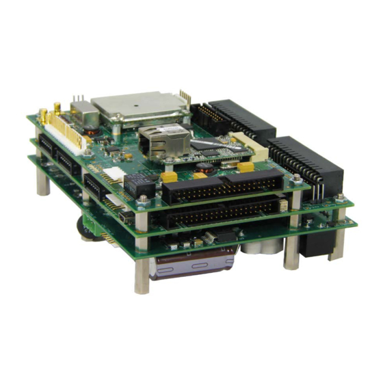
Chapter 2 Hardware 2.0 HARDWARE This chapter describes both the RC4000 boardset and common external devices that may be used for integrating an antenna system. 2.1 Boardset Devices This section describes the mechanical and electrical interfaces of the boards that comprise the RC4000 boardset. - Page 18 RC4000 ACU Boardset Chapter 2 Hardware The boardset may be laid out in other configurations in order to accommodate additional components or to minimize height. The following picture shows an alternative configuration. In this example the drive and computing boards are stacked together with the options board to the side.
- Page 19 Chapter 2 Hardware The following drawing shows the mounting hole spacing for the RC4000 boards. The Power/Drive board and the Computing/Interface board utilize all nine mounting holes. The Options board (on top in first picture) is narrower and only uses the six inner mounting holes.
- Page 20 RCI. In addition to board size, room for connectors, wiring harnesses, etc. should be considered. The following diagram shows how a boardset stack could fit inside a chassis with inside dimensions of 7.32" x 8.8191". NOTE: the RC4000 boardset may be purchased attached to the M-4KPLT1 plate.
-
Page 21: Electrical Interfaces
Hardware 2.1.2 Electrical Interfaces The interfaces available from each RC4000 board are detailed in this section. For context, typical uses of individual interfaces within an antenna system are described. Differences to these interfaces and how they are accommodated for a particular mount will be described in Appendix B - Mount Specific Data and in Appendix C - Enclosure Specific Data. -
Page 22: Power/Drive Board
The power/drive board’s main functions are to provide antenna motor control and distribute power to the rest of the RC4000 boardset. The board may be externally supplied with 24VDC input or convert AC input via optional (300 or 500 W) power supply modules. -
Page 23: J1 - Ac Power Input
RC4000 ACU Boardset Chapter 2 Hardware 2.1.2.1.1 J1 - AC Power Input Designation Pin Count Connector Type # "AC Power" Phoenix Terminal Header The Power/Drive board may be purchased with optional 300 or 500 Watt power supply cards. If a power supply card is present, AC input power is supplied to connector J1. -
Page 24: J2 - Dc Power
RC4000 ACU Boardset Chapter 2 Hardware 2.1.2.1.2 J2 - DC power Designation Pin Count Connector Type # "+24 Power" Molex Friction Lock Header The Power/Drive Board will be used to provide 24 VDC power to other cards in the boardset. Typically pins 1 &... -
Page 25: J5 - Motor Drive
" MOTOR/BRAKES" Drive Terminal Block The RC4000 drive section is designed to drive azimuth, elevation, and polarization motors up to 24 volt DC. The absolute maximum allowed motor current is 10 Amps. The motor drive module supports IR compensation, current limiting, dual speed operation, and dynamic braking. The drive train is also protected with resettable fuses. -
Page 26: J6 - Dc Power Input
RC4000 ACU Boardset Chapter 2 Hardware 2.1.2.1.6 J6 - DC Power Input Designation Pin Count Connector Type # Phoenix Terminal Header If an optional AC power supply is not present, DC input must be provided to connector J6, pins 1 & 2. If an AC power supply is present, leave pins 1 &... -
Page 27: Computing And Interface Board
RC4000 ACU Boardset Chapter 2 Hardware 2.1.2.2 Computing and Interface Board The Computing/Interface Board’s main functions are: 1) Run operational ACU software 2) Detect antenna sensor data via multiple interfaces 3) Control functions on the Drive and Options Boards The picture shows the top of the card. Spacers greater than 0.300" in length are required between the bottom of the card and the top of the power/drive board. -
Page 28: J1 - Interboard Bus B
RC4000 ACU Boardset Chapter 2 Hardware 2.1.2.2.1 J1 - Interboard Bus B Designation Pin Count Connector Type # "Bus B" Right Angle Shrouded Header The main function of Bus B is to provide drive control signals from the computing board to the drive board. -
Page 29: J2 - Red / Green Buttons
LOCATE & STOW functions (see 3.2.2.10 “VSAT mode”). NOTE: as with most RC4000 I/O pins, if these interfaces are not used for Red/Green button operation, the I/O pins could be re-tasked for some other custom functionality. -
Page 30: J3 - Receiver 1
RC4000 ACU Boardset Chapter 2 Hardware 2.1.2.2.3 J3 - Receiver 1 Designation Pin Count Connector Type # "Ext Rcvr" Phoenix Header The J3 connector is allocated to support various types of receivers. The flexible I/O includes: 1) +5 and +24 VDC for powering a receiver... -
Page 31: J4 - Serial Remote Control
NOTE: the remote control software option (3.1.5) must be present for this interface to be active. The most common way for this interface to be used is to implement the RC4000’s remote control protocol as described in that software option’s appendix. How the interface can be switched between the RS-232 and RS-422 standard will be described in that document. -
Page 32: J5 - Interboard 24 Vdc
USB mini-B The J6 USB mini-B female connector allows for factory and in-field programming of the RC4000's operational software via a standard USB cable. At power up, the RC4000's bootloader software checks the presence of a powered USB cable. If a USB cable is detected, the bootloader switches into downloading mode but if no USB is detected the bootloader will jump to the currently stored program for normal operation. -
Page 33: J7 - Interboard Bus A
RC4000 ACU Boardset Chapter 2 Hardware 2.1.2.2.7 J7 - Interboard Bus A Designation Pin Count Connector Type # "Bus A" Right Angle Shrouded Header The main function of Bus A is to provide control and communication signals between the computing and options boards. -
Page 34: J8 - Temperature Sensor
RC4000 ACU Boardset Chapter 2 Hardware 2.1.2.2.8 J8 - Temperature Sensor Designation Pin Count Connector Type # "Temp" Molex Friction Lock Header Pin 1 – 3.3 V pin 2 – V_Temp pin 3 – Gnd The Computing and Interface Board can optionally accommodate a temperature sensor interfaced into connector designator J8. -
Page 35: J10 - Keypad
RC4000 ACU Boardset Chapter 2 Hardware 2.1.2.2.10 J10 - Keypad Designation Pin Count Connector Type # "Keypad" Unshrouded Header The J10 connector allows a 4 row x 4 column keypad (see 2.2.6) to be utilized as part of the user interface. -
Page 36: J13A - Polarization Sensors
RC4000 ACU Boardset Chapter 2 Hardware 2.1.2.2.13 J13A - Polarization Sensors Designation Pin Count Connector Type # J13A "POL" Phoenix Double Header J13 provides a double row of pins. The top 16 pins are designated "J13A" and are typically allocated to supporting potentiometer, pulse and limit switch feedback from the polarization axis. -
Page 37: J13B - Acc/Compass
RC4000 ACU Boardset Chapter 2 Hardware 2.1.2.2.14 J13B – ACC/Compass Designation Pin Count Connector Type # J13B Phoenix Double Header J13 provides a double row of pins. The bottom 16 pins are designated "J13B" and are typically allocated for interfacing to various compass options. The flexible I/O scheme provides DC power, serial data and a 10 bit analog to digital input. -
Page 38: J14A - Azimuth Sensors
The azimuth stow switch must be closed when at the azimuth stow position. If the azimuth stow limit switch cable is severed, the RC4000 will think that the azimuth axis is not at the stowed position. Logic within the RC4000 will not allow elevation to move below the elevation down limit switch if an azimuth stowed condition is not recognized. -
Page 39: J14B - Elevation Sensors
If present, the elevation up switch must be open when the elevation axis has reached the up limit. If the elevation up limit switch cable is severed, the RC4000 will think that the elevation axis is at the up limit. -
Page 40: Resolver Card
Chapter 2 Hardware 2.1.2.3 Resolver Card The Resolver Board allows an RC4000-based ACU to be able to sense axis positions via resolvers by utilizing resolver-to-digital converters. Spacers supporting the Resolver Board need to be greater than or equal to 0.625" long. -
Page 41: J1 - Interboard 24 Vdc
All signal interfacing between the Resolver Board and the Computing and Interface Board are made via Bus A. Signal details for Bus A are provided in section 2.1.2.2.7. 2.1.2.3.3 J3 – Extra IO Designation Pin Count Connector Type # unmarked Molex Friction Lock Header This connector is not utilized for RC4000 applications. -
Page 42: J4 - Pol Resolver
RC4000 ACU Boardset Chapter 2 Hardware 2.1.2.3.4 J4 – Pol Resolver Designation Pin Count Connector Type # unmarked Phoenix Header J4 is dedicated to the polarization axis resolver. This part is typically not installed on the board unless the antenna includes a polarization resolver. -
Page 43: J5 - El Resolver
RC4000 ACU Boardset Chapter 2 Hardware 2.1.2.3.5 J5 – El Resolver Designation Pin Count Connector Type # unmarked Phoenix Header J5 is dedicated to the elevation axis resolver. 2.1.2.3.6 J6 – Az Resolver Designation Pin Count Connector Type # unmarked Phoenix Header J6 is dedicated to the azimuth axis resolver. -
Page 44: Options Board
Chapter 2 Hardware 2.1.2.4 Options Board The Options Board allows an RC4000-based ACU to be customized with the desired set of optional features such as GPS, DVB and Ethernet (IP). Spacers supporting the options board need to be greater than 0.437". -
Page 45: J1 - Interboard 24 Vdc
RC4000 ACU Boardset Chapter 2 Hardware 2.1.2.4.1 J1 - Interboard 24 VDC Designation Pin Count Connector Type # "Power" Molex Friction Lock Header J1 receives daisy chained 24 VDC from the computing board. Note that pins 1 & 2 could be used to daisy chain 24 VDC to additional places. -
Page 46: J3 - Compass/Inclinometer
2.1.2.4.3 J3 - Compass/Inclinometer Designation Pin Count Connector Type # Compass/Incl Molex Friction Lock Header This connector is used by the RC300 product but not utilized for RC4000 applications. -
Page 47: J4 - Relay
HPA DISABLE = DOWN_Limit OR Automated_Slewing_Motion OR TX_MUTE The contact arrangement is shown below: 2.1.2.4.5 J5 - Bar LEDs Designation Pin Count Connector Type # unmarked Molex Friction Lock Header This connector is used by the RC300 product but not utilized for RC4000 applications. -
Page 48: J6 - Interboard Bus A
All signal interfacing between the Options Board and the Computing and Interface Board are made via Bus A. Signal details for Bus A are provided in section 2.1.2.2.7. 2.1.2.4.7 J7 - LEDs Designation Pin Count Connector Type # Unmarked Unshrouded Header This connector is used by the RC300 product but not utilized for RC4000 applications. -
Page 49: J8 - Rf Input
L-Band power detector module. The L-Band power detector produces an output proportional to the broadband energy received. When this input is being used, it is indicated on RC4000 screens as the “RF” signal source. See sections 4.1.11.1... -
Page 50: J9 - Ethernet
Type # "Audio" Molex Friction Lock Header This connector is used by the RC300 product but not utilized for RC4000 applications. Note: This connector is included ONLY on Revision B options boards. It is not included in other revisions. 2.1.2.4.11 J11 - JTAG... -
Page 51: J14 - Ip Reset
RC4000 ACU Boardset Chapter 2 Hardware 2.1.2.4.14 J14 - IP Reset Designation Pin Count Connector Type # "IP RES" Molex Friction Lock Header If the IP (Ethernet) remote control option is present, these pins provide a way to manually reset the IP address. -
Page 52: J15 "Gps
RC4000 ACU Boardset Chapter 2 Hardware 2.1.2.4.16 J15 - GPS Designation Pin Count Connector Type # "GPS" Molex Friction Lock Header The J15 connector supports either 1) an internally mounted GPS receiver requiring a separate external antenna or 2) an external integrated GPS receiver/antenna. -
Page 53: J22 - Gps Pps
If the external GPS receiver is used, power/ground and serial data will be supplied from J15. The two most common external GPS units that have been supplied with the RC4000 are the Garmin 17xHVS and the Garmin 19xHVS. The model 17xHVS has been discontinued by Garmin and the 19xHVS is the recommended replacement. -
Page 54: J21 - Dvb-S2
Unmarked Tyco Vertical Header When the DVB-S2 option is included with the RC4000, the J21 connector provides the connections to the DVB-S2 carrier board, which is typically mounted directly above the options board on 7/8” tall standoffs. The DVB-S2 carrier board has a board-to-board connector that plugs directly into J21 so no external cables are required. -
Page 55: Connectors
Chapter 2 Hardware 2.1.2.5 Connectors This section provides details of the connectors used on the RC4000 boardstack. 2.1.2.5.1 Phoenix Terminal Header Phoenix Contact 1757255 Terminal Header; 12 A; 250 V; 5.08 mm; 3; Solder Mount; 1.4 mm; 4 kV; 320 V 2.1.2.5.2 Molex Friction Lock... -
Page 56: Usb
RC4000 ACU Boardset Chapter 2 Hardware 2.1.2.5.7 USB USB mini-B upstream receptacle 2.1.2.5.8 Tyco Vertical Header AMP 5103308-5 20 pin 5103308-1 10 pin 2.1.2.5.9 Unshrouded Header AMP 4-103321-8. 2.1.2.5.10 Phoenix Double Header Phoenix 1953855 2.1.2.5.11 SMB COAX connector, rf coaxial, smb straight pcb jack, 4 legs, mini 75 ohm 2.1.2.5.12 Ethernet... -
Page 57: External Equipment
See Appendix B for the correct orientation for a particular mount. The elevation position sense circuit of the RC4000 is designed to interface to the Lucas/Schaevitz AccuStar model 0211 1002-000 or 0211 1102-000 inclinometers. The inclinometer’s position reference is marked on the body of the inclinometer. - Page 58 RC4000 ACU Boardset Chapter 2 Hardware...
-
Page 59: External Gps Receiver
RC4000 ACU Boardset Chapter 2 Hardware 2.2.2 External GPS Receiver The optional GPS receiver (RC4000GPS) should be mounted in a position (such as the truck’s roof) where it has an unobstructed view of the horizon and sky. It should be mounted outside of the reflector when in a stowed position, with the connector (on the underside) towards the cable’s entry point into the... -
Page 60: Fluxgate Compass
“antenna mounted” value. The RC4000 uses the fluxgate to determine the true heading of the mount’s azimuth centerline (0.0 degrees azimuth). If the compass is not aligned in the direction of the azimuth centerline, that difference must be described in the azimuth offset configuration item (3.3.1.2.3). -
Page 61: Single Axis Compass
2.1.2.2.9. The standard LCD display has a temperature rating of 0⁰ to +50⁰C. There is an optional VFD (vacuum fluorescent display) that is rated for -40⁰ to +85⁰C. 2.2.6 4x4 Keypad The RC4000 can optionally be supplied with a 4 row by 4 column keypad. When used in conjunction with the 4x40 LCD (section 2.2.5), the keypad can be used for full user control of the antenna controller. -
Page 62: Local Jog Control Panel
RC4000 ACU Boardset Chapter 2 Hardware 2.2.7 Local Jog Control Panel The local jog control panel provides a simple keypad that includes the essential keys necessary for manual jog control and for automatic locate and stow routines. The jog panel is typically used when it is necessary to see the antenna as it is moving (if the remote control is not within eyesight) or when the remote control is not available. -
Page 63: Handheld Remote Front Panel
LCD and keypad connectors on the computing card. The HHRFP allows the keypad and display information to be communicated to/from the RC4000 via serial port (RS-422) or Ethernet port. There is an interface card within the HHRFP that handles the serial/Ethernet protocol, as well as driving the LCD and monitoring user key inputs. -
Page 65: Software
"front panel" interface (keypad and LCD) was present. 3.1.1 Modes The functionality of the RC4000 is achieved by placing the controller in the desired mode of operation. The figure shows the hierarchy of the RC4000’s modes. Each mode has a unique display screen that presents the information applicable to that mode’s operation. -
Page 66: Keypad Usage
Chapter 3 Software 3.1.2 Keypad Usage The keypad provides a flexible method of controlling the functionality of the RC4000. While each RC4000 mode has different requirements for user input, the use of the keypad remains consistent throughout all modes. The keypad provides for both specific actions and general data input. As an example, the UP_2_N key initiates an antenna up movement while in MANUAL mode but also allows for the entry of the number 2 when numeric entry is required or the indication of North when entering a latitude value. - Page 67 RC4000 ACU Boardset Chapter 3 Software KEY LABEL SPECIFIC FUNCTION GENERAL FUNCTION Momentary push switches between modes within group. Mode No specific function Button held for 3 seconds switches between operational and programming groups. Momentary push also exits sub-mode screens.
- Page 68 RC4000 ACU Boardset Chapter 3 Software KEY LABEL SPECIFIC FUNCTION GENERAL FUNCTION <1> Supplies “6” for numeric entry. Move azimuth axis clockwise in Az CW MANUAL mode Supplies West for longitude entry. (123°45W) <1> Supplies “7” for numeric entry. Requests move to predefined...
-
Page 69: Data Entry
Chapter 3 Software 3.1.3 Data Entry Many RC4000 screens request some type of user input. This section provides instructions on the entry of various types of data. Selection From List ( <0-9>SELECT ) When the user is prompted to select an action from a displayed list, pressing the numbered key corresponding to the desired action will initiate the action. -
Page 70: Display Layout
WAITING FOR NEXT PEAKUP <0>MENU MODE TITLE: in the upper right corner the title of the current RC4000 mode is displayed – in this example TRACK designates that the RC4000 is currently in track mode. NOTE: if the mode title is preceded by an exclamation point ( ! ), the mode was initiated by a remote command. -
Page 71: Software Initialization
RC4000 ACU Boardset Chapter 3 Software 3.1.5 Software Initialization Upon powering up the RC4000, an identification screen is displayed for five seconds. RC4000 MOBILE ANTENNA CONTROLLER (c) RESEARCH CONCEPTS INC. 2010 LENEXA, KANSAS USA (+1)913-422-0210 Please Wait ... RC4000 MOBILE ANTENNA CONTROLLER (c) RESEARCH CONCEPTS INC. - Page 72 Step & Memory Track supported Step & Memory plus Two Line Element set tracking supported Remote Control Options The RC4000 may provide optional support for controlling the mount from a remote (away from the front panel) location. CATEGORY DESIGNATOR DESCRIPTION...
- Page 73 RC4000 ACU Boardset Chapter 3 Software RECEIVER OPTIONS The RC4000 may provide optional support for controlling multiple integrated satellite receivers from two different connectors. The RC4000 can support the integrated DVB receiver along with two additional receivers. Receiver 1 Options The Receiver 1 option specifies support for both the RCI DVB receiver (integrated on the options board) along with an additional receiver via the REC1 connector.
- Page 74 Software MOUNT POSITION CONFIRMATION Following the power on screen, the RC4000 transitions to the appropriate screen based on whether or not a mount position (latitude/longitude/true heading) has been “saved”. If the mount’s position has been previously saved via the POSITION mode (3.2.2.7) or the STORE (3.2.2.4) mode, the following screen appears at power up requesting that the user confirm that this...
-
Page 75: Operating Group
(mag: or true:) to indicate that the heading value may be inaccurate due to compass error. If the RC4000's heading estimate has been "fixed", the field will be annunciated in capital letters (MAG: or TRUE:) to indicate confidence that the value represents an accurate magnetic or true heading. - Page 76 RC4000 ACU Boardset Chapter 3 Software The value of the predefined horizontal and vertical positions depends on what mode was active prior to entering the MANUAL mode. If a LOCATE operation occurred prior to MANUAL, the H and V values will be those automatically calculated by the LOCATE mode.
-
Page 77: Heading Fix
NOTE: to make this “fixed heading” persist through the next powering down of the RC4000, the mount’s position would need to be “saved” via the POSITION mode. If the difference is applied, the RC4000 will proceed to the POSITION screen. -
Page 78: Menu Mode
RC4000 ACU Boardset Chapter 3 Software 3.2.2 Menu Mode MENU mode allows the user to select one of listed modes. Pressing the Mode key will move to MANUAL mode. Note: RECALL and DELETE will not be displayed if no satellites are currently STOREd. -
Page 79: Deploy
The sequence of axis movement will be mount dependent. Following completion of movement to the deploy position, the RC4000 will return to MANUAL mode. The automatic movement may be terminated anytime by pressing the Stop key. -
Page 80: Stow
- the azimuth axis is moved to its predefined stow position (typically AZIM:0.0). After moving to this indicated position, the RC4000 will confirm the position by looking to see if the azimuth stow switch is active. If the azimuth stow switch is not recognized, the mount will be moved a short distance to either side of the current position trying to find the azimuth stow switch. -
Page 81: Locate
If it does, then investigate whether or not the GPS receiver’s view of the sky is blocked by buildings, etc. If a valid lat/lon is received from the GPS then the lat/lon information will be displayed. Next the RC4000 will flash “MAGVAR” while it calculates the local magnetic deviation as a function of latitude, longitude and time. -
Page 82: Satellite Selection
(3.3.1.2.3) or outside the up or down elevation limit (3.3.1.2.2), one these messages will be displayed to indicate that the RC4000 does not think it can move the antenna to the correct position to acquire the satellite. The user may have to move the vehicle to place it in an orientation that will allow the mount to move to the required position. - Page 83 LONGITUDE: described in decimal degrees (180.0W to 180.0E) INCLINATION: the number of degrees of orbital inclination. If a satellite is described as having an inclination greater than zero, the RC4000 will consider it an inclined orbit satellite and subsequently attempt to track its movement.
-
Page 84: Locate Automatic Movement
Note: this selection is not requested if the polarization configuration is defined as “circular” or if the polarization automove is disabled via the polarization configuration screen (3.3.1.2.4). In this case the RC4000 will only request that the user press the BKSP key to confirm that the automatic LOCATE movement is to proceed. -
Page 85: Azimuth Scanning Autopeak
3.2.2.3.3 Azimuth Scanning Autopeak The figure shows the movements made to perform an azimuth scanning (SCAN) operation. This SCAN operation enables the RC4000 to try to compensate for any azimuth inaccuracy caused by truck heading calculation errors. 1) as part of the basic LOCATE movement, the mount will be moved to the target elevation position and the polarization axis will be moved to the correct orientation. - Page 86 There might also be certain situations in which two satellites will be at a given elevation within that specified wider range, and the RC4000 will position the antenna at the point of the strongest signal, even though it is not the desired satellite. This value can be changed at any time.
-
Page 87: Spiral Search Autopeak
RC4000 ACU Boardset Chapter 3 Software 3.2.2.3.4 Spiral Search Autopeak The spiral search autopeak operation (SEARCH) performs somewhat differently from the SCAN operation. Whereas SCAN counts on the fact that a non-inclined orbit satellite should be at the calculated elevation, SEARCH must account for the fact that at a particular time an inclined orbit satellite may be above or below the nominal target elevation. -
Page 88: Terminal Peak Up
RC4000 ACU Boardset Chapter 3 Software 3.2.2.3.5 Terminal Peak Up NOTE: this option is only functional if the mount has been fitted with high resolution pulse or resolver sensors for both the azimuth and elevation axes. This option will not be available on some mounts where the ability to fit high resolution sensors is not available. -
Page 89: Store
3.2.2.7). If the position is saved, the user will be asked to verify the position upon power up of the RC4000. If the mount has moved, STOREd data will no longer be valid since the azimuth and elevation angles will no... -
Page 90: Recall
RC4000 ACU Boardset Chapter 3 Software 3.2.2.5 Recall NOTE: RECALL and DELETE modes will not be available from MENU if no satellites are currently “stored”. Satellites which have been stored in the controller's non-volatile memory (via STORE) can be recalled from the RECALL mode. -
Page 91: Position
The POSITION mode allows the user to set the latitude, longitude and heading of the vehicle for subsequent use in calculating pointing angles to satellites. The first screen that appears shows the current mount position used in the RC4000. Note: Mount “position” consists of the mount’s latitude, longitude and true heading of the azimuth centerline. -
Page 92: Heading
0.0 <1>MAG <2>TRU <3>COMPASS TRUE HDG: **** SELECT SOURCE <MODE>EXIT After the magnetic heading is entered, the RC4000 will apply the magnetic variation and azimuth offset to generate the true heading of the mount’s azimuth centerline. If the user wishes to manually enter true heading, press the 1 key and the prompt to enter heading will appear on line 3 as shown below. -
Page 93: Settings
Note: The SETTINGS mode may not be available on all software versions. The SETTINGS mode provides a way to change the operational characteristics of the RC4000 without requiring to go to the configuration group of screens. It also provides a way to reset a drive error without going to the DRIVE RESET maintenance screen. -
Page 94: Track
TRACK_SEARCH is entered when the satellite signal has been lost. The RC4000 utilizes Intelli-Search, an efficient search algorithm that minimizes errors associated with traditional box searches and frees the user from having to update vague search window parameters. -
Page 95: Vsat Mode
RC4000 must be taken out of VSAT mode. NOTE: VSAT “mode” refers to the overall functioning of the RC4000. VSAT is not a mode in the same sense as MANUAL, LOCATE, TRACK, etc. are modes. - Page 96 AZ: and EL: and the messages “READY TO LOCATE” and “PRESS ENTER” will be flashed. When ENTER is selected (or the antenna deployment has previously been confirmed), the RC4000 will automatically begin positioning the antenna to locate the satellite. The previously selected polarization orientation (Horizontal or Vertical) will be automatically calculated.
- Page 97 RC4000 front panel or a remote control interface. (Appendix PBO includes additional information regarding the RED/GREEN Button opteration.) IMPLEMENTATION In order for this simplified interface to be active, the RC4000 must be programmed and placed in VSAT mode as defined in section 3.2.2.10 (ENTERING VSAT MODE) of the baseline RC4000 user's manual.
- Page 98 RC4000 ACU Boardset Chapter 3 Software ACU MODE LIGHT INDICATION BUTTON ACTION POWER UP Both Red & Green lights flash No button action during power up MENU Both Red & Green lights on steady Green button initiates LOCATE mode (No errors) Red button initiates STOW mode LOCATE &...
- Page 99 RC4000 ACU Boardset Chapter 3 Software the green flashing codes vary, it is hoped that the user will recognize any green flashing light as an indication of normal operation (as long as there is not a red flashing code.) The following table provides descriptions of the flashing codes:...
-
Page 100: Programming Group
3.3.1 Configuration Mode The CONFIG mode allows users to view and/or modify various controller parameters and to enable or disable certain features. Many configuration items are used to customize the RC4000 to work with a particular installation. The CONFIG mode groups configuration items into screens containing between 1 to 10 individual items. - Page 101 RC4000 ACU Boardset Chapter 3 Software GROUP TITLE GROUP DESCRIPTION PARA. NORMAL ACCESS ITEMS EXPERT ACCESS PERMISSION SETS EXPERT ACCESS PERMISSION 3.3.1.1.1 LOCATION PRESETS LIST OF PRESET TRUCK LOCATIONS 3.3.1.1.2 SATELLITE PRESETS LIST OF PRESET SATELLITES 3.3.1.1.3 INSTALLATION ITEMS SYSTEM DEFINITON DEFINE SYSTEM OPTIONS 3.3.1.2.1...
-
Page 102: Normal Access Items
RC4000 ACU Boardset Chapter 3 Software NOTE: Software options (such as Inclined Orbit Tracking, Integrated DVB Receiver, etc.) may introduce additional configuration screens that will be described in the option's documentation. 3.3.1.1 NORMAL ACCESS ITEMS The three configuration groups contained in the “Normal” access allows the user to change items that would typically be required to be changed following system configuration. -
Page 103: Preset Locations
RC4000 ACU Boardset Chapter 3 Software 3.3.1.1.2 Preset Locations This group allows the user to customize a list of 20 commonly used mount locations. This list may be used for selecting mount lat/lon in the POSITION mode. LOC#: 1 CONFIG-LOCS NAME:RCI LAT:39°01N... -
Page 104: Preset Satellites
RC4000 ACU Boardset Chapter 3 Software 3.3.1.1.3 Preset Satellites This group allows the user to customize a list of 20 commonly used satellites. The LOCATE mode allows the user to select a satellite (3.2.2.3.1) from this “preset” list. SAT#: 1... - Page 105 5) N – Neutral linear polarization (typically halfway between Horizontal and Vertical) NOTE: the preset list only contains data about a satellite. With respect to the RC4000 there is sometimes confusion between the preset list and the list of STOREd satellite data (3.2.2.4).
-
Page 106: Installation Access Items
If specified as not present (0), the “NO GPS PRESENT” message will be displayed in various RC4000 screens. If the GPS option was not purchased, this field will always remain at 0. If the GPS is specified as “TOP” or “BACK” (referring to an antenna mounted GPS), the RC4000 will require that the dish be moved to the DEPLOY position to obtain GPS location information. - Page 107 If the compass is specified as “TOP” or “BACK” (referring to an antenna mounted compass), the RC4000 will require that the dish be moved to the DEPLOY position to obtain magnetic heading information. If the compass option was not purchased, this field will always remain at 0.
-
Page 108: Elevation Calibration
COUNT DIRECTION <0-NORMAL 1-REVERSED> The elev_pulse_count_reversed_item defines whether the polarity of the Elevation resolver matches that of the RC4000 resolver circuitry. If the raw Elevation resolver angle decreases as the mount moves UP, the DIR item must be described as reversed. -
Page 109: Azimuth Calibration
These positions are used to trigger the display of the Reposition Truck message. When the RC4000 calculates an antenna pointing solution in LOCATE mode, it checks these values to see if the dish can be physically moved to that position. Thus the Reposition Truck message is displayed when the antenna is incapable of moving to the azimuth position required to intercept the desired satellite. -
Page 110: Polarization Calibration
RC4000 ACU Boardset Chapter 3 Software 3.3.1.2.4 Polarization Calibration VREF:2.50 OFF: CONFIG-POL CCW: -90.0 90.0 SF: 48.45 REF:0 ZERO DEG VOLTAGE <1.00–4.00 VOLTS> VREF: ZERO DEG VOLTAGE <1.00-4.00 VOLTS> The pol_reference_voltage defines the voltage present when the polarization axis is in its center of motion. - Page 111 RC4000 ACU Boardset Chapter 3 Software OPTIONAL MULTI-FEED OPERATION When multiple, swappable feeds exist in a system, the multi-feed capability allows the ACU to detect and configure itself according to the currently attached feed. The multi-feed (“pol-id”) scheme allows for unique properties, polarization movement, position indication, and even locate signal source.
- Page 112 RC4000 ACU Boardset Chapter 3 Software The feed index, C|B|A bit pattern, and default feed identifier are shown in the following table: FEED # Bit C Bit B Bit A Default Sensed Feed Default Feed Identifier C-Band Linear “C-LP” X-Band Linear “X-LP”...
-
Page 113: Feed Definition
RC4000 ACU Boardset Chapter 3 Software 3.3.1.2.5 Feed Definition CONFIG-FEED TYPE:1 LO:10750 BAND:1 <0>CIRCULAR <1>SINGLE <2>DUAL TYPE: <0>CIRCULAR <1>SINGLE <2>DUAL The polarization_type configuration item specifies the configuration of the feed drive. This item will be used by the controller to determine the appropriate automatic movement of the polarization axis. - Page 114 RC4000 ACU Boardset Chapter 3 Software OPTIONAL MULTI-FEED OPERATION Refer to section 3.3.1.2.4 Polarization Calibration. This following description is related to systems which implement a multi-feed scheme. POL#:0 CONFIG-FEED TYPE:1 LO:10750 BAND:1 ID:KULP <SCR> THRU LIST, <ENTER> TO MODIFY DATA...
-
Page 115: Autopeak
/SS2/RF SIGNAL FACTORS screens. If the first scan is unsuccessful, then the RC4000 will attempt a second scan that doubles the scan range. If the second scan in unsuccessful, then the RC4000 will attempt a third scan that will move limit to limit in the Azimuth axis. - Page 116 RC4000 ACU Boardset Chapter 3 Software OPTIONAL MULTI-FEED OPERATION Refer to section 3.3.1.2.4 Polarization Calibration. This following description is related to systems which implement a multi-feed scheme. POL#:0 CONFIG-AUTOPEAK LOCATE SOURCE:8 SCAN:2 TARGET PEAK:2 POL AUTOMOVE:1 TILT:2 <SCR> THRU LIST, <ENTER> TO MODIFY DATA...
-
Page 117: Ss1 Signal Strength Factors
TIME: LOCK TIME <0.0-10.0> SECONDS This item defines how long the RC4000 will wait after each step before sampling signal strength. Increasing this value may be required to allow equipment such as a modem to generate an AGC output. THRES: SCAN SLOW THRESHOLD <0-1000>... -
Page 118: Ss2 Signal Strength Factors
TIME: LOCK TIME <0.0-10.0> SECONDS This item defines how long the RC4000 will wait after each step before sampling signal strength. Increasing this value may be required to allow equipment such as a modem to generate an AGC output. THRES: SCAN SLOW THRESHOLD <0-1000>... -
Page 119: Rf Signal Strength Factors
RC4000 ACU Boardset Chapter 3 Software 3.3.1.2.9 RF Signal Strength Factors This screen defines how the L-Band power detector (RF) input is used. See section 2.1.2.4.8 references to the use of signal strength inputs and section 4.1.11 for information regarding calibration. -
Page 120: Super-User Access Items
RC4000 ACU Boardset Chapter 3 Software 3.3.1.3 Super-User Access Items This set of configuration groups allows the user to modify parameters that are not typically changed for a particular installation. Usually these items address parameters that have been previously characterized for a particular mount. -
Page 121: Azimuth Angle Movement
RC4000 ACU Boardset Chapter 3 Software 3.3.1.3.2 Azimuth Angle Movement The CONFIG-AZ ANG screen contains configuration items for calibrating large automatic azimuth movements based on angle (potentiometer or resolver-based) position feedback. See the Drive System theory section 4.3.3. CONFIG-AZ ANG FAST/SLOW: 2.5... -
Page 122: Azimuth Count Movement
RC4000 ACU Boardset Chapter 3 Software 3.3.1.3.3 Azimuth Count Movement The CONFIG-AZ PULSE screen contains items for configuring automatic movements based on sensor count (resolver or pulse) azimuth position feedback. CONFIG_AZ COUNT FAST/SLOW: 50 COAST: MAX ERROR: 2 TRIES: 3 FAST/SLOW THRESHOLD <0 –... -
Page 123: Azimuth Drive Parameters
CURRENT LIMIT <0-10 AMPSx10, 0=OFF > The RC4000 motor drive can supply up to 10 Amps. The current limit setting is a value between 0 to 100 and the unit of measure is tenths of an Amp. For example, if the desired current limit for the Azimuth axis is 7.5 Amps, then enter a value of 75 (7.5 x 10 = 75.) Or the desired current limit is 10 Amps, then enter a... - Page 124 RC4000 ACU Boardset Chapter 3 Software RUN: RUNAWAY SLOP <0.0-10.0 DEG, 0.0=OFF> The azim_runaway_slop_item specifies the amount of movement that may be sensed before a runaway condition is declared when the antenna is not supposed to be moving. The unit of measure of the entered value is in hundredths of a degree (0.01 deg). If the installation has pulse-based sensing this value will indicate the number of pulses the system may see before declaring a runaway.
-
Page 125: Elevation Angle Movement
RC4000 ACU Boardset Chapter 3 Software 3.3.1.3.5 Elevation Angle Movement The CONFIG-EL ANG screen contains configuration items for calibrating large automatic elevation movements based on angle (inclinometer or resolver-based) position feedback. See the Drive System theory section 4.3.3. CONFIG-EL ANG FAST/SLOW: 2.5... -
Page 126: Elevation Count Movement
RC4000 ACU Boardset Chapter 3 Software 3.3.1.3.6 Elevation Count Movement CONFIG_EL COUNT FAST/SLOW: 50 COAST: MAX ERROR: 2 TRIES: 3 FAST/SLOW THRESHOLD <0 – 999 PULSES> FST/SLW: FAST/SLOW THRESHOLD <0 - 999 PULSES> During an automatic move, the elev_fast_slow_pulse_threshold configuration item is used to set the number of pulses before a target position is reached when the controller switches the speed of the drive from fast to slow. -
Page 127: Elevation Drive Parameters
CURRENT LIMIT <0-10 AMPSx10, 0=OFF > The RC4000 motor drive can supply up to 10 Amps. The current limit setting is a value between 0 to 100 and the unit of measure is tenths of an Amp. For example, if the desired current limit for the Elevation axis is 7.5 Amps, then enter a value of 75 (7.5 x 10 = 75.) Or the desired current limit is 10 Amps, then... - Page 128 RC4000 ACU Boardset Chapter 3 Software RUN: RUNAWAY SLOP <0.0-10.0 DEG, 0.0=OFF> The elev_runaway_slop_item specifies the amount of movement that may be sensed before a runaway condition is declared when the antenna is not supposed to be moving. The unit of measure of the entered value is in hundredths of a degree (0.01 deg). If the installation has pulse-based sensing this value will indicate the number of pulses the system may see before declaring a runaway.
-
Page 129: Polarization Angle Movement
RC4000 ACU Boardset Chapter 3 Software 3.3.1.3.8 Polarization Angle Movement The CONFIG-POL ANG screen contains configuration items for calibrating polarization movements based on potentiometer position feedback. See the Drive System theory section 4.3.3. CONFIG-POL ANG FAST/SLOW: 1.0 COAST:0.1 MAX ERROR:0.10 TRIES: 3 FAST/SLOW THRESHOLD <0.0-10.0 DEGREES) - Page 130 RC4000 ACU Boardset Chapter 3 Software OPTIONAL MULTI-FEED OPERATION Refer to section 3.3.1.2.4 Polarization Calibration. This following description is related to systems which implement a multi-feed scheme. POL#:0 CONFIG-POL ANG FAST/SLOW: 1.0 COAST:0.1 MAX ERROR:0.10 TRIES: 3 <SCR> THRU LIST, <ENTER> TO MODIFY DATA...
-
Page 131: Pol Drive Parameters
CURRENT LIMIT <0-10 AMPSx10, 0=OFF > The RC4000 motor drive can supply up to 10 Amps. The current limit setting is a value between 0 to 100 and the unit of measure is tenths of an Amp. For example, if the desired current limit for the Polarization axis is 7.5 Amps, then enter a value of 75 (7.5 x 10 = 75.) Or the desired current limit is 10 Amps, then... - Page 132 RC4000 ACU Boardset Chapter 3 Software RUN: RUNAWAY SLOP <0.0-10.0 DEG, 0.0=OFF> The pol_runaway_slop_item specifies the amount of movement that may be sensed before a runaway condition is declared when the antenna is not supposed to be moving. The unit of measure of the entered value is in hundredths of a degree (0.01 deg). If the installation has pulse-based sensing this value will indicate the number of pulses the system may see before declaring a runaway.
- Page 133 RC4000 ACU Boardset Chapter 3 Software OPTIONAL MULTI-FEED OPERATION Refer to section 3.3.1.2.4 Polarization Calibration. This following description is related to systems which implement a multi-feed scheme. POL#:0 FST:100 ACC:100 CONFIG-POL DRV SLW: 50 DEC:100 JAM: 0.2 FDB: 250 CL: 20 5 RUN: 2.0 SDB: 100...
-
Page 134: Stow & Deploy Positions
RC4000 ACU Boardset Chapter 3 Software 3.3.1.3.10 Stow & Deploy Positions The STOW & DEPLOY group allows the user to change the target positions for STOW and DEPLOY movements. AZ_STW: 0.0 AZ_DEP: CONFIG-STOW EL_STW: -67.5 EL_DEP: 17.3 SNUG: 0.0 PL_STW: 0.0 PL_DEP:... - Page 135 RC4000 ACU Boardset Chapter 3 Software STOW & DEPLOY WITH OPTIONAL MULTI-FEED OPERATION Refer to section 3.3.1.2.4 Polarization Calibration. This following description is related to systems which implement a multi-feed scheme. When a multi-feed scheme is in use, the STOW & DEPLOY screen is split into two separate CONFIG mode screens.
- Page 136 RC4000 ACU Boardset Chapter 3 Software POL STOW & DEPLOY The POL STOW & DEPLOY group allows the user to change the target positions for STOW and DEPLOY movements for the polarization axis. POL#:0 CONFIG-STOW PL_STW: 0.0 PL_DEP: PL_MOVE:3 <SCR> THRU LIST, <ENTER> TO MODIFY DATA PL_STW: POL STOW <-180.0/180.0>...
-
Page 137: Shake
RC4000 ACU Boardset Chapter 3 Software 3.3.1.3.11 SHAKE AZ 1: -40.0 2: 50.0 3: 0.0 CONF-SHAKE EL 1: 30.0 2: 40.0 3: -67.5 CYCLE: 100 PL 1: -10.0 2: 10.0 3: 0.0 DELAY: MOVE 1 AZIM <-180.0/180.0> AZ #: MOVE # AZIM <-180.0/180.0>... -
Page 138: Maintenance Items
RC4000 ACU Boardset Chapter 3 Software 3.3.2 Maintenance Items 1-VOLTS 2-DRIVE 3-TIME MAINT 5-LIMITS 6-GPS COM 7-CMP COM 8-MOVETO 9-FG CAL 0-SHAKE .-SYS INFO This screen provides a menu system for selecting the various maintenance screens described in the following paragraphs. Pressing the Mode key from this screen will return the controller to the CONFIG- MENU screen. -
Page 139: Analog To Digital Voltage
RC4000 ACU Boardset Chapter 3 Software 3.3.2.1 Analog to Digital Voltage The AD VOLTAGES maintenance screen shows the current voltage levels sensed at the microcontroller’s analog to digital inputs. There are too many input channels to show all voltages on one screen, so the user is prompted to choose either 10 bit or 12 bit resolution voltages. -
Page 140: Bit Adc Voltages
Note that all of the analog to digital channels have some associated scaling and conditioning circuitry in the RC4000. Therefore the voltages seen at this screen may not be exactly the same as the input voltages external to the RC4000. -
Page 141: Drive Error Resets
OFFSET: 1-DATE 2-TIME 3-SYNCH 4-ZONE 5-OFFSET SYSTEM:DD/MM/YY HH:MM:SS Current date and time as maintained by the RC4000’s real-time clock. DISPLAY: Current “reference” time that will be displayed in several screens (MANUAL, MENU). This time is offset from the system time by the OFFSET number of hours described later. -
Page 142: Tbd Maintenance
RC4000 ACU Boardset Chapter 3 Software The values for the time parameters may be altered by the actions described next: 1-DATE ENTER DATE DD.MM.YY This action allows the user to manually set the date. The prompt indicates that the / delimiter for date is entered by using the (decimal point) key. -
Page 143: Limits Maintenance
<MODE>EXIT The limits maintenance screen shows the current state of each limit switch as sensed by the RC4000’s microcontroller. The state of each limit is shown as 0 if off or 1 if on. An * is displayed if the particular limit switch is not relevant for the particular mount (there is no POL STOW switch in the above example). -
Page 144: Gps Serial Port Diagnostics
RC4000 ACU Boardset Chapter 3 Software 3.3.2.6 GPS Serial Port Diagnostics This screen allows the user to ascertain if the GPS receiver is communicating correctly with the RC4000. <BKSP> TO FREEZE DISPLAY GPS COMM $GPRMC,133544,V,3856.0856,N,09444.8377, W,000.0,000.0,080499,003.6,E*7B≡≡$GPGGA, 190449,3856.0856,N,09444.8377,W,0,00,,,M The screen shows the raw ASCII data coming from the GPS receiver. If there is correct communication established with the GPS, somewhere in the lines of displayed characters the strings “GPRMC”... -
Page 145: Moveto
RC4000 ACU Boardset Chapter 3 Software 3.3.2.8 MOVETO The MOVETO mode is intended to provide an easy way to move the antenna to a certain position for doing testing such as cutting antenna patterns. This mode is also useful for tuning up automatic movements. -
Page 146: Fluxgate Calibration Procedure
(0-9,>5 PREFFERRED) CALIBRATION FINISHED, <MODE> TO EXIT COMM ERROR At any time during the calibration procedures, if the RC4000 detects an abnormal response from the fluxgate, the communication error message is displayed. Exit the procedure by pressing the Mode key. -
Page 147: Shake
RC4000 ACU Boardset Chapter 3 Software 3.3.2.10 Shake The SHAKE mode performs repetitive mount movements. The SHAKE mode is for support of mount testing and for automatic mount demonstrations such as trade shows. The SHAKE mode is only available if expert access is enabled. -
Page 148: System Information
RC4000 ACU Boardset Chapter 3 Software 3.3.2.11 System Information Selecting the Stop/. key from the MAINTENANCE screen triggers a display of various system/software information. Serial Number: 0 SYSTEM INFO Firmware: RC4K-TEST-GTRSB Version: 0.07 BN: EG0926 <MODE>EXIT... -
Page 149: Support
Initial Configuration may be done in any area (possibly a shop environment) where the antenna may be moved throughout its entire range of travel. At this point, the installer will have to start operating the RC4000 from the front panel. Section 3 will need to be reviewed to perform the steps described below. -
Page 150: Software Initialization
GPS receiver is present, if and how the fluxgate compass is mounted, the size of the reflector in use and what mode the user prefers the RC4000 to go to upon power up. MODE:2... - Page 151 RC4000 ACU Boardset Chapter 4 Support One of the MAINTENANCE screens used is the Analog to Digital Voltage screen (see 3.3.2.1). This screen shows raw data coming from antenna position sensors (potentiometers and resolvers). AZ: 2.5000 2048 12 BIT ADC EL: 0.0012...
-
Page 152: Elevation Calibration
ELEV STOW and Down (DN) limits are active. Also confirm that the elevation UP limit is inactive. If the UP limit is active, the RC4000 will be prevented from moving the elevation axis up from the stowed position. - Page 153 Move to the Elevation Calibration configuration screen and enter the recorded value in the REF_V item. This will define to the RC4000’s software the voltage that should be seen when the elevation axis is in its reference position. To verify that data has been entered correctly, return to the MANUAL mode screen.
- Page 154 This step is performed to characterize the output signal from the elevation inclinometer. 1) With the elevation axis in the reference position, note the angle (using an accurate inclinometer placed on the mount itself, not the angle displayed on the RC4000) and the A/D voltage at that point.
- Page 155 NOTE: an alternate method for calculating the output signal from the inclinometer is to use the data supplied by the inclinometer manufacturer for each individual inclinometer and multiply by the gain (0.823) in the RC4000’s circuitry. (example: 59.27 mV/deg * 0.823 = 48.78 ) STEP 5. Up Limit Confirmation Move the elevation axis to the UP physical limit and confirm that the “UP”...
-
Page 156: Azimuth Calibration
Move to the Azimuth Calibration screen and enter the recorded value in the REF_V item. This will define to the RC4000’s software the voltage that should be seen when the azimuth axis is in its centerline position. To verify that data has been entered correctly, return to the MANUAL mode screen. The displayed azimuth angle should be 0.0 +/- 0.1 degrees. - Page 157 The next step is to move the azimuth axis to confirm drive and sensor polarity. Azimuth clockwise and counterclockwise is defined as seen by an observer located above the antenna looking down on the antenna. In MANUAL mode, when the AZ CW (6) key of the RC4000 is depressed the antenna motors must be wired (section 2.1.2.2.15) so that the antenna moves clockwise.
- Page 158 RC4000 ACU Boardset Chapter 4 Support STEP 6. Azimuth Software Limits. The CCW and CW configuration item values found in the AZIMUTH CALIBRATION screen should be set to reflect the physical limits of azimuth travel. Note that these limits don’t physically limit azimuth travel but are used by software to determine if a calculated pointing solution is outside of the mount’s range of...
-
Page 159: Polarization Calibration
RC4000 ACU Boardset Chapter 4 Support 4.1.4 Polarization Calibration The following steps will require values to be entered in the POLARIZATION CALIBRATION configuration screen (see 3.3.1.2.4). REF_V:2.50 OFF: CONFIG-POL CCW: 90.0 CW: 90.0 SF:41.67 TYPE:2 REF:1 H: -45.0 V: 45.0 AUTO: 1 SET REFERENCE VOLTAGE <2.00 –... - Page 160 RC4000 ACU Boardset Chapter 4 Support The following diagram shows a typical situation of two waveguides that rotate together. Note that the diagram should be considered as if the observer is behind the reflector looking towards the arc of satellites. This representation is relevant for both prime focus and dual reflector antennas.
- Page 161 Polarizaiton Electrical Limits. Other mounts may not have polarization limit switches. In this case, the RC4000 allows for the CW and CCW limits to be set based on the polarization potentiometer voltage. The position of these limits is defined in the MAINTENANCE – POL CALIBRATION screen (3.3.1.2.4) under the CW and CCW entries.
-
Page 162: Fast/Slow Motor Speed
RC4000 ACU Boardset Chapter 4 Support 4.1.5 Fast/Slow Motor Speed The fast and slow output voltages for your particular mount will be set at the factory and typically will not need to be adjusted. The FAST and SLOW speed parameters can be adjusted in the AZIMUTH/ELEVATION/POLARIZATION DRIVE PARAMETERS Config Menu screens (3.3.1.3.4,... -
Page 163: Compass Calibration
RC4000 ACU Boardset Chapter 4 Support 4.1.9 Compass Calibration Ferrous metal on the vehicle distorts the earth's magnetic field in the vicinity of the vehicle. The flux gate indicates the direction of the distorted magnetic field. The flux gate calibration procedure provides a method to correct for this distortion (caused by the vehicle/platform) of the earth's magnetic field and obtain the vehicle's actual magnetic heading. -
Page 164: Azimuth And Elevation Alignment
RC4000 ACU Boardset Chapter 4 Support 4.1.10 Azimuth and Elevation Alignment This step attempts to discover and compensate for offsets in azimuth and elevation position sensing. Offsets may be introduced due to several factors including mechanical tolerances and slight inaccuracies in installation. - Page 165 RC4000 ACU Boardset Chapter 4 Support Elevation Alignment It is fairly easy to observe errors in the elevation calibration. If test data shows that the actual elevation angle that a satellite is found is consistently above or below the calculated target, then it can be concluded that an elevation offset should be applied. Enter the appropriate value in the OFF field of the elevation calibration screen (3.3.1.2.2).
-
Page 166: Signal Strength Adjustment
RC4000 ACU Boardset Chapter 4 Support 4.1.11 Signal Strength Adjustment The RC4000 can sense satellite signal strength via the L-band power detector (2.1.2.4.8) or the signal strength input circuits (2.1.2.2.3 or 2.1.2.4.2). This section describes how to configure the signal strength input circuits for use with the satellite receivers used for a particular installation. -
Page 167: Amplifier Gain Vs. Frequency Characterization
RC4000 ACU Boardset Chapter 4 Support 4.1.11.4 Amplifier Gain vs. Frequency Characterization An amplifier's gain vs. frequency characteristic, or gain flatness, is the variation of the amplifier's gain with changing frequency. The ideal response is to have a flat gain characteristic (the gain does not vary with frequency). -
Page 168: Pulse Scale Factors
It is critical that these numbers are accurate since the tracking algorithms use them to determine step sizes (in pulse counts). Note that the RC4000 counts both rising and falling edges of the position pulses so that a single position pulse generates 2 position counts. - Page 169 SCALE FACTOR FOR RESOLVER SYSTEMS The RC4000 uses the actual digitized resolver count in the same way it uses a pulse count. The RC4000 utilizes a 16 bit resolver to digital converter which generates a count value from 0 to 65,535. Typically the resolver sensor rotates with the antenna.
-
Page 170: Operational Presets
(3.3.2.3.) 4.1.15 Mechanizing Automatic Locates Performing all of the previous installation steps correctly should place the RC4000 into a state where automatic locating of satellites may be accomplished. This section discusses the typical final actions necessary to mechanize an automatic locate. The LOCATE mode is described in section 3.2.2.3. - Page 171 RC4000 ACU Boardset Chapter 4 Support ensure that a signal lock indication is generated by the modem before the autopeak scan operation steps past the satellite of interest. In the AUTOPEAK configuration screen (3.3.1.2.6), enable the autopeak function using RF, LOCATE...
-
Page 172: Troubleshooting
Failure of a limit switch to activate properly may be due to the limit switch mechanism itself, cabling to the limit switch or failure of the RC4000 to sense the limit switch correctly. Isolating the problem to the RC4000 or switch/wiring may be accomplished by placing wire jumpers across appropriate pins on the J13A connector (2.1.2.2.13), the J14A connector (2.1.2.2.15) and the J14B connector (2.1.2.2.16). -
Page 173: Motor Drive
MANUAL mode. There are several things to note: When a jog key is pushed, can relays inside the RC4000 be heard activating? If no relays are heard, a limit switch condition may be present that disallows movement in the axis in question. Review the above limit switch discussion. -
Page 174: Automatic Movements
When a manual jog key is released, the axis continues moving for about 5 seconds. This condition is indicative of a drive relay failure inside the RC4000. The RC4000 has a “safety” relay in series with the normal drive relays that opens 5 seconds after any commanded movement is stopped. -
Page 175: Fluxgate Compass
NO COMPASS. This message indicates that the compass_present item in the System Definition (3.3.1.2.1) configuration item has been set to 0 indicating that no compass is attached to the RC4000. No attempt will be made to parse compass data in this state. If a compass is truly attached, set the compass_present item to 1 or 2. -
Page 176: Alarm Displays
4.2.6.1 FLASH / NVRAM VERSION MISMATCH If the RC4000 recognizes a mismatch in the stored data (antenna mount type data) then this error code will appear. The only time this error typically would occur is during a software change in the ACU. A system reset to defaults may clear this error (3.3.1.3.1). -
Page 177: Drive Overtemp
4.2.6.11 REPLACE HAND CRANKS If the antenna has hand cranks that have sensed feedback to the RC4000, this error code will display if the hand cranks are not in a position that allows safe antenna movement via the ACU. -
Page 178: Acu Topics
Given the mount’s latitude and longitude and the pointing vector to the satellite, the RC4000 calculates the elevation (with respect to local horizontal) required. Feedback from the inclinometer on the elevation... - Page 179 An azimuth movement of 90 (135 – 45) degrees clockwise is therefore needed to point at the satellite. Since a position sensor on the azimuth axis is always active, the RC4000's default displayed azimuth value is that of the antenna angle. Derived estimates of the magnetic and true heading of the mount may...
-
Page 180: Timekeeping
System time is maintained by the RC4000’s real time clock. The real-time clock is backed up by battery so that system time is available as soon as the RC4000 powers up. The system time is used to calculate sidereal time for maintaining track tables. Since satellite’s do not experience time shifts (such as from Standard Time to Daylight Savings Time or when moving from one time zone to another), it is recommended that system time not be modified while active track tables are present. - Page 181 Anti-Reversal In order to save wear on the drive motors, the RC4000 limits how fast an axis may reverse its direction. This mechanism prevents a motor from instantly changing direction before coasting to a stop in the original direction.
-
Page 182: Polarization Control
The Fast/Slow Transition parameter defines how far away from a target position the RC4000 will switch from fast to slow motor speed. The Coast Range defines where the RC4000 will de-energize the motor drive to allow the mount’s inertia to coast into the target position. The Max Error parameter defines how close to the target position will be considered good enough. -
Page 183: Magnetic Variation
In order to calculate satellite pointing solutions, the mount’s orientation with respect to True North must be known. The RC4000 uses a compass to measure the local horizontal component of the earth’s magnetic field. The earth’s magnetic field is very irregular as shown in the following map. -
Page 184: System Performance
3.2.2.3. The RC4000 uses a 12-bit analog to digital converter for measuring voltages from azimuth, elevation and polarization potentiometers as well as measuring signal strength inputs. In most cases this provides adequate resolution but should be considered. For example, if the azimuth axis has 360 degrees of travel, the resolution achieved is 360/4096 = ~0.088 degrees. - Page 185 RC4000 ACU Boardset Appendix A Expert Access Codes APPENDIX A - EXPERT ACCESS CODES To initiate INSTALL ACCESS permission or to RESET SYSTEM DEFAULTS, the user must enter the five digit code: 42458 To initiate SUPER-USER ACCESS permission, the user must enter the five digit code:...
Need help?
Do you have a question about the RC4000 and is the answer not in the manual?
Questions and answers