Table of Contents
Advertisement
Quick Links
Advertisement
Table of Contents

Related Manuals for RESEARCH CONCEPTS RC3000


Summary of Contents for RESEARCH CONCEPTS RC3000
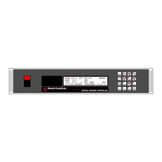
- Page 1 RC3000 MOBILE ANTENNA CONTROLLER USER’S MANUAL Contents subject to change 1 December 2005 RESEARCH CONCEPTS INC. 5420 Martindale Road Shawnee, Kansas 66218-9680 USA VOICE: (913) 422-0210 FAX: (913) 422-0211 www.researchconcepts.com support@researchconcepts.com Serial No________...
-
Page 3: Revision History
REVISION HISTORY DATE MODIFICATION SOFTWARE VERSION 8 March 1999 Preliminary document 1.00 13 April 1999 Initial Release 1.04 1 June 1999 Update 1.07 13 March 2000 Software Update 1.16 15 November 2002 Chapter 2 Update 1.37 10 January 2003 Appendix E Update 1.38 3 January 2005 Manual Format Update... -
Page 4: Warranty Information
WARRANTY INFORMATION Research Concepts, Inc.(RCI) warrants to the original purchaser, this product shall be free from defects in material and workmanship for one year, unless expressed otherwise, from the date of the original purchase. During the warranty period, RCI will provide, free of charge, both parts and labor necessary to correct such defects. -
Page 5: Table Of Contents
1.3.9 System Performance...........................15 1.4 S ..............................16 PECIFICATIONS 2.0 INSTALLATION ..............................17 2.1 E .............................18 QUIPMENT OUNTING 2.1.1 RC3000 Antenna Controller........................18 2.1.2 GPS Receiver..............................19 2.1.3 Fluxgate Compass ............................20 2.1.4 Electronic Clinometer ..........................22 2.2 E ..........................24 LECTRICAL ONNECTIONS 2.2.1 Power Entry..............................25 2.2.2 Motor Drive..............................26 2.2.3 Drive Sense..............................27... - Page 6 3.0 DETAILED OPERATION ..........................63 3.1 O ............................63 PERATION VERVIEW 3.1.1 Modes................................. 63 3.1.2 Keypad Usage ............................64 3.1.3 Data Entry ..............................66 3.1.4 Display Layout............................67 3.2 O ............................68 PERATING ROUP 3.2.1 Manual Mode............................. 69 3.2.1.1 Heading Fix ................................71 3.2.1.2 Waveguide Switch..............................
- Page 7 APPENDIX A - EXPERT ACCESS / RESET DEFAULTS CODE APPENDIX B - MOUNT SPECIFIC DATA APPENDIX C - DC MOTOR CONTROLLER The following appendices describe optional features of the RC3000. These appendices will be included in the manual if the option is present. APPENDIX REM - REMOTE CONTROL...
-
Page 9: Introduction
The RC3000 then uses the data from the sensors to accurately steer the antenna to the calculated azimuth and elevation angles. The RC3000 also optionally automates the function of tracking inclined orbit satellites. -
Page 10: Manual Conventions
Latitude and longitude of the mount are presented in degree/minute (38°56 N) format. When referring to a particular RC3000 mode of operation, that mode’s name will be capitalized – ex. LOCATE. Throughout the RC3000 manual and software, the latitude, longitude and true heading of the mount are collectively referred to as the mount’s “position”. -
Page 11: Rc3000 Features
Chapter 1 Introduction 1.2 RC3000 Features The RC3000 antenna controller is designed to automate the operation of mobile (both vehicle mounted and deployable) mounts. Features provided include: - Automatic azimuth and elevation pointing solution calculation - Optional GPS receiver for determination of antenna latitude and longitude... - Page 12 Step & Memory Track supported Step & Memory plus Two Line Element set tracking supported Remote Control Options The RC3000 may provide optional support for controlling the mount from a remote (away from the front panel) location. CATEGORY DESIGNATOR DESCRIPTION...
-
Page 13: Theory Of Operation
RC3000 and for entering data. KEYPAD. The 4 row by 4 column keypad allows the user to enter data and commands to the RC3000. DIGITAL BOARD. The digital board is essentially a small computer containing a microcontroller, memory, real-time clock and circuitry to monitor and drive the keypad and LCD. -
Page 14: System Interface Requirements
- IR compensation to improve load regulation POWER ENTRY MODULE. The power entry module allows the RC3000 to be configured for 115 or 230 VAC operation. POWER TRANSFORMER. The power supply module transforms AC input voltage to a regulated DC voltage for use by the digital and drive boards. -
Page 15: Operational Overview
Introduction 1.3.3 Operational Overview The RC3000 allows easy antenna operation via its menu based user interface. The screen displayed to the user is based on the current controller mode. Controller modes are divided into two major groups: operational and programming (see mode map in section 3.1.1). The operational modes provide for the normal operation of the antenna. - Page 16 Configuration mode screens allow the user to customize and calibrate the operation of the RC3000 for use with a particular mount. Note that most configuration items will be factory set for correct operation with a particular mount.
-
Page 17: Antenna Pointing Solution
Given the mount’s latitude and longitude and the pointing vector to the satellite, the RC3000 calculates the elevation (with respect to local horizontal) required. Feedback from the inclinometer on the elevation... - Page 18 An azimuth movement of 90 (135 – 45) degrees clockwise is therefore needed to point at the satellite. Since a position sensor on the azimuth axis is always active, the RC3000's default displayed azimuth value is that of the antenna angle. Derived estimates of the magnetic and true heading of the mount may...
-
Page 19: January
System time is maintained by the RC3000’s real time clock. The real-time clock is backed up by battery so that system time is available as soon as the RC3000 powers up. The system time is used to calculate sidereal time for maintaining track tables. Since satellite’s do not experience time shifts (such as from Standard Time to Daylight Savings Time or when moving from one time zone to another), it is recommended that system time not be modified while active track tables are present. - Page 20 Anti-Reversal In order to save wear on the drive motors, the RC3000 limits how fast an axis may reverse its direction. This mechanism prevents a motor from instantly changing direction before coasting to a stop in the original direction.
-
Page 21: Polarization Control
The Fast/Slow Transition parameter defines how far away from a target position the RC3000 will switch from fast to slow motor speed. The Coast Range defines where the RC3000 will de-energize the motor drive to allow the mount’s inertia to coast into the target position. The Max Error parameter defines how close to the target position will be considered good enough. -
Page 22: Magnetic Variation
In order to calculate satellite pointing solutions, the mount’s orientation with respect to true North must be known. The RC3000 uses the fluxgate compass to measure the local horizontal component of the earth’s magnetic field. The earth’s magnetic field is very irregular as shown in the following diagram from the National Geophysical Data Center. -
Page 23: System Performance
This feature is explained in full in section 3.2.2.3. The RC3000 uses a 10 bit analog to digital converter for measuring voltages from azimuth, elevation and polarization potentiometers as well as measuring signal strength inputs. In most cases this provides adequate resolution but should be considered. -
Page 24: Specifications
RC3000 Antenna Controller Chapter 1 Introduction 1.4 Specifications RC3000A RC3000B Physical Size 19.0 inches x 3.5 inches x 17.5 inches Weight 19 lbs 13 lbs 115/230 VAC switchable 50/60Hz; 50W max 115 OR 230 VAC 50/60Hz; 50W Idle;850W max Antenna Moving; optional max Idle;850W max Antenna... -
Page 25: Installation
Chapter 2 Installation 2.0 INSTALLATION Proper installation is important if the full capability and accuracy of the RC3000 is to be realized. The procedures that follow will insure the optimum level of performance from all sensors and the system in general. -
Page 26: Equipment Mounting
The RC3000 enclosure is a standard rack mount chassis that occupies two rack units (2U). The front panel is mounted via four (4) 10-32 screws. Due to the length and weight of the RC3000, much strain can be put on the faceplate, particularly in a mobile unit. To help alleviate stress on the front panel mounting, additional mounting points accepting 10-32 and M4 screws are provided on each side, back and bottom of the unit. -
Page 27: Gps Receiver
RC3000 Antenna Controller Chapter 2 Installation 2.1.2 GPS Receiver The optional GPS receiver (RC3000GPS) should be mounted in a position (such as the truck’s roof) where it has an unobstructed view of the horizon and sky. It should be mounted outside of the reflector when in a stowed position, with the connector (on the underside) towards the cable’s entry point into the... -
Page 28: Fluxgate Compass
If the compass is attached to the mount, the compass configuration item (3.3.1.2.1) must be set to the “antenna mounted” value. The RC3000 uses the fluxgate to determine the true heading of the mount’s azimuth centerline (0.0 degrees azimuth). If the compass is not aligned in the direction of the azimuth centerline, that difference must be described in the azimuth offset configuration item (3.3.1.2.3). - Page 29 RC3000 Antenna Controller Chapter 2 Installation Stand on the roof of the vehicle with a standard magnetic compass. Slowly lower the compass to the proposed fluxgate mounting location on the vehicle without changing the orientation (or heading) of the compass body. If the needle of the compass swings as the compass is lowered to the mounting location, it is due to distortion of the earth's magnetic field by ferrous metals on the vehicle, or magnetic fields generated by the vehicle.
-
Page 30: Electronic Clinometer
See appendix B for the correct orientation for a particular mount. The elevation position sense circuit of the RC3000 is designed to interface to the Lucas/Schaevitz AccuStar model 0211 1002-000 or 0211 1102-000 inclinometers. The inclinometer’s position reference is marked on the body of the inclinometer. - Page 31 RC3000 Antenna Controller Chapter 2 Installation...
-
Page 32: Electrical Connections
J1, J3, J6, J7 and J10 are the same as required for RC8097 installations and therefore should not require rework of those cables for retrofitting to the RC3000. The following diagram shows the typical location of the backpanel connectors on original (serial # < 2000) controllers. -
Page 33: Power Entry
J6 is an IEC male power connector on the backpanel for supplying AC power to the RC3000. The RC3000 is shipped from the factory with a line cord appropriate for the line voltage selected. If the line cord received with the unit is not appropriate for the power available at the installation site, the installer should check the controller to ensure that the proper line voltage has been selected. -
Page 34: Motor Drive
IR compensation, current limiting, dual speed operation, and dynamic braking. The polarization drive of the RC3000B is designed to power a 12 volt DC motor which draws less than 400 ma. The following table describes the polarity of the RC3000’s motor drive output signals. Axis RC3000 Connector... -
Page 35: Drive Sense
Normally, it is not necessary to modify the sensors on the antenna. The antenna manufacturer should insure that the antenna is compatible with the RC3000. This information is provided for informational purposes only. The directional sense of azimuth movement is defined as clockwise (CW) or counter-clockwise (CCW), as viewed by an observer located above the antenna. -
Page 36: Limit Switches
The elevation up switch must be open when the elevation axis has reached the up limit. If the elevation up limit switch cable is severed, the RC3000 will think that the elevation axis is at the up limit. Logic within the RC3000 will not allow the elevation axis to move up if an up limit condition is recognized. -
Page 37: Signal Strength
(see section 2.4.3 - signal strength adjustment). A shielded pair, such as Alpha 1292C, should be used to minimize external noise pickup on the signal strength line. The shield should be connected at the RC3000 system ground and open circuited at the receiver. -
Page 38: Navigation Sensors
RC3000 Antenna Controller Chapter 2 Installation 2.2.6 Navigation Sensors J9 (DB-37 Female on backpanel) provides four RS-232 ports to connect the optional fluxgate compass and up to 3 GPS receivers. Route the cable away from electrically noisy devices (motors, air conditioners, etc.) to avoid unnecessary problems. -
Page 39: Accessories
30 minute period after the vehicle ignition is turned off. Without this feature, GPS solution lock-up time will range from 2 to 4 minutes after RC3000 power up. The exact time depends on how long it has been since the receiver last had a solution and how far the receiver has moved from its last location. -
Page 40: Rf Autopeak
LNB (950-2150MHZ, -50 to –5dBm.) The RF autopeak module inside the RC3000 produces an output proportional to the broadband energy received. The RF autopeak circuitry includes a “DC block”. When this input is being used, it is indicated on RC3000 screens as the “RF”... -
Page 41: Hand Held Remote
J10 (DB-25 Female on backpanel) connects to the optional hand-held remote control (RC3000HRC) which allows antenna jog operations independent of the front panel. The remote control is housed in a 3” x 6” x 1.75” aluminum case. The remote control should be connected to the RC3000 with a 25’ multi- conductor cable. - Page 42 The SELECT and MOVE switches may then be used to configure and initiate movement of one of the three (azimuth, elevation or polarization) axes. Moving the switch back to the COMP position returns control to the RC3000’s frontpanel.
-
Page 43: Pulse Sensors
With a quadrature type pulse sensor it is possible to determine which way the antenna is moving. The RC3000 software currently does not yet support quadrature sensors. The RC3000 controller counts the number of rising and falling edges of the waveform. The position count is decremented for counter-clockwise movement and incremented for clockwise movement. The waveform's high level should be 4.5 to 5.7 volts, and the low level should be 0.0 to 0.5 volts. - Page 44 RC3000 Antenna Controller Chapter 2 Installation and falling edges must not exceed 65535, 2) the duration of the high and low segments of the waveform must be at least 10 milliseconds, 3) the high level of the waveform must be 4.5 to 5.7 volts, and 4) the low level of the waveform must be 0.0 to 0.5 volts.
- Page 45 1) A shielded cable was not used for the position sense wires. 2) The shield is not connected at connector J4 on the rear panel of the RC3000. 3) The shield is connected to earth ground at the antenna. This results in ground currents flowing in the shield.
-
Page 46: Remote Control
To configure the RC3000 for RS-422 or RS-485, set the J12 jumper on the analog board to the -422 position and set jumpers X1 through X5 to the -422 position. To configure the RC3000 for RS-232, set the J12 jumper on the analog board to the -232 position and set jumpers X1 through X5 to the -232 position. -
Page 47: Waveguide Switch
Drive Out 1,2 provide 28 VDC to energize the waveguide switch. NOTE: The RC3000 (3.2.1.2) assumes the waveguide switch’s position 1 is the horizontal (H) position. If the H and V positions need to be reversed, both the position volts (9/10 and 14/15) and... -
Page 48: Resolver Inputs
RC3000 Antenna Controller Chapter 2 Installation 2.2.13 Resolver Inputs Original RC3000s When the optional resolver input board (RC3000RSLVR) is required, J12 (DB15 Male on backpanel) is used for azimuth and elevation position information. Second Generation RC3000s Individual connectors (DB-9 Female on backpanel) are provided as needed for each axis. -
Page 49: Initial Configuration
(possibly a shop environment) where the antenna may be moved throughout its entire range of travel. At this point, the installer will have to start operating the RC3000 from the front panel. Section 3 will need to be reviewed to perform the steps described below. - Page 50 Azimuth/Elevation/Polarization Calibration. The next three steps calibrate the mount’s elevation, azimuth and polarization axes. Place the RC3000 in MANUAL mode. Values for the azimuth, elevation and polarization axes should be displayed, though they may not be reasonable since calibration has not yet been performed.
-
Page 51: Elevation Calibration
ELEV STOW and Down (DN) limits are active. Also confirm that the elevation UP limit is inactive. If the UP limit is active, the RC3000 will be prevented from moving the elevation axis up from the stowed position. - Page 52 Move to the Elevation Calibration configuration screen and enter the recorded value in the REF_V item. This will define to the RC3000’s software the voltage that should be seen when the elevation axis is in its reference position. To verify that data has been entered correctly, return to the MANUAL mode screen.
- Page 53 This step is performed to characterize the output signal from the elevation inclinometer. 1) With the elevation axis in the reference position, note the angle (using an accurate inclinometer placed on the mount itself not the angle displayed on the RC3000) and the A/D voltage at that point.
- Page 54 NOTE: an alternate method for calculating the output signal from the inclinometer is to use the data supplied by the inclinometer manufacturer for each individual inclinometer and multiply by the gain (0.823) in the RC3000’s circuitry. (example: 59.27 mV/deg * 0.823 = 48.78 ) STEP 5. Up Limit Confirmation Move the elevation axis to the UP physical limit and confirm that the “UP”...
-
Page 55: Azimuth Calibration
Move to the Azimuth Calibration screen and enter the recorded value in the REF_V item. This will define to the RC3000’s software the voltage that should be seen when the azimuth axis is in its centerline position. . To verify that data has been entered correctly, return to the MANUAL mode screen. The displayed azimuth angle should be 0.0 +/- 0.1 degrees. - Page 56 In MANUAL mode, when the AZ CW (6) key of the RC3000 is depressed the antenna motors must be wired (see 2.2.2) so that the antenna moves clockwise.
- Page 57 RC3000 Antenna Controller Chapter 2 Installation Example: at +90 degree reference position the azimuth voltage is 3.86. At the –90 degree reference position the azimuth voltage is 1.14. The azimuth scale factor is calculated as: 180 degrees / (3.86 –1.14) = 66.16 degrees / volt.
-
Page 58: Polarization Calibration
RC3000 Antenna Controller Chapter 2 Installation 2.3.4 Polarization Calibration The following steps will require values to be entered in the POLARIZATION CALIBRATION configuration screen (see 3.3.1.2.4). REF_V:2.50 OFF: CONFIG-POL CCW: 90.0 CW: 90.0 SF:41.67 TYPE:2 REF:1 H: -45.0 V: 45.0 AUTO: 1 SET REFERENCE VOLTAGE <2.00 –... - Page 59 RC3000 Antenna Controller Chapter 2 Installation The following diagram shows a typical situation of two waveguides that rotate together. Note that the diagram should be considered as if the observer is behind the reflector looking towards the arc of satellites. This representation is relevant for both prime focus and dual reflector antennas.
- Page 60 Polarizaiton Electrical Limits. Many mounts do not have polarization limit switches. In this case, the RC3000 allows for the CW and CCW limits to be set based on the polarization potentiometer voltage. In this case, the antenna's polarization electrical limits must be set. These limits are set using two potentiometers on the controller's analog board and thus it will be necessary to remove the controller's top cover.
-
Page 61: Fast/Slow Motor Speed
RC3000 Antenna Controller Chapter 2 Installation 2.3.5 Fast/Slow Motor Speed The fast and slow output voltages for your particular mount will be set at the factory and typically will not need to be adjusted. On RC3000B models, there is only one fast/slow adjustment potentiometer on the analog board. -
Page 62: Final Calibration
RC3000 Antenna Controller Chapter 2 Installation 2.4 Final Calibration The final calibration steps tune up the system for performing automatic location of satellites. 2.4.1 Compass Calibration Ferrous metal on the vehicle distorts the earth's magnetic field in the vicinity of the vehicle. The flux gate indicates the direction of the distorted magnetic field. -
Page 63: Azimuth And Elevation Alignment
RC3000 Antenna Controller Chapter 2 Installation 2.4.2 Azimuth and Elevation Alignment This step attempts to discover and compensate for offsets in azimuth and elevation position sensing. Offsets may be introduced due to mechanical tolerances, slight inaccuracies in installation, etc. For example, the compass may not be exactly aligned with the azimuth reference position or the elevation inclinometer was not rigged perfectly. - Page 64 RC3000 Antenna Controller Chapter 2 Installation Elevation Alignment It is fairly easy to observe errors in the elevation calibration. If test data shows that the actual elevation angle that a satellite is found is consistently above or below the calculated target, then it can be concluded that an elevation offset should be applied. Enter the appropriate value in the OFF field of the elevation calibration screen (3.3.1.3.2).
-
Page 65: Signal Strength Adjustment
–10 VDC when no signal is present (“Off Satellite”) to +13 VDC when the signal is strongest (“On Satellite”). With respect to the RC3000, this transition is termed positive polarity. Example B shows a signal strength indication that decreases as the received signal becomes stronger. -
Page 66: Signal Strength Channel Calibration
Step 4. Go to the Signal Strength Factors configuration screen (3.3.1.2.5) and specify the polarity required for the channel (1 or 2) that is currently being calibrated. This information will be used by the RC3000’s software so that stronger signals will correspond to stronger indicated signal strength on the RC3000’s displays. -
Page 67: Amplifier Gain Vs. Frequency Characterization
RC3000 Antenna Controller Chapter 2 Installation Adjusting the gain of the AGC channel in step 7 will modify the offset voltage in step 6. Steps 6 and 7 should be run at least twice and possibly several times until the required adjustments are minimal. -
Page 68: Pulse Scale Factors
It is critical that these numbers are accurate since the tracking algorithms use them to determine step sizes (in pulse counts). Note that the RC3000 counts both rising and falling edges of the position pulses so that a single position pulse generates 2 position counts. - Page 69 SCALE FACTOR FOR RESOLVER SYSTEMS The RC3000 uses the actual digitized resolver count in the same way it uses a pulse count. The RC3000 utilizes a 16 bit resolver to digital converter which generates a count value from 0 to 65,535. Typically the resolver sensor rotates with the antenna.
-
Page 70: Operational Presets
(3.3.2.3.) 2.4.7 Mechanizing Automatic Locates Performing all of the previous installation steps correctly should place the RC3000 into a state where automatic locating of satellites may be accomplished. This section discusses the typical final actions necessary to mechanize an automatic locate. The LOCATE mode is described in section 3.2.2.3. -
Page 71: Detailed Operation
3.1 Operation Overview 3.1.1 Modes The functionality of the RC3000 is achieved by placing the controller in the desired mode of operation. The figure shows the hierarchy of the RC3000’s modes. Each mode has a unique display screen that presents the information applicable to that mode’s operation. -
Page 72: Keypad Usage
Chapter 3 Detailed Operation 3.1.2 Keypad Usage The keypad provides a flexible method of controlling the functionality of the RC3000. While each RC3000 mode has different requirements for user input, the use of the keypad remains consistent throughout all modes. -
Page 73: Key Label
RC3000 Antenna Controller Chapter 3 Detailed Operation KEY LABEL SPECIFIC FUNCTION GENERAL FUNCTION Mode no specific function momentary push switches between modes within group button held for 3 seconds switches between operational and programming groups Scroll Up/ Toggles between potentiometer and... -
Page 74: Data Entry
Chapter 3 Detailed Operation 3.1.3 Data Entry Many RC3000 screens request some type of user input. This section provides instructions on the entry of various types of data. Selection From List ( <0-9>SELECT ) When the user is prompted to select an action from a displayed list, pressing the numbered key corresponding to the desired action will initiate the action. -
Page 75: Display Layout
WAITING FOR NEXT PEAKUP <0>MENU MODE TITLE: in the upper right corner the title of the current RC3000 mode is displayed – in this example TRACK designates that the RC3000 is currently in track mode. NOTE: if the mode title is proceeded by an exclamation point ( ! ), the mode was initiated by a remote command. -
Page 76: Operating Group
<SCROLL UP>USE SAVED POSITION <BKSP>CLEAR POS (DELETES STORED SATS) If the saved position is still appropriate, pressing the Scroll Up/Yes key will instruct the RC3000 to continue to use that position. The RC3000 will use the saved position rather than attempting to automatically determine position. -
Page 77: Manual Mode
(mag: or true:) to indicate that the heading value may be inaccurate due to compass error. If the RC3000's heading estimate has been "fixed", the field will be annunciated in capital letters (MAG: or TRUE:) to indicate confidence that the value represents an accurate magnetic or true heading. -
Page 78: Time Display
1) if an automatic LOCATE of a satellite was performed, the selected satellite’s name will appear in lowercase letters (brasil a1). This is to indicate the RC3000 has moved to where it believes the selected satellite is located. The name is in lowercase letters to remind the user to positively identify and peak up on the satellite before storing. -
Page 79: Heading Fix
NOTE: to make this “fixed heading” persist through the next powering down of the RC3000, the mount’s position would need to be “saved” via the POSITION mode. If the difference is applied, the RC3000 will proceed to the POSITION screen. -
Page 80: Waveguide Switch
RC3000 Antenna Controller Chapter 3 Detailed Operation 3.2.1.2 Waveguide Switch For mounts equipped with the optional waveguide switch control module, manual control of the waveguide switch may be initiated via the MANUAL mode. NOTE: The WAVEGUIDE SWITCH configuration item on the System Definition screen (3.3.1.2.1) must be set in order for software to allow the changing of the waveguide switch position from the Manual mode. -
Page 81: Menu Mode
RC3000 Antenna Controller Chapter 3 Detailed Operation 3.2.2 Menu Mode MENU mode allows the user to select one of listed modes. Pressing the Mode key will move to MANUAL mode. Note: RECALL and DELETE will not be displayed if no satellites are currently STOREd. -
Page 82: Deploy
The sequence of axis movement will be mount dependent. Following completion of movement to the deploy position, the RC3000 will return to MANUAL mode. The automatic movement may be terminated anytime by pressing the Stop key. -
Page 83: Stow
- the azimuth axis is moved to its stow position (typically AZIM:0.0). After moving to this indicated position, the RC3000 will confirm the position by looking to see if the azimuth stow switch is active. If the azimuth stow switch is not recognized, the mount will be moved a short distance either side of the current position trying to find the azimuth stow switch. -
Page 84: Locate
If it does, then investigate whether or not the GPS receiver’s view of the sky is blocked by buildings, etc. If a valid lat/lon is received from the GPS then the lat/lon information will be displayed. Next the RC3000 will flash “MAGVAR” while it calculates the local magnetic deviation as a function of latitude, longitude and time. -
Page 85: Satellite Selection
(3.3.1.2.3) or outside the up or down elevation limit (3.3.1.2.2), one these messages will be displayed to indicate that the RC3000 does not think it can move the antenna to the correct position to acquire the satellite. The user may have to move the vehicle to place it in an orientation that will allow the mount to move to the required position. - Page 86 LONGITUDE: described in decimal degrees (180.0W to 180.0E) INCLINATION: the number of degrees of orbital inclination. If a satellite is described as having an inclination greater than zero, the RC3000 will consider it an inclined orbit satellite and subsequently attempt to track its movement.
-
Page 87: Locate Automatic Movement
Note: this selection is not requested if the polarization configuration is defined as “circular” or if the polarization automove is disabled via the polarization configuration screen (3.3.1.2.4). In this case the RC3000 will only request that the user press the BKSP key to confirm that the automatic LOCATE movement is to proceed. -
Page 88: Azimuth Scanning Autopeak
3.2.2.3.3 Azimuth Scanning Autopeak The figure shows the movements made to perform an azimuth scanning (SCAN) operation. This SCAN operation enables the RC3000 to try to compensate for any azimuth inaccuracy caused by truck heading calculation errors. 1) as part of the basic LOCATE movement, the mount will be moved to the target elevation position and the polarization axis will be moved to the correct orientation. - Page 89 There might also be certain situations in which two satellites will be at a given elevation within that specified wider range, and the RC3000 will position the antenna at the point of the strongest signal, even though it is not the desired satellite. This value can be changed at any time.
-
Page 90: Spiral Search Autopeak
RC3000 Antenna Controller Chapter 3 Detailed Operation 3.2.2.3.4 Spiral Search Autopeak The spiral search autopeak operation (SEARCH) performs somewhat differently from the SCAN operation. Whereas SCAN counts on the fact that a non-inclined orbit satellite should be at the calculated elevation, SEARCH must account for the fact that at a particular time an inclined orbit satellite may be above or below the nominal target elevation. -
Page 91: Terminal Peak Up
RC3000 Antenna Controller Chapter 3 Detailed Operation 3.2.2.3.5 Terminal Peak Up NOTE: this option is only functional if the mount has been fitted with high resolution pulse or resolver sensors for both the azimuth and elevation axes. This option will not be available on some mounts where the ability to fit high resolution sensors is not available. -
Page 92: Store
If the STORE function is completed correctly, the mount’s position will saved (see POSITION 3.2.2.7). If the position is saved, the user will be asked to verify the position upon power up of the RC3000. If the mount has moved, STORED’d data will no longer be valid since the azimuth and elevation angles will no... -
Page 93: Recall
RC3000 Antenna Controller Chapter 3 Detailed Operation 3.2.2.5 Recall NOTE: RECALL and DELETE modes will not be available from MENU if no satellites are currently “stored”. Satellites which have been stored in the controller's non-volatile memory (via STORE) can be recalled from the RECALL mode. -
Page 94: Position
The POSITION mode allows the user to set the latitude, longitude and heading of the vehicle for subsequent use in calculating pointing angles to satellites. The first screen that appears shows the current mount position used in the RC3000. Note: Mount “position” consists of the mounts latitude, longitude and true heading of the azimuth centerline. -
Page 95: Heading
0.0 <1>MAG <2>TRU <3>COMPASS TRUE HDG: **** SELECT SOURCE <MODE>EXIT After the magnetic heading is entered, the RC3000 will apply the magnetic variation and azimuth offset to generate the true heading of the mount’s azimuth centerline. If the user wishes to manually enter true heading press the 1 key and the prompt to enter heading will appear on line 3 as shown below. - Page 96 2) The GPS receiver’s view of the sky is obstructed such that it cannot “see” enough GPS satellites to form a solution. “*GPS OFFLINE*” – This message indicates that the RC3000 has not established communication with the GPS receiver. The cabling between the RC3000 and the GPS should be checked.
-
Page 97: Settings
Detailed Operation 3.2.2.8 Settings The SETTINGS mode provides a way to change the operational characteristics of the RC3000 without having to go to the configuration group of screens. It also provides a way to reset a drive error without going to the DRIVE RESET maintenance screen. -
Page 98: Track
TRACK_SEARCH is entered when the satellite signal has been lost. The RC3000 utilizes Intelli-Search, an efficient search algorithm that minimizes errors associated with traditional box searches and frees the user from having to update vague search window parameters. -
Page 99: Vsat Mode
RC3000 must be taken out of VSAT mode. NOTE: VSAT “mode” refers to the overall functioning of the RC3000. VSAT is not a mode in the same sense as MANUAL, LOCATE, TRACK, etc. are modes. - Page 100 AZ: and EL: and the messages “READY TO LOCATE” and “PRESS ENTER” will be flashed. When ENTER is selected (or the antenna deployment has previously been confirmed), the RC3000 will automatically begin positioning the antenna to locate the satellite. The previously selected polarization orientation (Horizontal or Vertical) will be automatically calculated.
- Page 101 EXITING VSAT MODE To bring the RC3000 out of VSAT mode, expert access permission must be restored to INSTALL or SUPER USER. Then the initial mode must be set to something other than VSAT in the SYSTEM...
-
Page 102: Programming Group
3.3.1 Configuration Mode The CONFIG mode allows users to view and/or modify various controller parameters and to enable or disable certain features. Many configuration items are used to customize the RC3000 to work with a particular installation. The CONFIG mode groups configuration items into screens containing between 1 to 10 individual items. - Page 103 RC3000 Antenna Controller Chapter 3 Detailed Operation GROUP TITLE GROUP DESCRIPTION PARA. NORMAL ACCESS ITEMS EXPERT ACCESS PERMISSION SETS EXPERT ACCESS PERMISSION 3.3.1.1.1 LOCATION PRESETS LIST OF PRESET TRUCK LOCATIONS 3.3.1.1.2 SATELLITE PRESETS LIST OF PRESET SATELLITES 3.3.1.1.3 INSTALLATION ITEMS...
-
Page 104: Normal Access Items
RC3000 Antenna Controller Chapter 3 Detailed Operation 3.3.1.1 NORMAL ACCESS ITEMS The three configuration groups contained in the “Normal” access items allow the user to change items that would typically be required to be changed following system configuration. 3.3.1.1.1 Expert Access Permission... -
Page 105: Preset Locations
RC3000 Antenna Controller Chapter 3 Detailed Operation 3.3.1.1.2 Preset Locations This group allows the user to customize a list of 20 commonly used mount locations. This list may be used for selecting mount lat/lon in the POSITION mode. LOC#: CONFIG-LOCS NAME:RCI LAT:38°56N LON: 94°45W... -
Page 106: Preset Satellites
NOTE: the preset list only contains data about a satellite. With respect to the RC3000 there is sometimes confusion between the preset list and the list of STOREd satellite data (3.2.2.4). -
Page 107: Installation Access Items
This item specifies to which of the modes listed the RC3000 will go to upon power up. Selections 1, 2, 3 or 5 will direct the RC3000 to go to LOCATE, MENU, MANUAL or POSITION mode upon power up. For example, if the controller does not have the GPS and compass options, the user may want to power on to the POSITION mode. -
Page 108: Elevation Calibration
RC3000 Antenna Controller Chapter 3 Detailed Operation 3.3.1.2.2 Elevation Calibration REF_V:1.69 OFF: CONFIG-ELEV DOWN: UP: 90.0 SF:50.00 LOOK:1 SET REFERENCE VOLTAGE <0.50 – 4.50> REF_V: SET REFERENCE VOLTAGE <0.50 - 4.50> The elev_zero_voltage defines the voltage present when the elevation axis is at its reference position . - Page 109 ELEV RESOLVER<0-NORMAL 1-REVERSED> The elev_resolver_reversed configuration item defines whether the polarity of the elevation resolver matches that of the RC3000 resolver circuitry. If the raw elevation resolver angle decreases as the mount moves up, the elev_resolver_reversed item must be described as reversed.
-
Page 110: Azimuth Calibration
These positions are used to trigger the display of the Reposition Truck message. When the RC3000 calculates an antenna pointing solution in LOCATE mode, it checks these values to see if the dish can be physically moved to that position. Thus the Reposition Truck message is displayed when the antenna is incapable of moving to the azimuth position required to intercept the desired satellite. - Page 111 ELEV RESOLVER<0-NORMAL 1-REVERSED> The elev_resolver_reversed configuration item defines whether the polarity of the elevation resolver matches that of the RC3000 resolver circuitry. If the raw elevation resolver angle decreases as the mount moves up, the elev_resolver_reversed item must be described as reversed.
-
Page 112: Polarization Calibration
RC3000 Antenna Controller Chapter 3 Detailed Operation 3.3.1.2.4 Polarization Calibration REF_V:2.50 OFF: CONFIG-POL CCW: 90.0 CW: 90.0 SF:41.67 TYPE:2 REF:1 H: -45.0 V: 45.0 AUTO: 1 SET REFERENCE VOLTAGE <2.00 – 3.00> REF_V: SET REFERENCE VOLTAGE <2.00 - 3.00> The pol_zero_voltage defines the voltage present when the polarization axis is in its center of motion. -
Page 113: Signal Strength Factors
SS1 DELAY TIME <0.1 – 9.9> SECONDS These items define how long the RC3000 will wait after each step before sampling signal strength. Increasing this value may be required to allow equipment such as a modem to generate an AGC output. -
Page 114: Autopeak
RC3000 Antenna Controller Chapter 3 Detailed Operation 3.3.1.2.6 Autopeak This screen defines how the autopeak functions of the LOCATE mode are configured. ON:1 SRCH_AZ: 3 CONFIG-AUTOPEAK SIG:1 SRCH_EL: 3 SCAN_RG: 2 BAND:1 SRCH_TH:200 SCAN_TH:200 TILT:0 AUTOPEAK <0>DISABLED <1>ENABLED <2>+PEAK AUTOPEAK <0>DISABLED <1>ENABLED <2>+PEAK The autopeak_enabled item defines if autopeak (SCAN or SEARCH) movements are to be performed as part of the LOCATE movement. - Page 115 RC3000 Antenna Controller Chapter 3 Detailed Operation SCAN_TH: SCAN THRESHOLD <0-999> This threshold item defines what the minimum signal strength indication is required for the scan procedure to recognize that a satellite is present. The definition of this value is different depending on whether the L-Band power detector (RF) or one of the two signal strength (SS1 or SS2) channels is used for the autopeak signal source.
-
Page 116: Super-User Access Items
RC3000 Antenna Controller Chapter 3 Detailed Operation 3.3.1.3 Super-User Access Items This set of configuration groups allows the user to modify parameters that are not typically changed for a particular installation. Usually these items address parameters that have been previously characterized for a particular mount. -
Page 117: Azimuth Pot Drive
RC3000 Antenna Controller Chapter 3 Detailed Operation 3.3.1.3.2 Azimuth Pot Drive The CONFIG-AZ POT screen contains configuration items for calibrating large automatic azimuth movements based on angle (potentiometer or resolver-based) position feedback. See the Drive System theory section 1.3.7. CONFIG-AZ POT FAST/SLOW: COAST: 0.0... -
Page 118: Azimuth Pulse Drive
RC3000 Antenna Controller Chapter 3 Detailed Operation 3.3.1.3.3 Azimuth Pulse Drive The CONFIG-AZ PULSE screen contains items for configuring automatic movements based on sensor count (resolver or pulse) azimuth position feedback. SCALE:2406 CONFIG_AZ PULSE CW:49451 FAST/SLOW: COAST: CCW:16085 MAX ERROR: TRIES: 3 AZIM SCALE FACTOR<1-32767 PULSES/RADIAN>... -
Page 119: Azimuth Drive Monitoring
See the Drive System theory section. The entered value is in units of the resolution the RC3000’s analog to digital conversion system. This resolution will depend on a particular mount’s range of movement, etc. See appendix B for details for a particular mount. - Page 120 RC3000 Antenna Controller Chapter 3 Detailed Operation are received would cause the elevation position count to decrement when the count should really be incremented because the antenna is really still moving up. The anti-reversal system keeps the antenna from rapidly changing direction. If the antenna has been moving in a given direction, the 'Deadband CONFIG mode items specify the amount of time that the system will wait before asserting the antenna drive lines to move the antenna in the opposite direction.
-
Page 121: Elevation Pot Drive
RC3000 Antenna Controller Chapter 3 Detailed Operation 3.3.1.3.5 Elevation Pot Drive CONFIG-EL POT FAST/SLOW: COAST: 0.3 MAX ERROR: 0.01 TRIES: SET THRESHOLD <0.0-10.0 DEGREES> The CONFIG_EL POT screen contains configuration items for calibrating elevation movements based on potentiometer position feedback. See the Drive System theory section 1.3.7. -
Page 122: Elevation Pulse Drive
RC3000 Antenna Controller Chapter 3 Detailed Operation 3.3.1.3.6 Elevation Pulse Drive SCALE:2406 CONFIG_EL PULSE CW:49451 FAST/SLOW: COAST: CCW:16085 MAX ERROR: RETRY: 3 ELEV SCALE FACTOR<1-32767 PULSES/RADIAN> SCALE: ELEV SCALE FACTOR<1-32767 PULSES/RADIAN > The antenna_elev_constant configuration item specifies the approximate number of pulses measured per radian of elevation travel. -
Page 123: Polarization Drive
RC3000 Antenna Controller Chapter 3 Detailed Operation 3.3.1.3.8 Polarization Drive The CONFIG-POL DRV screen contains configuration items for calibrating polarization movements based on potentiometer position feedback. See the Drive System theory section 1.3.7. CONFIG-POL DRV FAST/SLOW: COAST: 0.3 MAX ERROR: 0.10 TRIES: SET THRESHOLD <0.0-10.0 DEGREES>... -
Page 124: Stow & Deploy Positions
RC3000 Antenna Controller Chapter 3 Detailed Operation 3.3.1.3.10 Stow & Deploy Positions The STOW & DEPLOY group allows the user to change the target positions for STOW and DEPLOY movements. AZ_STW: AZ_DEP: 0.0 CONFIG-STOW EL_STW: -67.5 EL DEP: 22.3 EL_TIME: 0... -
Page 125: Shake
RC3000 Antenna Controller Chapter 3 Detailed Operation 3.3.1.3.11 SHAKE AZ 1: -40.0 2: 50.0 3: 0.0 CONF-SHAKE EL 1: 30.0 2: 40.0 3: -67.5 CYCLE: 100 PL 1: -10.0 2: 10.0 3: 0.0 DELAY: MOVE 1 AZIM <-180.0/180.0> AZ #: MOVE # AZIM <-180.0/180.0>... -
Page 126: Maintenance Items
RC3000 Antenna Controller Chapter 3 Detailed Operation 3.3.2 Maintenance Items 1-VOLTS 2-DRIVE 3-TIME 4-SIG MAINT 5-LIMITS 6-GPS COM 7-FG COM 8-MOVETO 9-FG CAL 0-SHAKE .-CI RECORD Z1-GTRv1.55 This screen provides a menu system for selecting the various maintenance screens described in the following paragraphs. -
Page 127: Analog To Digital Voltage
Note that all of the analog to digital channels have some associated scaling and conditioning circuitry in the RC3000. Therefore the voltages seen at this screen will not be exactly the same as the input voltages external to the RC3000. -
Page 128: Drive Error Resets
OFFSET:- 6 1-DATE 2-TIME 3-SYNCH 4-ZONE 5-OFFSET SYSTEM:DD/MM/YY HH:MM:SS Current date and time as maintained by the RC3000’s real-time clock. GPS UTC: Universal Coordinated Time (UTC) from the GPS if valid time data is being received. If valid time data is... - Page 129 RC3000 Antenna Controller Chapter 3 Detailed Operation The values for the time parameters may be altered by the actions described next. 1-DATE ENTER DATE DD.MM.YY This action allows the user to manually set the date. The prompt indicates that the / delimiter for date is entered by using the (decimal point) key.
-
Page 130: Signal Strength Offset Calculator
The signal strength offset calculator determines parameters needed to perform the signal strength channel calibration (2.3.5.2) procedure. The user enters observed voltages from receiving equipment and the required offset for both of the RC3000’s signal strength channels is calculated. POLARITY:NEG SIG_OFFSET ON_SAT: -3.223... -
Page 131: Limits Maintenance
<MODE>EXIT The limits maintenance screen shows the current state of each limit switch as sensed by the RC3000’s microcontroller. The state of each limit is shown as 0 if off or 1 if on. An * is displayed if the particular limit switch is not relevant for the particular mount (there is no POL STOW switch in the above example). -
Page 132: Gps Serial Port Diagnostics
RC3000 Antenna Controller Chapter 3 Detailed Operation 3.3.2.6 GPS Serial Port Diagnostics This screen allows the user to ascertain if the GPS receiver is communicating correctly with the RC3000. <BKSP> TO FREEZE DISPLAY GPS COMM $GPRMC,133544,V,3856.0856,N,09444.8377, W,000.0,000.0,080499,003.6,E*7B≡≡$GPGGA, 190449,3856.0856,N,09444.8377,W,0,00,,,M The screen shows the raw ASCII data coming from the GPS receiver. If there is correct communication established with the GPS, somewhere in the lines of displayed characters the strings “GPRMC”... -
Page 133: Moveto
RC3000 Antenna Controller Chapter 3 Detailed Operation 3.3.2.8 MOVETO The MOVETO mode is intended to provide an easy way to move the antenna to a certain position for doing testing such as cutting antenna patterns. This mode is also useful for tuning up automatic movements. -
Page 134: Fluxgate Calibration Procedure
MAG ENVIRON:7 (0-9,>5 PREFFERRED) CALIBRATION FINISHED, <MODE> TO EXIT COMM ERROR At any time during the calibration procedures the RC3000 detects an abnormal response from the fluxgate, the communication error message is displayed. Exit the procedure by pressing the mode key. -
Page 135: Shake
RC3000 Antenna Controller Chapter 3 Detailed Operation 3.3.2.10 Shake The SHAKE mode performs repetitive mount movements. The SHAKE mode is for support of mount testing and for automatic mount demonstrations such as trade shows. The SHAKE mode is only available if expert access is enabled. -
Page 136: Configuration Item Record
NOTE: During the time (up to 15 seconds) its takes to output all configuration item values, there will be no action apparent at the RC3000's front panel. The user should monitor his recording program to determine when the process is finished. Note also that this process will disrupt normal remote control actions so any other monitor and control applications should be paused during this process. -
Page 137: Alarm Displays
RC3000 Antenna Controller Chapter 3 Detailed Operation 3.4 Alarm Displays The alarm system monitors important system parameters and flashes a message on the bottom line of the LCD display if an error is found. The parameters monitored include the condition of the lithium battery, status of the azimuth and elevation antenna drive systems, and the values of certain variables. - Page 138 RC3000 Antenna Controller Chapter 3 Detailed Operation AZ/EL OPTIONS This error (caused by an incorrect checksum) indicates that the value of at least one of the following CONFIG mode items has been corrupted: Az/El Drive Options Enable, Az/El Fast Slow Threshold, Az/El Retry Attempts, Az/El Fast Deadband, Az/El Slow Deadband, Azim Coast Threshold, Elev Max Position Error, or Simultaneous Az/El Enable.
-
Page 139: Troubleshooting
Failure of a limit switch to activate properly may be due to the limit switch mechanism itself, cabling to the limit switch or failure of the RC3000 to sense the limit switch correctly. Isolating the problem to the RC3000 or switch/wiring may be accomplished by jumpering the appropriate pins on the J3 connector. -
Page 140: Motor Drive
The azimuth CW/CCW and polarization CW/CCW limit conditions are mechanized by potentiometers inside the RC3000 that should be set to correspond to the axis voltage at the limit conditions. If any of these limits appear to be activating at the wrong time, check the setting of the potentiometers as described in the azimuth and polarization calibration procedures (2.3.3 and 2.3.4.) -
Page 141: Automatic Movements
When a manual jog key is released, the axis continues moving for about 5 seconds. This condition is indicative of a drive relay failure inside the RC3000. The RC3000 has a “safety” relay in series with the normal drive relays that opens 5 seconds after any commanded movement is stopped. -
Page 142: Fluxgate Compass
NO COMPASS. This message indicates that the compass_present item in the System Components (3.3.1.2.1) configuration item has been set to 0 indicating that no compass is attached to the RC3000. No attempt will be made to parse compass data in this state. If a compass is truly attached, set the compass_present item to 1 or 2. -
Page 143: Drawings & Schematics
RC3000 Antenna Controller Chapter 5 Drawings & Schematics 5.0 DRAWINGS & SCHEMATICS ITEM SCHEMATIC NAME # OF PAGES RC3000 Main Enclosure System Interconnects 3K-A2-SYS_CONNECT Digital Board B-3KDIG1B Analog Board B-3KAN5 Drive Board B-3KDPB04 Resolver Board 3KRLSVR3 NOTE: This page is in the manual in order to generate the correct page number for the table of contents.
Need help?
Do you have a question about the RC3000 and is the answer not in the manual?
Questions and answers