Table of Contents
Advertisement
Quick Links
RC1500 Antenna Controller Implementation
The RC1500 is derived from the RC2000C Polar dual axis antenna controller. The RC2000C
Polar controller tracks inclined orbit satellites with a polar mount that provides for either a
motorized declination or motorized latitude angle adjustment. The feed wiggler system is similar
to the variable declination polar mount.
The RC1500 product is currently 'hosted' on an RC2000. The back panel of the RC1500 is
labelled identically to an RC2000. On the '1500, use the azimuth motor drive and sense lines to
interface to the antenna actuator.
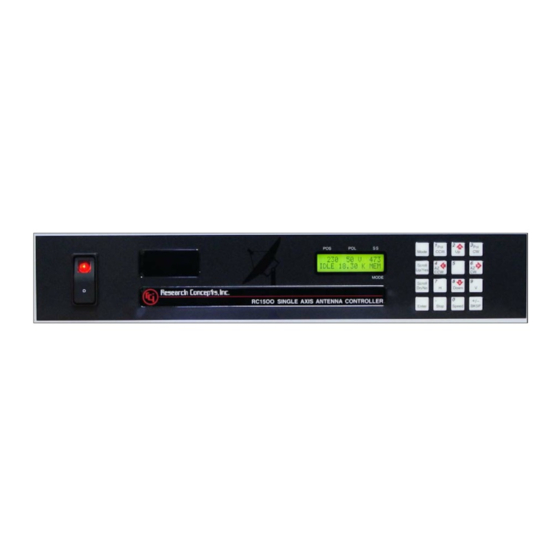
LCD Display
The RC1500 employs a 16 column by 2 row display. The RC2000 employs a 2 x 40 LCD. The
screens of the RC2000 were shrunk to form the RC1500's display. On the RC1500 the
controller's current operating mode is displayed in a three character field in the lower right hand
corner of the display. Here are the three character mode designations...
MAN – Manual mode, AUT – Auto mode, SET – Setup mode, FIX – Fix or Resync mode, REM
– Remote mode, RST – Reset mode, CFG - Configuration, LIM – Limit mode, STP – Track
mode Step Track sub-mode, SEA – Track mode Search sub-mode, MEM – Track mode Program
(or Memory) sub-mode, MNU – Track mode Menu Sub-mode, ERR – Track Mode Error sub-
mode.
Tracking Algorithms
The tracking algorithms of the RC1500 have been simplified relative to those of the RC2000.
Step Tracking - On the 1500 two CONFIG mode items control the performance of the tracker.
The Step Size CONFIG mode item specifies the step size (in actuator position counts) that the
controller takes. The Pk Interval CONFIG item controls the time between peaking operations (in
seconds).
Automatic Search – The limits of the search will be from the (down_limit + 10 cnts) to the
(up_limit – 10 cnts).
Program (or Memory) Track – When memory tracking, the controller will reposition the antenna
whenever the difference between the actual antenna position and the antenna position derived
from the track table differ by (Step Size / 2) or more. Step Size refers to the CONFIG mode
item.
Track Menu – Whenever track mode is active and the time is displayed on the bottom line of the
display the user can hit the 0 key to invoke the track mode menu.
Advertisement
Table of Contents

Subscribe to Our Youtube Channel
Related Manuals for RESEARCH CONCEPTS RC1500B


Summary of Contents for RESEARCH CONCEPTS RC1500B
- Page 1 RC1500 Antenna Controller Implementation The RC1500 is derived from the RC2000C Polar dual axis antenna controller. The RC2000C Polar controller tracks inclined orbit satellites with a polar mount that provides for either a motorized declination or motorized latitude angle adjustment. The feed wiggler system is similar to the variable declination polar mount.
- Page 2 Setup Mode In SETUP mode, for inclined orbits satellites, the controller will prompt for satellite lat/lon and inclination. These values are not used by the tracking algorithms and these prompts will be removed in a future revision of the software. PC Remote Control The controller’s REMOTE mode has not been tested.
- Page 3 Single Axis Tracking with the RC1500B The apparent motion of an inclined orbit satellite appears as a narrow figure 8 pattern aligned perpendicular to the geo-stationary satellite arc. As the inclination of the satellite increases both the height and the width of the figure 8 pattern increase. The single axis tracker can follow the long dimension of the figure 8 but cannot compensate for the width of the figure 8 pattern.
- Page 4 The apparent motion of an inclined orbit satellite repeats itself every 23 hours, 56 minutes, and 4 seconds. The tracking scheme used in the RC1500B employs a step track algorithm to build up a track table which logs the satellite position versus time ( a real time clock powered by a lithium...
- Page 5 The other method is to use the IESS-412 software and parameters available from Intelsat (www.intelsat.com). IESS-412 data is generally only available for Intelsat satellites. An SDP4 program is also available from Research Concepts, Inc. Contact support@researchconcepts.com for more information on this program.
- Page 6 Do not adjust the control axis tilt. 7. When the satellite is at either endpoint of the figure eight pattern adjust the control axis tilt. Research Concepts, Inc. 5420 Martindale Road Shawnee, KS 66218-9680 USA Phone: 913/422-0210 •...
- Page 7 SA-Bus protocol used on the RC1500. 7. The tracking scheme used in the RC1500B employs a step track algorithm to build up a track table which logs the satellite position versus time ( a real time clock powered by a lithium battery is present in the controller).
-
Page 8: Organization Of This Manual
RC1500B for tracking inclined orbit satellites. Chapter 4 concludes with a step by step procedure which guides the user through the entry of track parameters and the initialization of a track on an inclined orbit satellite. -
Page 9: Basic Function Description
An examination of the keyboard in figure 2.2 reveals that many of the keys have 2 or more labels. The function of each key is determined by the current operational mode of the controller. The various modes are discussed in the following section. Figure 2.2 Research Concepts, Inc.; 5420 Martindale; Shawnee, KS 66218 WWW.RESEARCHCONCEPTS.COM... -
Page 10: Arrow Keys
There are two mode groups – operational and programming. Operational modes consist of MAN (manual mode), AUT (auto mode), REM (remote mode), STP (track mode, step track sub-mode), SEA (track mode, search sub-mode), MEM (track mode, Research Concepts, Inc.; 5420 Martindale; Shawnee, KS 66218 WWW.RESEARCHCONCEPTS.COM... -
Page 11: Mode Descriptions
The bottom row of the LCD displays the satellite name and the antenna speed (‘F’ for fast, ‘S’ for slow). While jogging the antenna at slow speed a symbol is displayed to the right of the ‘S’ Research Concepts, Inc.; 5420 Martindale; Shawnee, KS 66218 WWW.RESEARCHCONCEPTS.COM... - Page 12 This mode allows the user to store satellite position and horizontal/vertical polarization values into the controller's non-volatile memory. Once stored in memory, the satellite is available for recall by AUTO mode. Research Concepts, Inc.; 5420 Martindale; Shawnee, KS 66218 WWW.RESEARCHCONCEPTS.COM...
-
Page 13: Select Satellite
A SENSOR error indicates backwards movement of the pot. Any antenna drive error condition can be reset by pressing the key designated on the bottom line of the display. Errors are covered in chapter 6. DELETE SELECT SATELLITE Research Concepts, Inc.; 5420 Martindale; Shawnee, KS 66218 WWW.RESEARCHCONCEPTS.COM... - Page 14 The CONFIG mode item can be modified using the numeric keypad to key in a new value. For the value to be accepted the entry must be terminated by the hitting ENTER key. The Research Concepts, Inc.; 5420 Martindale; Shawnee, KS 66218 WWW.RESEARCHCONCEPTS.COM...
-
Page 15: Mode Access
1. When enabled, REMOTE mode can be activated either via the MODE key or by the receipt of a command on the serial port. Note that most commands received via the serial port may be processed while TRACK mode is active. Research Concepts, Inc.; 5420 Martindale; Shawnee, KS 66218 WWW.RESEARCHCONCEPTS.COM... - Page 16 AutoPol system during installation is covered in more detail in chapter 3, and the CONFIG mode prompts which enable and specify the polarity of the AutoPol input are described in Chapter 5 in the CONFIG mode section. Research Concepts, Inc.; 5420 Martindale; Shawnee, KS 66218 WWW.RESEARCHCONCEPTS.COM...
- Page 17 If the unit does not power up in LIMITS mode the installer should perform a system reset to place the controller into a known state before proceeding with the installation. Research Concepts, Inc.; 5420 Martindale; Shawnee, KS 66218 WWW.RESEARCHCONCEPTS.COM...
-
Page 18: Mechanical And Electrical Installation
The antenna actuator interface is described in this section. Terminal 1 of connector J2 is labeled. 4) A DB-9 female connector (J3) for the SA-Bus compatible remote control interface. Interfacing to the RC1500’s remote control connector is described in the appendices. Research Concepts, Inc.; 5420 Martindale; Shawnee, KS 66218 WWW.RESEARCHCONCEPTS.COM... - Page 19 28 and 22 volts being applied to the antenna drive motors as a function of motor current and wire gauge. The tables take into account the controller output loading and resistive losses in the conductors. Research Concepts, Inc.; 5420 Martindale; Shawnee, KS 66218 WWW.RESEARCHCONCEPTS.COM...
- Page 20 If the shield is allowed to come in contact with earth ground at the antenna ground currents could flow in the shield which could induce noise in the sensor input circuitry. Research Concepts, Inc.; 5420 Martindale; Shawnee, KS 66218 WWW.RESEARCHCONCEPTS.COM...
- Page 21 14 or 16 AWG conductors for motor current and a shielded triple with bare drain wire for the sense lines all enclosed in a common insulating jacket – this type of cable works well with the RC1500. Research Concepts, Inc.; 5420 Martindale; Shawnee, KS 66218 WWW.RESEARCHCONCEPTS.COM...
- Page 22 RC1500B Single Axis Tracking Antenna Controller Chapter 3 Installation/Setup Figure 3.1 RC1500 Back Panel Diagram Figure 3.2 Reed Sensor Diagram Research Concepts, Inc.; 5420 Martindale; Shawnee, KS 66218 WWW.RESEARCHCONCEPTS.COM...
-
Page 23: Polarization Control
Polarotor provides no position feedback to the controller so the controller cannot tell if a Polarotor is actually connected to the system or not. Once the controller is configured for Polarotor operation, the installer should insure that the controller does not think that the Research Concepts, Inc.; 5420 Martindale; Shawnee, KS 66218 WWW.RESEARCHCONCEPTS.COM... - Page 24 Contact the factory for more information. If the current rating of the RC2KPOL motor drive outputs is not sufficient for a given application, please contact the factory for other options. Research Concepts, Inc.; 5420 Martindale; Shawnee, KS 66218 WWW.RESEARCHCONCEPTS.COM...
- Page 25 Centering the Pot The procedure outlined here may be used to center the feed's range of travel within the pot's mechanical limits. Research Concepts, Inc.; 5420 Martindale; Shawnee, KS 66218 WWW.RESEARCHCONCEPTS.COM...
- Page 26 Figure 3.4 depicts the connection of a rotating feed device with the RC1500. Note that the potentiometer interface cable’s drain wire is connected to the Signal Return terminal (1) of connector J4. Research Concepts, Inc.; 5420 Martindale; Shawnee, KS 66218 WWW.RESEARCHCONCEPTS.COM...
- Page 27 MUST INCREASE. If this is not the case, the wires attached to the connector J4 terminals labeled 3 (REF) and 1 (RTN) must be reversed. Note that the shield must always be connected to the RTN terminal. Research Concepts, Inc.; 5420 Martindale; Shawnee, KS 66218 WWW.RESEARCHCONCEPTS.COM...
- Page 28 CW and CCW limit. Return to CONFIG mode, and enter these new limits for Rotating Feed CW Limit (the lower value) and Rotating Feed CCW limit (the greater value). Research Concepts, Inc.; 5420 Martindale; Shawnee, KS 66218 WWW.RESEARCHCONCEPTS.COM...
Need help?
Do you have a question about the RC1500B and is the answer not in the manual?
Questions and answers