Table of Contents
Troubleshooting

Related Manuals for RESEARCH CONCEPTS RC2000A DUAL AXIS


Summary of Contents for RESEARCH CONCEPTS RC2000A DUAL AXIS
- Page 1 RC2000A DUAL AXIS ANTENNA CONTROLLER Contents Subject to Change 08 June 2010 ESEARCH ONCEPTS, 5420 ARTINDALE 66218-9680 USA HAWNEE ANSAS 913.422.0210 WWW.RESEARCHCONCEPTS.COM Support@ResearchConcepts.com...
-
Page 3: Table Of Contents
TABLE OF CONTENTS TABLE OF CONTENTS CHAPTER 1 INTRODUCTION Organization of this Manual Before You Begin Version Identification CHAPTER 2 BASIC FUNCTION DESCRIPTION Front Panel Operating Modes Changing Modes with the MODE Key Mode Access Expert Access AutoPol Sticky Key Jog CHAPTER 3 INSTALLATION/SETUP Before You Begin... - Page 4 4.10.4 Geo Elevation Position 4.10.5 Azimuth and Elevation Slow Speed Codes 4.10.6 Azimuth and Elevation Angle Display 4.10.7 Polarization Motor Option 4.10.8 Azimuth and Elevation Drive Options 4.10.9 Expert Access Flag 4.10.10 Reset System Data 4.11 LIMITS Mode 4.12 POL LIMITS Mode CHAPTER 5 SPECIFICATIONS CHAPTER 6...
- Page 5 1.1.1 Single Frequency Band Potentiometer Adjustment 1.1.2 Dual Frequency Band Potentiometer Adjustment 1.2 Checking the AGC Pot Adjustments 1.2.1 AGC Above Threshold for Noise Input Test 1.2.2 AGC Input Below Threshold for Active Satellite Transponder Test 1.2.3 AGC Input Saturated for Active Satellite Transponder Test 1.2.4 What to do if Problems are Found 2.0 SIGNAL STRENGTH PEAKUP 2.1 Enabling Peakups and Configuring Peakup Parameters...
- Page 7 REVISION HISTORY 3.3.92 v 1.11 * Updated satellite list. * Revised antenna anti-reversal algorithm to function properly for short moves. 4.8.92 v 1.21 Effective S/N E1015, 1018 and thereafter * Setup mode modified to allow movement of the antenna. * For modified polar mounts, the elevation position can be displayed relative to the geosynchronous position.
- Page 8 * The azimuth and elevation angle display system has been modified to accept negative offset values, and the definition of the angle display scale factors has been modified. The scale.exe PC program was replaced with scale2.exe. * The azimuth slow speed system is essentially disabled if the AZIM SLOW SPEED is set to 254. The elevation slow speed system is disabled if the ELEV SLOW SPEED is set to 254.
- Page 9 9.19.00 v 2.30/ v2.31 Effective S/N 3342 The satellite list has been upgraded. The user can modify the operation of the runaway alarm sensing system via the values assigned to the Azim Fast Deadband and Elev Fast Deadband CONFIG mode items. Each axis can be configured separately.
- Page 10 06.08.10 Software v. 4.3x Changed cover page to show date instead of software revision. Embedded Appendix I into body of manual. New Appendix I Signal Strength Peakup...
-
Page 12: Chapter 1 Introduction
Chapters 4 and 6 will probably be the only ones consulted by the user to handle the routine chores of adding new satellites and deleting old ones. Research Concepts, Inc. • 5420 Martindale Road • Shawnee, Kansas • 66218-9680 • USA www.researchconcepts.com... -
Page 13: Before You Begin
‘w’ specifies the satellites that can be seen from western longitudes (North and South America) ‘e’ specifies the satellites that can be seen from eastern longitudes (Europe, Africa, Asia, Australia) Research Concepts, Inc. • 5420 Martindale Road • Shawnee, Kansas • 66218-9680 • USA www.researchconcepts.com... -
Page 14: Chapter 2 Basic Function Description
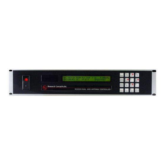
An examination of the keyboard in figure 2.2 reveals that many of the keys have 2 or more labels. The function of each key is determined by the current mode of the controller. The various modes are discussed in the following section. Research Concepts, Inc. • 5420 Martindale Road • Shawnee, Kansas • 66218-9680 • USA www.researchconcepts.com... - Page 15 Note that all of these keys are not active simultaneously. The function of each key is dependent on the current mode of the controller. In some modes certain keys are ignored. Research Concepts, Inc. • 5420 Martindale Road • Shawnee, Kansas • 66218-9680 • USA www.researchconcepts.com...
-
Page 16: Operating Modes
Once stored in memory, the satellite is available for recall by AUTO mode. When SETUP mode is invoked the user peaks the antenna up on Research Concepts, Inc. • 5420 Martindale Road • Shawnee, Kansas • 66218-9680 • USA www.researchconcepts.com... - Page 17 In this mode the antenna can be moved at slow speed about the azimuth axis through the use of the AZ CCW and AZ CW keys and the azimuth slow speed code can be adjusted by using the SCROLL Research Concepts, Inc. • 5420 Martindale Road • Shawnee, Kansas • 66218-9680 • USA www.researchconcepts.com...
- Page 18 In this mode the user can set the polarization limits for the optional polarization motor. The user will be able to access this mode only if the Rotating Research Concepts, Inc. • 5420 Martindale Road • Shawnee, Kansas • 66218-9680 • USA www.researchconcepts.com...
-
Page 19: Changing Modes With The Mode Key
The AutoPol feature should not be used with feeds that receive both horizontal and vertical polarizations simultaneously. Research Concepts, Inc. • 5420 Martindale Road • Shawnee, Kansas • 66218-9680 • USA www.researchconcepts.com... -
Page 20: Sticky Key Jog
MANUAL mode. The Sticky Key Jog will be enabled until the user exits MANUAL mode by hitting the Mode key, the controller is powered down, or a remote command is received that causes activation of REMOTE mode. Research Concepts, Inc. • 5420 Martindale Road • Shawnee, Kansas • 66218-9680 • USA www.researchconcepts.com... -
Page 21: Chapter 3 Installation/Setup
Reset System Data CONFIG mode item. 4. At the Reset System Data screen enter the same 5 digit code followed by the ENTER key. Research Concepts, Inc. • 5420 Martindale Road • Shawnee, Kansas • 66218-9680 • USA www.researchconcepts.com... -
Page 22: Mechanical And Electrical Installation
8 Amps 10 Amps A typical 36 volt actuator will draw 2 to 4 amps and will run at voltages down to about 12 volts. Research Concepts, Inc. • 5420 Martindale Road • Shawnee, Kansas • 66218-9680 • USA www.researchconcepts.com... - Page 23 Date : 02.02.98 AZ DRIVE (2) SKEW AUTOPOL INPUT EL DRIVE (2) SENSORS AGC INPUTS EIC Input Power AGC POTS Figure 3.1 RC2000A Back Panel Research Concepts, Inc. • 5420 Martindale Road • Shawnee, Kansas • 66218-9680 • USA www.researchconcepts.com...
- Page 24 H/V INPUT INPUT AZIMUTH POWER OUTPUT HALL-EFFECT RETURN ASSEMBLY RECEIVER (OPTIONAL) 18- 22 AWG, SHIELDED INPUT ELEVATION POWER HALL-EFFECT RETURN ASSEMBLY Figure 3.3 Hall Effect Diagram Research Concepts, Inc. • 5420 Martindale Road • Shawnee, Kansas • 66218-9680 • USA www.researchconcepts.com...
-
Page 25: Optional Polarization Control
3. Apply power to the feed motor (as in step (3) above) to center the feed in the middle of its range of travel. As the feed rotates, make sure that the shaft of the pot does not turn. Research Concepts, Inc. • 5420 Martindale Road • Shawnee, Kansas • 66218-9680 • USA www.researchconcepts.com... - Page 26 When the feed is adjusted to that position it can receive horizontally and vertically polarized signals simultaneously. In SETUP mode, when a Research Concepts, Inc. • 5420 Martindale Road • Shawnee, Kansas • 66218-9680 • USA www.researchconcepts.com...
- Page 27 ANTENNA POL alarm will activate. Remember, when the polarization is jogged counter-clockwise (with the CCW key), the count MUST increase. If a Research Concepts, Inc. • 5420 Martindale Road • Shawnee, Kansas • 66218-9680 • USA www.researchconcepts.com...
-
Page 28: Setting Azimuth And Elevation Limits
7 key to set an azimuth limit or the 9 key to set an elevation limit. When the counter- clockwise azimuth limit or down elevation limit is set, the position count for the axis is reset to 30. The Research Concepts, Inc. • 5420 Martindale Road • Shawnee, Kansas • 66218-9680 • USA www.researchconcepts.com... -
Page 29: Geo Elev Position
This quantity, referred to as a 'voltage code', varies from 1 to 24. The drive voltage associated with a Research Concepts, Inc. • 5420 Martindale Road • Shawnee, Kansas • 66218-9680 • USA www.researchconcepts.com... -
Page 30: Programming Satellites
Research Concepts, Inc. • 5420 Martindale Road • Shawnee, Kansas • 66218-9680 • USA www.researchconcepts.com... -
Page 31: Angle Display Of Az/El Position Data
1. Determine the antenna latitude and longitude. Obtain a satellite guide and identify the pair of satellites which will be located initially and used to calibrate the angle display. A reasonable Research Concepts, Inc. • 5420 Martindale Road • Shawnee, Kansas • 66218-9680 • USA www.researchconcepts.com... -
Page 32: Autopol
RC2000A only allowed the user to select either a Polarotor type polarization control device or a Rotating Feed. If this altered behaviour of the AutoPol System causes a problem, set the Research Concepts, Inc. • 5420 Martindale Road • Shawnee, Kansas • 66218-9680 • USA www.researchconcepts.com... -
Page 33: Simultaneous Azimuth And Elevation Movement
7. Go to SETUP mode and program in the satellites. If an az/el mount is used, review section 3.6 which describes a procedure for locating satellites that makes use of the RC2000A's ability to display azimuth and elevation position in an angle format. Research Concepts, Inc. • 5420 Martindale Road • Shawnee, Kansas • 66218-9680 • USA www.researchconcepts.com... - Page 34 9. Enable simultaneous azimuth and elevation movement in AUTO mode if the total combined current draw from both actuators is less than 8 amps over all operating conditions///////. Research Concepts, Inc. • 5420 Martindale Road • Shawnee, Kansas • 66218-9680 • USA www.researchconcepts.com...
-
Page 35: Chapter 4 Modes In Depth Function Description
If the closest satellite is a hybrid satellite (both C and Ku band) and the two polarization positions associated with the satellite’s data entry in non-volatile memory are THE SAME, the displayed polarization codes will again be ‘X’ or ‘x’. Research Concepts, Inc. • 5420 Martindale Road • Shawnee, Kansas • 66218-9680 • USA www.researchconcepts.com... -
Page 36: Auto Mode
Expert Access Flag is set. See section 2.5 for more information on the Expert Access Flag. When SETUP mode is activated the following screen is displayed for approximately 5 seconds. Research Concepts, Inc. • 5420 Martindale Road • Shawnee, Kansas • 66218-9680 • USA www.researchconcepts.com... - Page 37 When this screen is displayed the CW and CCW keys may be used to adjust the polarization and the H and V keys may be used to set each polarization. Research Concepts, Inc. • 5420 Martindale Road • Shawnee, Kansas • 66218-9680 • USA www.researchconcepts.com...
-
Page 38: User-Defined Satellite Names
C or Ku band. Remote commands that initiate a peakup specify the band. SAT:AMC 6 BAND: 1 BAND EDIT SCROLL ^v,0-C,1-K,2-CK, ENTER TO SELECT Research Concepts, Inc. • 5420 Martindale Road • Shawnee, Kansas • 66218-9680 • USA www.researchconcepts.com... -
Page 39: Reset Mode
Note that a polarization jammed condition will occasionally register as a sensor error. Polarization movement in the wrong direction should only occur during setup (polarization axis only). Research Concepts, Inc. • 5420 Martindale Road • Shawnee, Kansas • 66218-9680 • USA www.researchconcepts.com... -
Page 40: Delete Mode
BKSP TO CONFIRM, ANY OTHER KEY TO EXIT 5. Press BKSP to recalibrate all stored satellite locations. The system will confirm with the message RE-SYNC ACCOMPLISHED and will return to MANUAL mode. Research Concepts, Inc. • 5420 Martindale Road • Shawnee, Kansas • 66218-9680 • USA www.researchconcepts.com... -
Page 41: Azim Slow Mode
(disabled) then the other two items will not appear in the list of CONFIG mode items. In the descriptions which follow the controlling items and the items, which are controlled by other items will be clearly delineated. Research Concepts, Inc. • 5420 Martindale Road • Shawnee, Kansas • 66218-9680 • USA www.researchconcepts.com... -
Page 42: Autopol
The Comm Port Address item selects the address of the communications port. See the Appendix covering the communications protocol. Valid values for this parameter are 49 to 111. Research Concepts, Inc. • 5420 Martindale Road • Shawnee, Kansas • 66218-9680 • USA www.researchconcepts.com... -
Page 43: Geo Elevation Position
The RC2000A has the ability to display azimuth and elevation position in an angle format. This feature can greatly facility the process of locating satellites for systems which use an elevation over azimuth Research Concepts, Inc. • 5420 Martindale Road • Shawnee, Kansas • 66218-9680 • USA www.researchconcepts.com... - Page 44 Values in the range of 32768 to 65535 are converted to negative offset values for Elev_Offset in the above equations according to the following relationship: Elev_Offset = Elev Offset (CONFIG mode item entered by user) - 65536 Research Concepts, Inc. • 5420 Martindale Road • Shawnee, Kansas • 66218-9680 • USA www.researchconcepts.com...
-
Page 45: Polarization Motor Option
Note that if Two Port polarization control is specified the controller’s AutoPol feature is disabled regardless of the state of the AutoPol CONFIG mode item. Research Concepts, Inc. • 5420 Martindale Road • Shawnee, Kansas • 66218-9680 • USA www.researchconcepts.com... -
Page 46: Azimuth And Elevation Drive Options
The default values of these parameters (as initialized upon system reset) are adequate for use with 36 volt linear actuators. For systems employing linear actuators, it is recommended that Research Concepts, Inc. • 5420 Martindale Road • Shawnee, Kansas • 66218-9680 • USA www.researchconcepts.com... - Page 47 AUTO mode. AZIM MAX POSITION ERROR: 1 CONFIG 0-10 COUNTS ENT,BKSP,SCRLL ^v Research Concepts, Inc. • 5420 Martindale Road • Shawnee, Kansas • 66218-9680 • USA www.researchconcepts.com...
- Page 48 1845 six runaway position counts must be accumulated before an azimuth runaway alarm is triggered. The elevation axis is configured in a similar manner using the Elev Fast Deadband CONFIG mode item. Research Concepts, Inc. • 5420 Martindale Road • Shawnee, Kansas • 66218-9680 • USA www.researchconcepts.com...
- Page 49 The ELEV Position Cnt CONFIG mode item allows setting the current antenna Elevation position to a specific position count value. ELEV POSITION CNT:_ 173 CONFIG 30-65535 ENT,BKSP,SCRLL ^v Research Concepts, Inc. • 5420 Martindale Road • Shawnee, Kansas • 66218-9680 • USA www.researchconcepts.com...
-
Page 50: Expert Access Flag
Elevation Up Limit: 5001 Elevation Limit Checksum: Invalid AutoPol Enable: AutoPol Vpol Level: 1 (Vertical) Simultaneous Az/El Enable: 0 (Disabled) Remote Mode Enable: 0 (Disabled) Research Concepts, Inc. • 5420 Martindale Road • Shawnee, Kansas • 66218-9680 • USA www.researchconcepts.com... - Page 51 Elev Max Position Error: 1 count Elev Auto Retry Attempts: Elev Fast Deadband: 2000 milliseconds Elev Slow Deadband: 800 milliseconds Expert Access Flag: 1 (on - flag set) Research Concepts, Inc. • 5420 Martindale Road • Shawnee, Kansas • 66218-9680 • USA www.researchconcepts.com...
-
Page 52: Limits Mode
NOTE: If LIMITS mode is exited before both endpoints of a limit are set, the RC2000A will ignore the partial limits and retain the previous values. If the controller powers down while LIMITS mode is active, all limit data will be lost. Research Concepts, Inc. • 5420 Martindale Road • Shawnee, Kansas • 66218-9680 • USA www.researchconcepts.com... -
Page 53: Pol Limits Mode
MODE key. Please see section 3.3 before using this mode to set the polarization limits when the optional polarization control motor is present in the system. Research Concepts, Inc. • 5420 Martindale Road • Shawnee, Kansas • 66218-9680 • USA www.researchconcepts.com... -
Page 54: Chapter 5 Specifications
E. Drive supply lines are protected by circuit breakers. The AC input is protected by a 6 amp AGC (fast-blow) fuse at both 115 VAC and 230 VAC. Research Concepts, Inc. • 5420 Martindale Road • Shawnee, Kansas • 66218-9680 • USA www.researchconcepts.com... -
Page 55: Chapter 6 Troubleshooting/Alarm Codes
AZIM COUNT, ELEV COUNT The internal position count has been corrupted. Manually find a satellite and go into RE-SYNC mode to update positions. See Section 4.7 Research Concepts, Inc. • 5420 Martindale Road • Shawnee, Kansas • 66218-9680 • USA www.researchconcepts.com... -
Page 56: Operational Troubleshooting Tips
If the cause of the problem is not found and only one axis is affected, consider replacing the position sense module and/or magnets in the actuator. If both axis are affected the motor drive wires may have Research Concepts, Inc. • 5420 Martindale Road • Shawnee, Kansas • 66218-9680 • USA www.researchconcepts.com... - Page 57 3.2 and 3.3. The AutoPol system should not be enabled when the controller is used with feeds that receive both polarizations simultaneously. WHEN A SATELLITE IS SELECTED VIA AUTO MODE THE CONTROLLER DISPLAYS THE MESSAGE 'ENTRY SELECTED HOLDS INVALID DATA'. Research Concepts, Inc. • 5420 Martindale Road • Shawnee, Kansas • 66218-9680 • USA www.researchconcepts.com...
- Page 58 If the actuator count characteristics are changed, the count values that correspond to the west and up limit will change, as will the positions of all of the satellites. Research Concepts, Inc. • 5420 Martindale Road • Shawnee, Kansas • 66218-9680 • USA www.researchconcepts.com...
-
Page 59: Appendix A - Expert Access / Reset System Data Code
USE CAUTION! For a discussion of expert access, see section 4.10.9. RESET SYSTEM DATA is covered in section 4.10.10 The Code is: 41758 Research Concepts, Inc. • 5420 Martindale Road • Shawnee, Kansas • 66218-9680 • USA www.researchconcepts.com... -
Page 60: Appendix B - Field Upgrading
EPROM package fit into each pin socket and do not bend up under the IC upon insertion. 10. Replace the lid, reinstall the 2000 into the rack, and reconnect the other components of the antenna system. Research Concepts, Inc. • 5420 Martindale Road • Shawnee, Kansas • 66218-9680 • USA www.researchconcepts.com... - Page 61 Replace the fuse with one of the appropriate size for the new operating mains voltage (fuse ratings may be found in the manual and on a back panel placard) Research Concepts, Inc. • 5420 Martindale Road • Shawnee, Kansas • 66218-9680 • USA www.researchconcepts.com...
- Page 62 ________ _____ ______ ______ ______ ________ _____ ______ ______ ______ ________ _____ ______ ______ ______ ________ _____ ______ ______ ______ ________ _____ ______ ______ ______ Research Concepts, Inc. • 5420 Martindale Road • Shawnee, Kansas • 66218-9680 • USA www.researchconcepts.com...
- Page 63 ________ _____ ______ ______ ______ ________ _____ ______ ______ ______ ________ _____ ______ ______ ______ ________ _____ ______ ______ ______ ________ _____ ______ ______ ______ Research Concepts, Inc. • 5420 Martindale Road • Shawnee, Kansas • 66218-9680 • USA www.researchconcepts.com...
-
Page 64: Appendix C - Rs-422 Serial Interface
PC to communicate with up 63 devices. An RS-232 to RS-422 protocol converter (designated RC1KADP) is available from Research Concepts, Inc. The diagrams and schematics at the end of this appendix document the connection of a PC to an RC2500 via an RC1KADP protocol converter. -
Page 65: Appendix D - The Rci Rs422 Interface Specification
Products that are compatible can be linked together over a parallel-connected 4-wire circuit without regard to their particular function. Research Concepts, Inc. • 5420 Martindale Road • Shawnee, Kansas • 66218-9680 • USA www.researchconcepts.com... - Page 66 RS-422. Since the electrical specifications are very similar to EIA standards RS-422 and RS-449, virtually any computer that meets these standards is capable of controlling remote devices. Figure 2 and 3 show RS-422 Master and Slave connections respectively. Research Concepts, Inc. • 5420 Martindale Road • Shawnee, Kansas • 66218-9680 • USA www.researchconcepts.com...
- Page 67 A command message begins with STX (02 hex), the ASCII Start-of-text control character. A message- acknowledged reply begins with ACK (06 hex), the ASCII Acknowledge control character, and a Research Concepts, Inc. • 5420 Martindale Road • Shawnee, Kansas • 66218-9680 • USA www.researchconcepts.com...
- Page 68 Table 1 describes mnemonics used to identify transitions in the state diagram. Research Concepts, Inc. • 5420 Martindale Road • Shawnee, Kansas • 66218-9680 • USA www.researchconcepts.com...
- Page 69 A slave will exit State 1 and enter State 2 (Slave Addressed State) only if STX byte is received. State 2 (Slave Addressed State). In State 2, a slave is waiting to receive the address byte, the second byte of a command message. Research Concepts, Inc. • 5420 Martindale Road • Shawnee, Kansas • 66218-9680 • USA www.researchconcepts.com...
- Page 70 A slave will always exit State 5 and enter Device Idle State, State 1. Research Concepts, Inc. • 5420 Martindale Road • Shawnee, Kansas • 66218-9680 • USA www.researchconcepts.com...
-
Page 71: Appendix E - Rc2000A Communications Protocol
Peakup Status and Signal Strength, bytes 33 – 35, these bytes were added to give the status of peakup operations and indicate signal strength, formerly reserved bytes. Research Concepts, Inc. • 5420 Martindale Road • Shawnee, Kansas • 66218-9680 • USA www.researchconcepts.com... - Page 72 NAK reply is sent to the host. The format of the NAK reply is ... byte 0: Research Concepts, Inc. • 5420 Martindale Road • Shawnee, Kansas • 66218-9680 • USA www.researchconcepts.com...
- Page 73 13: sat_name status - binary data 7 6 5 4 3 2 1 0 0 0 1 0 $ 0 0 _ _ Research Concepts, Inc. • 5420 Martindale Road • Shawnee, Kansas • 66218-9680 • USA www.researchconcepts.com...
- Page 74 0 0 0 'H' polarization code displayed Research Concepts, Inc. • 5420 Martindale Road • Shawnee, Kansas • 66218-9680 • USA www.researchconcepts.com...
- Page 75 H or V in progress byte 30: least significant nibble of alarm status - binary data 7 6 5 4 0 0 1 0 $ a3 a2 a1 a0 Research Concepts, Inc. • 5420 Martindale Road • Shawnee, Kansas • 66218-9680 • USA www.researchconcepts.com...
- Page 76 4) A two port motorized (or rotating) feed with potentiometer position feedback. A two port feed receives horizontal and vertical polarizations simultaneously. 7 6 5 4 3 2 1 0 0 p p p $ s s s s Research Concepts, Inc. • 5420 Martindale Road • Shawnee, Kansas • 66218-9680 • USA www.researchconcepts.com...
- Page 77 'CW' or 'CC'. To obtain the internal polarization position for the rotating feed from this byte and the value in bytes 24 and 25, use the following formula ... internal_position = (byte_24_25_position * 11) + ls_nibble_byte_32 Research Concepts, Inc. • 5420 Martindale Road • Shawnee, Kansas • 66218-9680 • USA www.researchconcepts.com...
- Page 78 5, Azimuth CCW Limit 0 1 1 0 6, Azimuth CW Limit 0 1 1 1 7, Elevation Down Limit 1 0 0 0 8, Elevation Up Limit Research Concepts, Inc. • 5420 Martindale Road • Shawnee, Kansas • 66218-9680 • USA www.researchconcepts.com...
- Page 79 AUTO MOVE COMMAND This command causes the controller to automatically position the antenna in either azimuth and elevation and/or polarization. The command has 3 forms. Research Concepts, Inc. • 5420 Martindale Road • Shawnee, Kansas • 66218-9680 • USA www.researchconcepts.com...
- Page 80 This command jogs the antenna in azimuth or elevation. The command contains 11 bytes. Here is the format of the command; byte 0: byte 1: where A is the RC2000 address byte 2: the command code Research Concepts, Inc. • 5420 Martindale Road • Shawnee, Kansas • 66218-9680 • USA www.researchconcepts.com...
- Page 81 The format of the command is as follows; byte 0: byte 1: where A is the RC2000 address byte 2: the command code byte 3: the polarization movement code Research Concepts, Inc. • 5420 Martindale Road • Shawnee, Kansas • 66218-9680 • USA www.researchconcepts.com...
- Page 82 This accomplishes the same function as the RESET mode of the RC2000: it allows the user to reset the solid state drive circuits if an azimuth or elevation alarm has Research Concepts, Inc. • 5420 Martindale Road • Shawnee, Kansas • 66218-9680 • USA www.researchconcepts.com...
- Page 83 To emulate this characteristic when jogging the controller with the Miscellaneous keystuff command, the reception of a Miscellaneous keystuff command initiates a timer. The key Research Concepts, Inc. • 5420 Martindale Road • Shawnee, Kansas • 66218-9680 • USA www.researchconcepts.com...
- Page 84 13 bytes. Here is the format of the command …. byte 0 byte 1 where A is the RC2000 address byte 2 the command code Research Concepts, Inc. • 5420 Martindale Road • Shawnee, Kansas • 66218-9680 • USA www.researchconcepts.com...
- Page 85 45 - Pol Motor Jog Duration 46 - Expert Mode 47 - Elev Position Cnt 48 – Pol CCW Limit ** 49 – Pol CW Limit ** Research Concepts, Inc. • 5420 Martindale Road • Shawnee, Kansas • 66218-9680 • USA www.researchconcepts.com...
- Page 86 These six bytes are reserved for future expansion. They are currently set to blank characters (20 hex). Byte 17 Byte 18 checksum SAT DATA WRITE COMMAND Research Concepts, Inc. • 5420 Martindale Road • Shawnee, Kansas • 66218-9680 • USA www.researchconcepts.com...
- Page 87 XX is the index of the satellite name being requested. Normally this would be '01' the first time through and then incremented until the 'YY' (YY being the last entry in the list) Research Concepts, Inc. • 5420 Martindale Road • Shawnee, Kansas • 66218-9680 • USA www.researchconcepts.com...
- Page 88 Azimuth target position. The value must be right justified and left padded with zeroes. Values between 0 and 65535 are accepted. A value of zero implies that azimuth movement will not occur. Research Concepts, Inc. • 5420 Martindale Road • Shawnee, Kansas • 66218-9680 • USA www.researchconcepts.com...
- Page 89 A disk containing this program is included with each controller. Research Concepts, Inc. • 5420 Martindale Road • Shawnee, Kansas • 66218-9680 • USA www.researchconcepts.com...
- Page 90 MESSAGE DELIMITERS Here are the delimiters used with SA bus messages, along with their value in hex and decimal. ASCII name hex value decimal value Research Concepts, Inc. • 5420 Martindale Road • Shawnee, Kansas • 66218-9680 • USA www.researchconcepts.com...
-
Page 91: Appendix F - Controlling Antennas Powered By Ac Or Large Dc Motors
12 volts. If 36 volt relays are used the dropping resistor is not needed. A number of products are available from Research Concepts which implement the motor control scheme outline above. See the section below entitled Motor Control Interface Products for a description of these products. - Page 92 On the RC2000 these parameters may be set by the user via CONFIG mode. On the RC1000 these parameters are programmed into the controller's EPROM memory and can only be changed at the factory. Research Concepts, Inc. • 5420 Martindale Road • Shawnee, Kansas • 66218-9680 • USA www.researchconcepts.com...
- Page 93 The RC1000A and RC2000 antenna controllers are not compatible with quadrature pulse sensors. Please see figure 2. Research Concepts, Inc. • 5420 Martindale Road • Shawnee, Kansas • 66218-9680 • USA www.researchconcepts.com...
- Page 94 A number of manufacturers make sensors that may be placed directly between the motor and the gear reducer of the sensor on the C56 flange. Powermation’s #DTK056M1 (phone. 800 811 2691, Research Concepts, Inc. • 5420 Martindale Road • Shawnee, Kansas • 66218-9680 • USA www.researchconcepts.com...
- Page 95 Azimuth Motor RPM: 1750 Range of antenna azimuth movement: 100 degrees From this information the 3-dB beamwidth of the antenna can be determined to be: 0.28 degrees Research Concepts, Inc. • 5420 Martindale Road • Shawnee, Kansas • 66218-9680 • USA www.researchconcepts.com...
- Page 96 0.28 degrees to obtain 17.96 position counts. This satisfies the requirement that there be at least 10 position counts over the antenna’s 3 dB beamwidth. Research Concepts, Inc. • 5420 Martindale Road • Shawnee, Kansas • 66218-9680 • USA www.researchconcepts.com...
-
Page 97: Appendix G Drive Transfer Function
RC2000A Dual Axis Antenna Controller Appendix G Drive Transfer Function APPENDIX G Drive Transfer Function Appendix G Drive Transfer Function Output Drive Current (Amps) Research Concepts, Inc. • 5420 Martindale Road • Shawnee, Kansas • 66218-9680 • USA www.researchconcepts.com... -
Page 98: Appendix H Electrical Diagrams
RC2000A Dual Axis Antenna Controller Appendix H Electrical Diagrams APPENDIX H Electrical Diagrams Drive Board Layout Research Concepts, Inc. • 5420 Martindale Road • Shawnee, Kansas • 66218-9680 • USA www.researchconcepts.com... -
Page 99: Processor Board Layout
RC2000A Dual Axis Antenna Controller Appendix H Electrical Diagrams Processor Board Layout Research Concepts, Inc. • 5420 Martindale Road • Shawnee, Kansas • 66218-9680 • USA www.researchconcepts.com... -
Page 100: Comm Port Wiring Legend
Appendix H Electrical Diagrams Electrical Diagrams Comm Port Wiring Legend Research Concepts, Inc. • 5420 Martindale Road • Shawnee, Kansas • 66218-9680 • USA Research Concepts, Inc. • 5420 Martindale Road • Shawnee, Kansas • 66218-9680 • USA www.researchconcepts.com www.researchconcepts.com... -
Page 101: Rc1Kadp Conversion
RC2000A Dual Axis Antenna Controller Appendix H Electrical Diagrams RC1KADP Conversion Research Concepts, Inc. • 5420 Martindale Road • Shawnee, Kansas • 66218-9680 • USA www.researchconcepts.com... -
Page 102: Rc1Kadp Schematic Rc2Kpol Schematic
Appendix H Appendix H Electrical Diagrams Electrical Diagrams RC1KADP Schematic Research Concepts, Inc. • 5420 Martindale Road • Shawnee, Kansas • 66218-9680 • USA Research Concepts, Inc. • 5420 Martindale Road • Shawnee, Kansas • 66218-9680 • USA www.researchconcepts.com www.researchconcepts.com... -
Page 103: Rc2Kpol Schematic
Appendix H Appendix H Electrical Diagrams Electrical Diagrams RC2KPOL Schematic Research Concepts, Inc. • 5420 Martindale Road • Shawnee, Kansas • 66218-9680 • USA Research Concepts, Inc. • 5420 Martindale Road • Shawnee, Kansas • 66218-9680 • USA www.researchconcepts.com www.researchconcepts.com... -
Page 104: Rc2Khpp Schematic Processor Board Schematic
Appendix H Appendix H Electrical Diagrams Electrical Diagrams RC2KHPP Schematic Research Concepts, Inc. • 5420 Martindale Road • Shawnee, Kansas • 66218-9680 • USA Research Concepts, Inc. • 5420 Martindale Road • Shawnee, Kansas • 66218-9680 • USA www.researchconcepts.com www.researchconcepts.com... -
Page 105: Processor Board Schematic
Appendix H Appendix H Electrical Diagrams Electrical Diagrams Processor Board Schematic Research Concepts, Inc. • 5420 Martindale Road • Shawnee, Kansas • 66218-9680 • USA Research Concepts, Inc. • 5420 Martindale Road • Shawnee, Kansas • 66218-9680 • USA www.researchconcepts.com www.researchconcepts.com... -
Page 106: Drive Board Schematic
Appendix H Appendix H Electrical Diagrams Electrical Diagrams Drive Board Schematic Research Concepts, Inc. • 5420 Martindale Road • Shawnee, Kansas • 66218-9680 • USA Research Concepts, Inc. • 5420 Martindale Road • Shawnee, Kansas • 66218-9680 • USA www.researchconcepts.com www.researchconcepts.com... -
Page 107: Appendix I Signal Strength Peakup
2.1.2. 1.1.1 Single Frequency Band Potentiometer Adjustment The following steps are performed when the controller is in MANUAL mode. Research Concepts, Inc. • 5420 Martindale Road • Shawnee, Kansas • 66218-9680 • USA www.researchconcepts.com... - Page 108 If the AGC has POSITIVE polarity and the signal strength is too low, turn the OFFSET pot counter- clockwise. If the AGC has POSITIVE polarity and the signal strength is too high, turn the OFFSET pot clockwise. Research Concepts, Inc. • 5420 Martindale Road • Shawnee, Kansas • 66218-9680 • USA www.researchconcepts.com...
-
Page 109: Dual Frequency Band Potentiometer Adjustment
Be sure to connect the ground return of the controller to a ground on the receiver. See figure 3.1. Note that if both AGC channels will be utilized, connect the Signal Strength output of the receiver Research Concepts, Inc. • 5420 Martindale Road • Shawnee, Kansas • 66218-9680 • USA www.researchconcepts.com... - Page 110 C or Ku? ____. In the following steps, when instructed to position the antenna ‘RCV1 - off satellite – weak band’ align the antenna with the ____ Band satellite found in step 2 (use the band Research Concepts, Inc. • 5420 Martindale Road • Shawnee, Kansas • 66218-9680 • USA www.researchconcepts.com...
-
Page 111: Checking The Agc Pot Adjustments
The receiver is tuned to an inactive transponder and the AGC input is above the appropriate Threshold. In this case the controller will attempt to peak the antenna because the AGC input is above Research Concepts, Inc. • 5420 Martindale Road • Shawnee, Kansas • 66218-9680 • USA www.researchconcepts.com... -
Page 112: Agc Above Threshold For Noise Input Test
AGC input channels, perform the test on both receivers. From MANUAL mode, the Scroll Up/Down keys can be used to select the AGC input which is displayed. Research Concepts, Inc. • 5420 Martindale Road • Shawnee, Kansas • 66218-9680 • USA www.researchconcepts.com... -
Page 113: What To Do If Problems Are Found
CONFIG mode items are valid, a peakup is initiated. Note that invalid Peakup related CONFIG mode items will result in display of a flashing ‘PEAKUP CONFIG’ alarm message on the bottom row of the controllers LCD. Research Concepts, Inc. • 5420 Martindale Road • Shawnee, Kansas • 66218-9680 • USA www.researchconcepts.com... -
Page 114: Peakup Holdoff
(measured in step 3) the controller will make another step downward and again measure the signal strength. This process will continue until the controller makes a step that results in Research Concepts, Inc. • 5420 Martindale Road • Shawnee, Kansas • 66218-9680 • USA www.researchconcepts.com... -
Page 115: Peakup Errors
Moisture in the form of clouds, fog, or precipitation contribute to fading. The changes in signal strength associated with fading can occur over periods of Research Concepts, Inc. • 5420 Martindale Road • Shawnee, Kansas • 66218-9680 • USA www.researchconcepts.com... -
Page 116: Step Size Selection
C Band El Step Size, C Band Az Step Size, K Band El Step Size, and K Band Az Step Size. Section 3.5.5 tabulates recommended step sizes (in position counts for a number of antennas. 2.5.1 Azimuth and Elevation Step Size Calculation Research Concepts, Inc. • 5420 Martindale Road • Shawnee, Kansas • 66218-9680 • USA www.researchconcepts.com... -
Page 117: Pointing Error (Degrees) Given Pointing Loss (Db) Relationship
Pointing Loss 2.4 meters 0.41 / 0.58 0.14 / 0.19 3.1 meters 0.32 / 0.45 0.11 / 0.15 3.8 meters 0.26 / 0.36 0.09 / 0.12 Research Concepts, Inc. • 5420 Martindale Road • Shawnee, Kansas • 66218-9680 • USA www.researchconcepts.com... -
Page 118: Determining The Antenna Azimuth And Elevation Count Per Degree Characteristic118
Inclination field in ANTENNA.EXE should be set to 0.0. RESEARCH CONCEPTS, INC Phone (913) 469-4125 Copyright 1992 Antenna Location Latitude: 47.40 Longitude: -122.30 Mag Variation: -18.73 Satellite Data Longitude: -87.00 Inclination: 0.00 Research Concepts, Inc. • 5420 Martindale Road • Shawnee, Kansas • 66218-9680 • USA www.researchconcepts.com... - Page 119 Antenna Latitude 25° 30° 35° 40° 45° 50° Elevation Angle for satellite 60.8° 55.0° 49.4° 43.7° 38.2° 32.7° whose longitude value is the same antenna. Research Concepts, Inc. • 5420 Martindale Road • Shawnee, Kansas • 66218-9680 • USA www.researchconcepts.com...
-
Page 120: Recommended Step Sizes For Various Antennas
(0.5 dB steps/1.0 dB steps) degrees degrees degrees degrees degrees degrees latitude latitude latitude latitude latitude latitude C Band 22/31 19/27 16/23 15/22 14/20 14/19 12/17 Ku Band 7/10 Research Concepts, Inc. • 5420 Martindale Road • Shawnee, Kansas • 66218-9680 • USA www.researchconcepts.com... - Page 121 Type of Equipment: Satellite Antenna Controllers Model No’s.: RC2000A Year of Manufacture: 1998 In order to meet the EMC directive, fully shielded, properly connected cable is required for all connections. Research Concepts, Inc. • 5420 Martindale Road • Shawnee, Kansas • 66218-9680 • USA www.researchconcepts.com...
- Page 122 WARRANTY One Year Limited Warranty Research Concepts, Inc., RCI, warrants to the original purchaser this product shall be free from defects in material and workmanship for one year, unless expressed otherwise, from the date of the original purchase. During the warranty period, RCI will provide, free of charge, both parts and labor necessary to correct such defects.
Need help?
Do you have a question about the RC2000A DUAL AXIS and is the answer not in the manual?
Questions and answers