Table of Contents
Advertisement
Quick Links
Advertisement
Table of Contents

Related Manuals for RESEARCH CONCEPTS RC4500


Summary of Contents for RESEARCH CONCEPTS RC4500
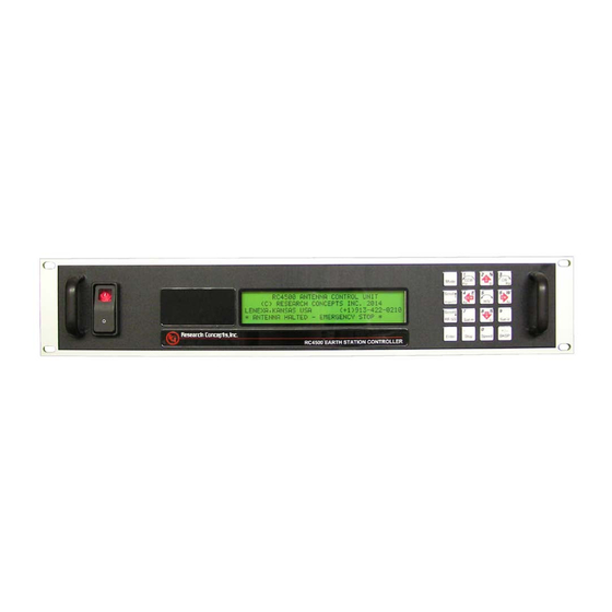
- Page 1 RC4500 ANTENNA CONTROLLER USER’S MANUAL RESEARCH CONCEPTS INC. 9501 Dice Lane Lenexa, Kansas 66215 USA VOICE: (913) 422-0210 FAX: (913) 422-0211 www.researchconcepts.com support@researchconcepts.com Contents subject to change Serial No________...
- Page 3 REVISION HISTORY DATE MODIFICATION SW VERSION INITIALS 27 SEP 2014 Initial release 1.09 20 NOV 2014 Initial update 1.09 5 JUN 2015 Update Chapter 2, replace board-stack 1.09 information with separate rack-mount and embedded information 17 JUN 2015 Update of Chapter 3 screens. 1.09 18 JUN 2015 Corrected discrepancies in the AZ Jam...
- Page 4 LIMITED WARRANTY New Products Research Concepts, Inc., RCI, warrants to the original purchaser this product shall be free from defects in material and workmanship for one year, unless expressed otherwise, from the date of the original purchase. During the warranty period, RCI will provide, free of charge, both parts and labor necessary to correct such defects.
-
Page 5: Table Of Contents
TABLE OF CONTENTS 1.0 INTRODUCTION ..............................1 1.1 M ............................. 1 ANUAL RGANIZATION 1.2 RC4500 F .............................. 3 EATURES 1.3 H ............................4 ARDWARE VERVIEW 1.4 S ........................... 5 OFTWARE NITIALIZATION 1.5 S ..............................8 PECIFICATIONS 2.0 BASIC OPERATION ............................9 2.1 U... - Page 6 3.4.2.4.2 El Resolver ..............................57 3.4.2.4.3 Az Resolver ..............................58 4.0 SOFTWARE CONFIGURATION / INSTALLATION ................... 59 4.1 S ..........................60 OFTWARE NITIALIZATION 4.1.1 Mount LAT/LON Definition ........................60 4.1.2 Define Antenna Size ........................... 61 4.1.3 Define Polarization Equipment ........................61 4.1.4 Define System Time ............................
- Page 7 APPENDIX B – MOUNT SPECIFIC DATA APPENDIX C – ENCLOSURE SPECIFIC DATA The following appendices describe optional features of the RC4500. These appendices will be included in the manual if the option is present. APPENDIX REM : SERIAL-BASED REMOTE CONTROL...
- Page 8 APPENDIX DVB : INTEGRATED DVB RECEIVER APPENDIX BCN : INTEGRATED BEACON RECEIVER...
-
Page 9: Introduction
Appendix C, titled "ENCLOSURE SPECIFIC DATA", details mechanical and electrical details on how the RC4500 is packaged. This appendix may not be supplied from RCI if the boardset is not packaged in an RCI provided enclosure. Separate appendices describe optional features of the RC4500. Example optional appendices that could... - Page 10 Latitude and longitude of the mount are presented in degree/minute/second (38°56’23 N) format. When referring to a particular RC4500 mode of operation, that mode’s name will be capitalized – ex. MENU. Throughout the RC4500 manual and software, the latitude, longitude and true heading of the mount are collectively referred to as the mount’s “position”.
-
Page 11: Rc4500 Features
- Optional Single-Mode Fiber Optic remote control -Motor drive interface via Antenna Interface Unit OR via internal motor drive board for direct-drive of low voltage DC motors The following picture shows an example of the RC4500 board-set mounted in a 2U standard rack mount enclosure. -
Page 12: Hardware Overview
RC4500 Antenna Controller Chapter 1 Introduction 1.3 Hardware Overview The following figure is a block diagram showing the major components of the RC4500 boardset and how they interface with a typical antenna system. Individual interfaces will be described in detail in Chapter 3. -
Page 13: Software Initialization
RC4500 Antenna Controller Chapter 1 Introduction 1.4 Software Initialization Upon powering up the RC4500, there are two identification screens that are displayed during a five second software start-up. RC4000 FIRMWARE BOOTLOADER (c) RESEARCH CONCEPTS INC. 2014 SN:0 Last FW:AB-VWXYZ BL:1.1 Please wait ... - Page 14 Step & Memory Track supported Step & Memory plus Two Line Element set tracking supported Remote Control Options The RC4500 may provide optional support for controlling the mount from a remote (away from the front panel) location. CATEGORY DESIGNATOR DESCRIPTION...
- Page 15 RC4500 Antenna Controller Chapter 1 Introduction RECEIVER OPTIONS The RC4500 may provide optional support for controlling multiple integrated satellite receivers from two different connectors. The RC4500 can support the integrated DVB receiver along with two additional receivers. Receiver 1 Options The Receiver 1 option specifies support for both the RCI DVB receiver (integrated on the options board) along with an additional receiver via the REC1 connector.
-
Page 16: Specifications
RC4500 Antenna Controller Chapter 1 Introduction 1.5 Specifications RC4500 ACU Physical Board Stack Rack Mount Embedded 19” x 3.5” x 17” Size 1/8” x 7” x 3 ¾” 9 ½” x 7 ½” x 3 ½” 2U Rack Encl.,17” Deep Weight 2.6 lbs. -
Page 17: Basic Operation
2.0 BASIC OPERATION 2.1 User Interface The RC4500 allows multiple options for mechanizing the user interface. This section describes software operations as if the most basic "front panel" interface (keypad and LCD) was present. NOTE: the “front panel” interface may be mechanized in multiple ways:... -
Page 18: Keypad Usage
Chapter 2 Basic Operation 2.1.1 Keypad Usage The keypad provides a flexible method of controlling the functionality of the RC4500. While each RC4500 mode has different requirements for user input, the use of the keypad remains consistent throughout all modes. - Page 19 RC4500 Antenna Controller Chapter 2 Basic Operation KEY LABEL SPECIFIC FUNCTION GENERAL FUNCTION Momentary push switches between modes within group. Mode No specific function Button held for 3 seconds switches between operational and programming groups. Momentary push also exits sub-mode screens.
- Page 20 RC4500 Antenna Controller Chapter 2 Basic Operation KEY LABEL SPECIFIC FUNCTION GENERAL FUNCTION <1> Supplies “6” for numeric entry. Move azimuth axis clockwise in Az CW MANUAL mode Supplies West for longitude entry. (123°45W) <1> Supplies “7” for numeric entry.
-
Page 21: Data Entry
Chapter 2 Basic Operation 2.1.2 Data Entry Many RC4500 screens request some type of user input. This section provides instructions on the entry of various types of data. Selection From List ( <0-9>SELECT ) When the user is prompted to select an action from a displayed list, pressing the numbered key corresponding to the desired action will initiate the action. - Page 22 RC4500 Antenna Controller Chapter 2 Basic Operation Time is entered in HH:MM:SS format and date in DD/MM/YY format.
-
Page 23: Display Layout
WAITING FOR NEXT PEAKUP <0>MENU MODE TITLE: in the upper right corner the title of the current RC4500 mode is displayed – in this example TRACK designates that the RC4500 is currently in track mode. NOTE: if the mode title is preceded by an exclamation point ( ! ), the mode was initiated by a remote command. -
Page 24: Menu Structure
Basic Operation 2.1.4 Menu Structure The functionality of the RC4500 is achieved by placing the controller in the desired mode of operation. The following figure shows the hierarchy of the RC4500’s modes. Each mode has a unique display screen that presents the information applicable to that mode’s operation. - Page 25 RC4500 Antenna Controller Chapter 2 Basic Operation...
-
Page 26: Operating Mode
ENTER LATITUDE DEGREES (+dd.dddd) After entering the latitude and longitude, the RC4500 will transition to the INITIAL MODE. NOTE: One of the first actions that should be taken when integrating an RC4500 ACU is to define the antenna’s latitude and longitude. -
Page 27: Menu Mode Basics
RC4500 Antenna Controller Chapter 2 Basic Operation 2.2.2 MENU Mode Basics A full detailed description of the MENU mode screen and all sub-modes can be found in section 5.1.2. 1-SETUP 2-RECALL 3-DELETE MENU 4-MOVETO <0-9>SELECT <MODE>MANUAL 14:37:23 MENU mode allows the user to select one of the listed actions (sub-modes.) Pressing the <1>... -
Page 28: Programming Mode
The Programming Mode consists of the CONFIG mode and MAINT (maintenance) mode. These are the two modes that will be used during installation and calibration of the RC4500. This section is intended to be a very abbreviated guide to the Programming Mode screens and an in-depth description of each screen should be reviewed in section 5.2 PROGRAMMING... -
Page 29: Mechanical & Electrical Installation
This chapter describes the RC4500 and common external devices that may be used for integrating an antenna system. This chapter is split into four main parts. The first part describes the RC4500 in a standard rack-mount enclosure, interfacing to an AIU. The second part describes the RC4500 in a standard rack-mount enclosure, directly driving low voltage DC motors. -
Page 30: Rack Mount Enclosure To Aiu
The RC4500 enclosure is available as a standard rack mount chassis that occupies two rack units (2U). The front panel is mounted via four (4) 10-32 screws. Due to the length and weight of the RC4500, much strain can be put on the faceplate. To help alleviate stress on the front panel mounting, additional mounting points accepting 10-32 screws are provided on each side of the unit. -
Page 31: Electrical Interface
Mechanical & Electrical Installation 3.1.2 Electrical Interface This section provides cabling requirements for interfacing to the RC4500 rack mount ACU. Note that the cables should be made long enough to allow the unit to be open while still connected to the system. -
Page 32: Power Entry
J11 is an IEC-C14 male power socket on the back panel for supplying AC power to the RC4500. The RC4500 is shipped from the factory with a line cord with an IEC-C13 plug. The RC4500 can accept 85 to 265 VAC at 50/60 Hz. -
Page 33: Auxiliary I/O
A +24 VDC unregulated output (750mA max) referenced to the RC4500 chassis ground, is also available. Each limit input on connector J6 is rated for 24VDC and draws approximately 5mA @ 24VDC input. - Page 34 RC4500 Antenna Controller Chapter 3 Mechanical & Electrical Installation Connector J6 Auxiliary I/O Signal Descriptions: Pin # Signal Name Description 3, 5, 6, AZ CW Limit Return, These pins are the return signals associated with various limit 7, 8 EL DOWN Limit Return, inputs found on the J6 connector.
- Page 35 This terminal is internally connected to the Drive Common pins found on the Antenna I/O connector (J7 pins 2, 5, 8). Ground This pin is tied (internally) to the ground return of the RC4500’s 24VDC system power supply. (typically not used) 24VDC This pin is tied (internally) to the RC4500’s 24VDC system power...
-
Page 36: Antenna I/O
MAINTENANCE RETURN circuit the controller disables antenna control and displays the ‘Maintenance’ alarm message. This terminal also powers all of the RC4500’s isolated output drive circuits (AZ CCW/CW, EL DOWN/UP, POL CCW/CW, AZ/EL FAST and DRIVE ENABLE.) 17 to 27 volts DC is required to power the controller’s output circuits. The current that powers the... - Page 37 RC4500 Antenna Controller Chapter 3 Mechanical & Electrical Installation Connector J7 Antenna I/O Signal Descriptions: Pin # Signal Name Description 1, 3, 4, AZ CW Command, Pull down type current drivers (outputs). 6, 7, 9 AZ CCW Command, The controller turns the driver ON to command the antenna to EL UP Command, move in the direction associated with the driver.
- Page 38 Summary Limit Input Summary/AZ CCW Limit input. Versions of the RC4500 that are plug compatible with the Vertex 7134 interpret this signal as a Summary Limit. When current in this circuit is interrupted, the controller assumes that one of the antenna’s limit switches is active.
- Page 39 RC4500 Antenna Controller Chapter 3 Mechanical & Electrical Installation Connector J7 Antenna I/O Signal Descriptions (continued): Pin # Signal Name Description Emergency Stop Status Emergency Stop input. When current flows in this circuit, the controller assumes that the AIU Emergency Stop is not active. If the controller senses that the Emergency Stop is active, the controller disables antenna control and displays the ‘Emergency Stop’...
- Page 40 ‘Maintenance’ alarm message. This pin also powers all of the RC4500’s isolated output drive circuits (AZ CCW/CW, EL DOWN/UP, POL CCW/CW, AZ/EL FAST, and DRIVE ENABLE).
-
Page 41: Sensors
RC4500 Antenna Controller Chapter 3 Mechanical & Electrical Installation 3.1.2.5 Sensors J1 is a 9 pin D subminiature female receptacle that optionally allows a Polarization potentiometer to provide position sensing to the RC4500. Pin # Description Polarization Potentiometer Shield Polarization Potentiometer Wiper... -
Page 42: Agc
A shielded pair, such as Alpha 1292C, should be used to minimize external noise pickup on the signal strength line. The shield should be connected at the RC4500 system ground and open circuited at the receiver. -
Page 43: Rf Input
Setting the IP address of the target device to 192.168.1.2 with a subnet mask of 255.255.255.0 will usually allow a quick connection to the RC4500. If you’ve reset the IP address and no longer have any record of it, please call Research Concepts, Inc. for an IP address recovery procedure. -
Page 44: Spare Connectors
3.1.2.10 Serial Remote Control When a serial remote control option is included, the spare connector J12 is utilized. The RC4500 may be configured to communicate either by the RS-232 or RS-422 standards. -
Page 45: Rack Mount Enclosure W/ Direct Drive To Dc Motors
The RC4500 enclosure is available as a standard rack mount chassis that occupies two rack units (2U). The front panel is mounted via four (4) 10-32 screws. Due to the length and weight of the RC4500, much strain can be put on the faceplate. To help alleviate stress on the front panel mounting, additional mounting points accepting 10-32 screws are provided on each side of the unit. -
Page 46: Electrical Interface
RC4500 Antenna Controller Chapter 3 Mechanical & Electrical Installation 3.3.2 Electrical Interface Under Development The electrical interface section is currently under development and will be updated as soon as possible. For additional questions, please contact the factory. -
Page 47: Embedded Controller To Aiu
3.3.1 Mechanical Mounting The RC4500 available in an embedded enclosure that is typically installed within a larger enclosure of an AIU (Antenna Interface Unit), typically the AIU7. Detailed information regarding the mechanical and electrical interface specific to connecting an AIU7 to an antenna may be found in the AIU7 Appendix. -
Page 48: Electrical Interface
Mechanical & Electrical Installation 3.3.2 Electrical Interface This section provides cabling requirements for interfacing to the RC4500 embedded ACU. The following sections supply a schedule of connection requirements. The following diagram shows the typical location of the cables and connectors located on the end panel of the RC4500 enclosure. -
Page 49: Dc Power Input
3_22SHLDUV.) The black conductor is DC Common and the Red conductor is +24VDC. The White conductor is not used. In a typical installation of the RC4500 ACU inside an AIU7, the DC Power Input cable is connected to the +24VDC switching power supply located in the upper left corner of the enclosure back panel. -
Page 50: Resolver Inputs
<1> The colors shown assume the use of Belden 8777 cable. When installed in an AIU7, the resolver cables from the RC4500 may be terminated on user-accessible terminal blocks to allow a more convenient installation. Below is a photograph that depicts a typical... -
Page 51: I/O And Limits
3.3.2.3 I/O and Limits The I/O and Limits cable is used by the RC4500 to interface with the AIU relay board primarily to produce drive commands and receive limit switch status. A cable such as Belden 9948 (RCI p/n CBL-25_22) is used. -
Page 52: Integrated Ip Option
MAINTENANCE RETURN circuit the controller disables antenna control and displays the ‘Maintenance’ alarm message. This terminal also powers all of the RC4500’s isolated output drive circuits (AZ CCW/CW, EL DOWN/UP, POL CCW/CW, AZ/EL FAST and DRIVE ENABLE.) 17 to 27 volts DC is required to power the controller’s output circuits. The current that powers the output drive circuits flows out of the DRIVE COMMON terminals back to the AIU. -
Page 53: Board-Stack In Outdoor Enclosure W/ Direct Drive To Dc Motors
Chapter 3 Mechanical & Electrical Installation 3.4 Board-stack in Outdoor Enclosure w/ Direct Drive to DC Motors This section describes the mechanical and electrical interfaces of the RC4500 in a weatherproof, outdoor enclosure. 3.4.1 Mechanical Mounting The RC4500 is available as a board-stack mounted inside an outdoor weatherproof enclosure. The following diagram shows the typical dimensions of the outdoor enclosure. -
Page 54: Electrical Interface
RC4500 Antenna Controller Chapter 3 Mechanical & Electrical Installation 3.4.2 Electrical Interface... - Page 55 RC4500 Antenna Controller Chapter 3 Mechanical & Electrical Installation...
-
Page 56: Ac Power Input
The power supply of the RC4500 can automatically accommodate single phase AC input between 85 to 265 VAC and between 47 to 63 Hz. The power supply card (located on the bottom of the board-stack) will convert the AC input into 24 VDC power for use by the drive section and for powering the other board-set cards. -
Page 57: Motor Drive
Mechanical & Electrical Installation 3.4.2.2 Motor Drive The RC4500 drive section is designed to drive azimuth, elevation and polarization motors up to 24 volt DC. The absolute maximum allowed motor current is 10 Amps. The motor drive module supports IR compensation, current limiting, adjustable acceleration / deceleration profiles, dual speed operation and dynamic braking. -
Page 58: Computing And Interface Board
RC4500 Antenna Controller Chapter 3 Mechanical & Electrical Installation 3.4.2.3 Computing and Interface Board The Computing/Interface Board is part of the board-stack located behind the Local User Interface Panel. The following connections to the Computing/Interface Board may be made during installation. -
Page 59: Receiver 1
RC4500 Antenna Controller Chapter 3 Mechanical & Electrical Installation 3.4.2.3.1 Receiver 1 The J3 connector is allocated to support various types of receivers. The mating connector for the Computing/Interface Board position J3 is Phoenix p/n 1881383. The flexible I/O includes:... -
Page 60: Polarization Sensors
RC4500 Antenna Controller Chapter 3 Mechanical & Electrical Installation 3.4.2.3.2 Polarization Sensors J13 provides a double row of pins. The top 16 pins are designated "J13A" and are typically allocated to supporting potentiometer and limit switch feedback from the polarization axis. The mating connector for the Computing/Interface Board position J13A is Phoenix p/n 1952403. -
Page 61: Azimuth Limits
RC4500 Antenna Controller Chapter 3 Mechanical & Electrical Installation 3.4.2.3.3 Azimuth Limits J14 provides a double row of pins. The top 16 pins are designated "J14A" and are typically allocated to supporting limit switch feedback from the azimuth axis. The mating connector for the Computing/Interface Board position J14A is Phoenix p/n 1952403. -
Page 62: Elevation Limits
If present, the elevation up switch must be open when the elevation axis has reached the up limit. If the elevation up limit switch cable is severed, the RC4500 will think that the elevation axis is at the up limit. -
Page 63: Resolver Board
Mechanical & Electrical Installation 3.4.2.4 Resolver Board The Resolver Board allows an RC4500-based ACU to be able to sense axis positions via resolvers by utilizing resolver-to-digital converters. Note: The J4 Pol Resolver connector and PCB components are not installed on the Resolver Board when... -
Page 64: Pol Resolver
3.4.2.4.1 Pol Resolver NOTE: SHIELDED CABLE IS REQUIRED FOR THE RESOLVER CONNECTIONS. THE SHIELD MUST BE CONNECTED TO THE RC4500 CHASSIS GROUND AT THE CONTROLLER AND MUST NOT BE CONNECTED AT THE ANTENNA. Three shielded twisted-pairs for each resolver are required to minimize noise pickup and cross-coupling, which can result in antenna positioning errors. -
Page 65: El Resolver
3.4.2.4.2 El Resolver NOTE: SHIELDED CABLE IS REQUIRED FOR THE RESOLVER CONNECTIONS. THE SHIELD MUST BE CONNECTED TO THE RC4500 CHASSIS GROUND AT THE CONTROLLER AND MUST NOT BE CONNECTED AT THE ANTENNA. Three shielded twisted-pairs for each resolver are required to minimize noise pickup and cross-coupling, which can result in antenna positioning errors. -
Page 66: Az Resolver
3.4.2.4.3 Az Resolver NOTE: SHIELDED CABLE IS REQUIRED FOR THE RESOLVER CONNECTIONS. THE SHIELD MUST BE CONNECTED TO THE RC4500 CHASSIS GROUND AT THE CONTROLLER AND MUST NOT BE CONNECTED AT THE ANTENNA. Three shielded twisted-pairs for each resolver are required to minimize noise pickup and cross-coupling, which can result in antenna positioning errors. -
Page 67: Software Configuration / Installation
Software Configuration / Installation 4.0 SOFTWARE CONFIGURATION / INSTALLATION Once the cabling between the RC4500 and the position sensors, AIU, motors and any other required peripherals has been made, certain startup and configuration items should be set for optimum performance. This chapter describes how to set these parameters in the RC4500. For a discussion of how to navigate to the CONFIG mode, MAINTENANCE mode, etc., see... -
Page 68: Software Initialization
Software Configuration / Installation 4.1 Software Initialization From the factory, the RC4500 will arrive with all configuration items in the default state. To return the RC4500 to this default state, the use of the RESET DEFAULTS configuration screen may be used. See section 5.2.1.3.11... -
Page 69: Define Antenna Size
RC4500 Antenna Controller Chapter 4 Software Configuration / Installation 4.1.2 Define Antenna Size The CONFIG-SYSTEM DEFINITION screen contains configuration items for the ACU system, including defining the antenna size. MODE:2 ANT SIZE: 500 CONFIG-SYSTEM ANT LOOK:1 DRIVE:3 ANTENNA SIZE <1-9999 CM>... -
Page 70: Define System Time
RC4500 Antenna Controller Chapter 4 Software Configuration / Installation 4.1.4 Define System Time An additional recommended step is to set the date/time within the ACU. The Date/Time will be set to UTC at the factory but the internal clock may drift several seconds per month. -
Page 71: Initial Calibration
If an AIU is used, it should already have been wired such that the axes are all moving in the correct direction with local jog controls (if any.) Whether the motors are controlled via an AIU or directly via the RC4500 low-voltage DC motor drive, the motor directions should be verified before continuing. -
Page 72: Fast And Slow Speed Settings
AIU. There is no fine speed adjustment in the RC4500 for this case. The second system controls the fast and slow speeds directly from the low-voltage motor drive circuit within the RC4500. Both fast and slow speeds may be fine tuned for each axis that is being directly driven by the RC4500. -
Page 73: Determine Offset Angles & Reference Voltages
RC4500 Antenna Controller Chapter 4 Software Configuration / Installation 4.2.3 Determine Offset Angles & Reference Voltages This section is used to determine the offset angles of the position sensor (typically a resolver or potentiometer) for each axis. A proper offset angle will allow the displayed angle to match the antenna’s true position. -
Page 74: Azimuth Offset Angle
(either True North or South). 2) True Heading Angle – this is the azimuth angle (TRUE) most commonly displayed for the RC4500. This represents the true (not magnetic) heading that the antenna is pointing. For fixed-based applications this is the most common angle used when referring to the antenna’s azimuth position. -
Page 75: Azimuth Offset Angle - Southern Hemisphere
RC4500 Antenna Controller Chapter 4 Software Configuration / Installation TRUE RES OFF a:179.05 180.00 180.00 (-179.05) e:181.14 22.30 22.30 (-158.84) <1-AZ,3-EL>REF <5>LON <7-AZ,9-EL>OFFSET The resulting display shows a displayed angle of 180.00. Calculation: (179.05 – 179.05 + 180.00 = 180.00). -
Page 76: Polarization Reference Voltage And Offset Angle
RC4500 Antenna Controller Chapter 4 Software Configuration / Installation 4.2.3.3 Polarization Reference Voltage and Offset Angle This section describes how to approximately align the polarization axis’ displayed angle to a local horizontal reference. The steps required to accomplish this depends on whether the polarization axis is equipped with a potentiometer or resolver. -
Page 77: Polarization Reference Voltage For Potentiometer
RC4500 Antenna Controller Chapter 4 Software Configuration / Installation The polarity of a waveguide is determined by its narrow dimension. In the diagram, position A shows port 1 as being at the 0.0 degree orientation. In position B, port 2 is at the 0.0 degree orientation. -
Page 78: Polarization Offset For Resolver
RC4500 Antenna Controller Chapter 4 Software Configuration / Installation 4.2.3.3.2 Polarization Offset for Resolver For antennas implementing a resolver for polarization position feedback, a reference position is derived from an offset of the raw resolver angle. First verify that the polarization resolver offset (ROFF) value is set to 0.000 in the CONFIG –... -
Page 79: Scale Factors
. Perform scale factor calibration only if the Appendix B suggests that the scale factor for your particular mount should be characterized. For resolver-based position sensing, the RC4500 utilizes a 16 bit resolver to digital converter which generates a count value from 0 to 65,535. Typically the resolver sensor rotates with the antenna. The resulting “pulse scale factor”... -
Page 80: Polarization Scale Factor
RC4500 Antenna Controller Chapter 4 Software Configuration / Installation 4.2.4.3 Polarization Scale Factor The polarization position sensor most often used is the potentiometer, although a resolver may also be used. The scale factor for the potentiometer is given in degrees per volt, whereas the resolver scale factor is given in pulses per radian. -
Page 81: Verify And Set Limits
The RC4500 also includes soft limits that are used as part of the RC4500’s algorithms with automatic moves, peaking routines, etc. The soft limits don’t actually limit each axis’ travel but are used by software to determine if a calculated pointing solution is outside the mount’s range of movement. - Page 82 Verify the Polarization CCW limit and the Polarization CW limit by manually jogging the antenna (in MANUAL mode) to each limit. Verify that the RC4500 prevents any movement beyond these limits. When each limit is activated, the text “CCW” or “CW” will be displayed to the right of the Polarization position.
-
Page 83: Final Calibration
RC4500 Antenna Controller Chapter 4 Software Configuration / Installation 4.3 Final Calibration 4.3.1 Drive System Checkout This step confirms the configuration of the drive system for all three axes. Manually move the mount to each axis limit and confirm drive current to the motor is shut off when the limit is reached. Also check the displayed position value and confirm that it is reasonable. -
Page 84: Signal Strength Adjustment
Software Configuration / Installation 4.3.2 Signal Strength Adjustment The RC4500 can sense satellite signal strength via the signal strength input circuits (refer to Chapter This section describes how to configure the signal strength input circuits for use with the satellite receivers used for a particular installation. -
Page 85: Operational Presets
5.1.2.1. 4.3.4 Miscellaneous Adjustments LCD Contrast. An LCD contrast potentiometer (R26) is located on the RC4500 computing and interface board. This potentiometer will be set at the factory, but the user may want to adjust its setting for a particular installation’s lighting conditions. -
Page 87: Modes - In Depth Descriptions
MENU mode allows the user to select the modes that implement the RC4500’s automatic movement features. While in either one of these modes, a momentary push of the Mode key will transition the RC4500 to the other mode. - Page 88 RC4500 Antenna Controller Chapter 5 MODES – In Depth Descriptions and V will be defined according to the reference defined in the FEED DEFINITION screen (ie. if REF = H, H = 0 & V = 90 if REF = V, V = 0 & H = 90).
-
Page 89: Menu Mode
RC4500 Antenna Controller Chapter 5 MODES – In Depth Descriptions 5.1.2 Menu Mode MENU mode allows the user to select one of listed modes. Pressing the Mode key will move to MANUAL mode. 1-SETUP 2-RECALL 3-DELETE MENU 4-MOVETO <0-9>SELECT <MODE>MANUAL 14:37:23 MENU mode displays the reference time and time zone in the lower right hand corner. -
Page 90: Setup
<H/V>SELECT RX POLARIZATION <MODE>MENU If the selected satellite is not inclined, the RC4500 will return to MANUAL mode. If an inclined satellite is selected (and the inclined orbit tracking option is present), control will automatically move to the TRACK (5.1.2.5) mode. -
Page 91: Recall
RC4500 Antenna Controller Chapter 5 MODES – In Depth Descriptions 5.1.2.2 Recall Satellites which have been stored in the controller's non-volatile memory (via SETUP) can be recalled from the RECALL mode. RECALL NAME INCL BAND TRK 90.0W OFF ---- <SCR>THRU LIST <ENTER>SELECT <MODE>EXIT... -
Page 92: Moveto
RC4500 Antenna Controller Chapter 5 MODES – In Depth Descriptions 5.1.2.4 MoveTo The MOVETO mode is intended to provide an easy way to move the antenna to a certain position for doing testing such as cutting antenna patterns. This mode is also useful for tuning up automatic movements. -
Page 93: Track
MODES – In Depth Descriptions 5.1.2.5 Track *** NOTE: The Track screen will only be available on RC4500 controllers that were purchased with the inclined orbit tracking option. *** The optional TRACK mode may be entered via the SETUP or RECALL modes if the selected satellite has been described as having an inclined orbit. -
Page 94: Programming Group
5.2.1 Configuration Mode The CONFIG mode allows users to view and/or modify various controller parameters and to enable or disable certain features. Many configuration items are used to customize the RC4500 to work with a particular installation. The CONFIG mode groups configuration items into screens containing between 1 to 10 individual items. - Page 95 RC4500 Antenna Controller Chapter 5 MODES – In Depth Descriptions GROUP TITLE GROUP DESCRIPTION SECTION NORMAL ACCESS ITEMS EXPERT ACCESS PERMISSION SETS EXPERT ACCESS PERMISSION 5.2.1.1.1 TLE 1 DATA LINE 1 – TWO LINE ELEMENT SET 5.2.1.1.2 TLE 2 DATA LINE 2 –...
-
Page 96: Normal Access Items
RC4500 Antenna Controller Chapter 5 MODES – In Depth Descriptions 5.2.1.1 NORMAL ACCESS ITEMS The configuration groups contained in the “Normal” access level allows the user to change items that would typically be required to be changed following system configuration. -
Page 97: Tle 1 Data
As the name implies, Two Line Element set data is described by two lines of data each with 69 characters. The RC4500 uses one screen to show each line of data. The top line of each screen identifies which line is being displayed (TLE1 or TLE2). -
Page 98: Tle 2 Data
As the name implies, Two Line Element set data is described by two lines of data each with 69 characters. The RC4500 uses one screen to show each line of data. The top line of each screen identifies which line is being displayed (TLE1 or TLE2). -
Page 99: Installation Access Items
These items specify the antenna's elevation range of travel. The angles refer to the raw resolver angle (see section 5.1.1.) When the RC4500 calculates an antenna pointing solution based on satellite longitude in MOVETO mode, it checks these values to see if the dish can be physically moved to that position. -
Page 100: Azimuth Calibration
These items specify the antenna's azimuth range of travel. The angles refer to the raw resolver angle (see section 5.1.1.) When the RC4500 calculates an antenna pointing solution based on satellite longitude in MOVETO mode, it checks these values to see if the dish can be physically moved to that position. -
Page 101: Polarization Calibration
RC4500 Antenna Controller Chapter 5 MODES – In Depth Descriptions 5.2.1.2.3 Polarization Calibration VREF:2.500 OFF: 0.000 CONFIG-POL CCW:-100.000 CW: 100.000 SF: 40.000 ZERO DEG VOLTAGE <1.000–4.000 VOLTS> VREF: ZERO DEG VOLTAGE <1.000 - 4.000 VOLTS> The pol_reference_voltage defines the voltage present when the polarization axis is in its center of motion. -
Page 102: Feed Definition
RC4500 Antenna Controller Chapter 5 MODES – In Depth Descriptions 5.2.1.2.4 Feed Definition CONFIG-FEED TYPE:1 LO:10750 BAND:1 REF:0 <0>CIRCULAR <1>SINGLE <2>DUAL TYPE: <0>CIRCULAR <1>SINGLE <2>DUAL The polarization_type configuration item specifies the configuration of the feed drive. This item will be used by the controller to determine the appropriate automatic movement of the polarization axis. -
Page 103: External Sig Factors
LOCK TIME <0.0 – 10.0 SECONDS> This item defines how long the RC4500 will wait after each step before sampling signal strength. Increasing this value may be required to allow equipment such as a modem to generate an AGC output. -
Page 104: Location Reset
RC4500 Antenna Controller Chapter 5 MODES – In Depth Descriptions 5.2.1.2.6 Location Reset RESET CODE: CONFIG-LOC <5 DIGIT CODE>ENTER 12345 TO RESET The LOCATION RESET screen is used to reset the stored antenna location. After the 5 digit code <12345> is entered, a confirmation screen will appear. Press the “BKSP” key to accept. -
Page 105: Super-User Access Items
<2-MENU 3-MANUAL> MODE: <2-MENU 3-MANUAL> This item specifies to which of the modes listed the RC4500 will go to upon power up. ANT SIZE: ANTENNA SIZE <1-9999 CM> This item specifies the size of the reflector in centimeters. For example, a 5.9 ft. diameter reflector (1.8m) would require a value of 180 (cm.) be specified. -
Page 106: Azimuth Angle Movement
RC4500 Antenna Controller Chapter 5 MODES – In Depth Descriptions 5.2.1.3.2 Azimuth Angle Movement The CONFIG-AZ ANG screen contains configuration items for calibrating large automatic azimuth movements based on angle (potentiometer or resolver-based) position feedback. See the Drive System theory section 6.2.3. -
Page 107: Azimuth Count Movement
RC4500 Antenna Controller Chapter 5 MODES – In Depth Descriptions 5.2.1.3.3 Azimuth Count Movement The CONFIG-AZ COUNT screen contains items for configuring automatic movements based on sensor count (resolver or pulse) azimuth position feedback. CONFIG-AZ COUNT FAST/SLOW: 50 COAST: MAX ERROR: 1 TRIES: 3 FAST/SLOW THRESHOLD <0-999 COUNTS>... -
Page 108: Azimuth Drive Parameters
CURRENT LIMIT <0-10 AMPS*10, 0=OFF > The CL setting represents the percentage of maximum current that the motor drive will allow to the motor for the azimuth axis. The motor drive of the RC4500 will supply up to 10 Amps by default. ACC: ACCELERATION <0-999 MSEC>... - Page 109 RC4500 Antenna Controller Chapter 5 MODES – In Depth Descriptions RUN: RUNAWAY SLOP <0.0-10.0 DEG, 0.0=OFF > The azim_runaway_slop_item specifies the amount of movement that may be sensed before a runaway condition is declared when the antenna is not supposed to be moving.
-
Page 110: Elevation Angle Movement
RC4500 Antenna Controller Chapter 5 MODES – In Depth Descriptions 5.2.1.3.5 Elevation Angle Movement The CONFIG-EL ANG screen contains configuration items for calibrating large automatic elevation movements based on angle (inclinometer or resolver-based) position feedback. See the Drive System theory section 6.2.3. -
Page 111: Elevation Count Movement
RC4500 Antenna Controller Chapter 5 MODES – In Depth Descriptions 5.2.1.3.6 Elevation Count Movement The CONFIG-EL COUNT screen contains items for configuring automatic movements based on sensor count (resolver or pulse) elevation position feedback. CONFIG-EL COUNT FAST/SLOW: 50 COAST: MAX ERROR: 1 TRIES: 3 FAST/SLOW THRESHOLD <0-999 COUNTS>... -
Page 112: Elevation Drive Parameters
CURRENT LIMIT <0-10 AMPS*10, 0=OFF > The CL setting represents the percentage of maximum current that the motor drive will allow to the motor for the azimuth axis. The motor drive of the RC4500 will supply up to 10 Amps by default. ACC: ACCELERATION <0-999 MSEC>... - Page 113 RC4500 Antenna Controller Chapter 5 MODES – In Depth Descriptions RUN: RUNAWAY SLOP <0.0-10.0 DEG, 0.0=OFF > The elev_runaway_slop_item specifies the amount of movement that may be sensed before a runaway condition is declared when the antenna is not supposed to be moving.
-
Page 114: Polarization Angle Movement
RC4500 Antenna Controller Chapter 5 MODES – In Depth Descriptions 5.2.1.3.8 Polarization Angle Movement The CONFIG-POL ANG screen contains configuration items for calibrating polarization movements based on potentiometer position feedback. See the Drive System theory section 6.2.3. CONFIG-POL ANG FAST/SLOW: 2.000 COAST:0.300... -
Page 115: Polarization Drive Parameters
CURRENT LIMIT <0-10 AMPS*10, 0=OFF> The CL setting represents the percentage of maximum current that the motor drive will allow to the motor for the polarization axis. The motor drive of the RC4500 will supply up to 10 Amps by default. ACC: ACCELERATION <0-999 MSEC>... - Page 116 RC4500 Antenna Controller Chapter 5 MODES – In Depth Descriptions RUN: RUNAWAY SLOP <0.0 – 10.0 DEG, 0.0=OFF> The pol_runaway_slop_item specifies the amount of movement that may be sensed before a runaway condition is declared when the antenna is not supposed to be moving.
-
Page 117: Track Factors
RC4500 Antenna Controller Chapter 5 MODES – In Depth Descriptions 5.2.1.3.10 Track Factors *** NOTE: The Track Factors screen will only be available on RC4500 controllers that were purchased with the inclined orbit tracking option. *** SEARCH: 3 CONFIG-TRACK MAX ERROR: 3... - Page 118 RC4500 Antenna Controller Chapter 5 MODES – In Depth Descriptions conclude that the smallest value of Max Track Error leads to the tightest track. When the value of this parameter is reduced to a point where the peakup azimuth or elevation step sizes approach the value of the mechanical hysteresis (slop) of the antenna mount, the controller can not peakup properly.
- Page 119 RC4500 Antenna Controller Chapter 5 MODES – In Depth Descriptions AZDP: AZ/EL DELTA FACTOR <0.5 – 1.5> The track_az_dp_item allows step sizes to be biased for different effective azimuth and elevation diameters. The default value of 1.0 will calculate steps assuming the antenna’s azimuth and elevation diameters are the same.
-
Page 120: Shake
RC4500 Antenna Controller Chapter 5 MODES – In Depth Descriptions 5.2.1.3.11 Shake AZ 1: -40.0 2: 50.0 3: 0.0 CONF-SHAKE EL 1: 30.0 2: 40.0 3: -67.5 CYCLE: 100 PL 1: -10.0 2: 10.0 3: 0.0 DELAY: MOVE 1 AZIM <-180.0/180.0>... -
Page 121: Reset Defaults
RC4500 Antenna Controller Chapter 5 MODES – In Depth Descriptions 5.2.1.3.12 Reset Defaults RESET CODE: CONFIG-DEFAULTS <5 DIGIT CODE>RESET TO FACTORY DEFAULTS The CONFIG-DEFAULTS screen is used to reset the controller's memory. Access to this item is allowed only when the Expert Access level is set to SUPER-USER. To reset the system memory, the user must key in a 5 digit code followed by the ENTER key. -
Page 122: Maintenance Items
RC4500 Antenna Controller Chapter 5 MODES – In Depth Descriptions 5.2.2 Maintenance Items This screen provides a menu system for selecting the various maintenance screens described in the following paragraphs. Pressing the Mode key from this screen will return the controller to the CONFIG- MENU screen. -
Page 123: Analog To Digital Voltage
RC4500 Antenna Controller Chapter 5 MODES – In Depth Descriptions 5.2.2.1 Analog to Digital Voltage The AD VOLTAGES maintenance screen shows the current voltage levels sensed at the microcontroller’s analog to digital inputs. There are too many input channels to show all voltages on one screen, so the user is prompted to choose either 10 bit or 12 bit resolution voltages. -
Page 124: Bit Adc Voltages
Note that all of the analog to digital channels have some associated scaling and conditioning circuitry in the RC4500. Therefore the voltages seen at this screen may not be exactly the same as the input voltages external to the RC4500. -
Page 125: Drive Error Resets
RC4500 Antenna Controller Chapter 5 MODES – In Depth Descriptions 5.2.2.2 Drive Error Resets 1-AZIM: JAMMED DRIVE RESET 2-ELEV: RUNAWAY <4>RESET PULSE COUNT 3- POL: OK (AZ/EL AT STOW) RESET <1-3>AXIS <MODE>EXIT The DRIVE RESET maintenance screen provides the way to reset drive system errors (JAMMED / RUNAWAY / DRIVE) for each axis. -
Page 126: Time Maintenance
OFFSET: 1-DATE 2-TIME 4-ZONE 5-OFFSET SYSTEM: Current date and time as maintained by the RC4500’s real-time clock. DISPLAY: Current “reference” time that will be displayed in several screens (MANUAL, MENU). This time is offset from the system time by the OFFSET number of hours described later. -
Page 127: Gps Communications (Optional)
RC4500 Antenna Controller Chapter 5 MODES – In Depth Descriptions 5.2.2.4 GPS Communications (Optional) The GPS interface is only included as an option under special request. When this option is included, the GPS COMM screen allows the user to ascertain if the GPS receiver is communicating correctly with the RC4000. -
Page 128: Limits Maintenance
<MODE>EXIT The limits maintenance screen shows the current state of each limit switch as sensed by the RC4500’s microcontroller. The state of each limit is shown as 0 if off or 1 if on. An * is displayed if the particular limit switch is not relevant for the particular mount (there is no POL STOW switch in the above example). -
Page 129: Shake
RC4500 Antenna Controller Chapter 5 MODES – In Depth Descriptions 5.2.2.6 Shake The SHAKE mode performs repetitive mount movements. The SHAKE mode is for support of mount testing and for automatic mount demonstrations such as trade shows. The SHAKE mode is only available if expert access is enabled. -
Page 130: System Information
RC4500 Antenna Controller Chapter 5 MODES – In Depth Descriptions 5.2.2.7 System Information Selecting the “Stop/.” key from the MAINTENANCE screen triggers a display of various system/software information. Serial Number: 0 SYSTEM INFO Firmware: RC4K-TEST-GTRSB Version: 0.07 BN: EG0926 Lat: 38.9557 Lon: -94.7544... -
Page 131: Resolver Offset Calculator
RC4500 Antenna Controller Chapter 5 MODES – In Depth Descriptions 5.2.2.7 Resolver Offset Calculator... -
Page 133: Support
6.1.1 Limit Switches The various limit switches serve as safety interlocks to prevent mount damage. The RC4500 checks for limit conditions via both software and a Programmable Logic Device. The limit switches connect directly to the Antenna Interface Unit via the relay board. - Page 134 The AIU transmits limit status information back to the RC4500 through low impedance current loops. These current loops drive the LED portion of opto-isolators in the RC4500. An open circuit between the RC4500 Limit Switch Feedback opto-isolator and the AIU will result in a limit indication.
-
Page 135: Motor Drive
4.2.2. 6.1.4 GPS The interface between the RC4500 and the optional GPS receiver is via an RS-232 serial port. The data stream from the GPS receiver is parsed in multiple places in order to receive latitude, longitude and time data. The following messages may be displayed when the RC4500 is attempting to receive data from the GPS: ** NO GPS PRESENT **. -
Page 136: Alarm Displays
6.1.5.1 FLASH / NVRAM VERSION MISMATCH If the RC4500 recognizes a mismatch in the stored data (antenna mount type data) then this error code will appear. The only time this error typically would occur is during a software change in the ACU. A system reset to defaults may clear this error (5.2.1.3.11). -
Page 137: Limits Inactive Warning
AIU. The alarm will continue to display until the switch has be deactivated. During the time when this alarm is active, the RC4500 will not allow any movement of the antenna and will display “* ANTENNA HALTED – EMERGENCY STOP *”. -
Page 138: Acu Topics
Given the mount’s latitude and longitude and the pointing vector to the satellite, the RC4500 calculates the elevation (with respect to local horizontal) required. Feedback from the resolver mounted on the elevation... -
Page 139: Timekeeping
System time is maintained by the RC4500’s real time clock. The real-time clock is backed up by battery so that system time is available as soon as the RC4500 powers up. The system time is used to calculate sidereal time for maintaining track tables. Since satellite’s do not experience time shifts (such as from Standard Time to Daylight Savings Time or when moving from one time zone to another), it is recommended that system time not be modified while active track tables are present. -
Page 140: Polarization Control
Support Anti-Reversal In order to save wear on the drive motors, the RC4500 limits how fast an axis may reverse its direction. This mechanism prevents a motor from instantly changing direction before coasting to a stop in the original direction. - Page 141 RC4500 Antenna Controller Appendix A Expert Access Codes APPENDIX A - EXPERT ACCESS CODES To initiate INSTALL ACCESS permission or to RESET SYSTEM DEFAULTS, the user must enter the five digit code: 42458 To initiate SUPER-USER ACCESS permission, the user must enter the five digit code:...
Need help?
Do you have a question about the RC4500 and is the answer not in the manual?
Questions and answers