Table of Contents

Related Manuals for RESEARCH CONCEPTS RC3050


Summary of Contents for RESEARCH CONCEPTS RC3050
- Page 1 RC3050 ANTENNA JOG CONTROLLER USER’S MANUAL Contents subject to change 28 March 2000 RESEARCH CONCEPTS INC. 5420 Martindale Road Shawnee, Kansas 66218-9680 USA (913) 422-0210 support@researchconcepts.com www.researchconcepts.com...
-
Page 3: Table Of Contents
3.3 Programming Group ............................25 3.3.1 Drive Error Resets............................25 3.3.2 Azimuth Reference Voltage ...........................25 3.3.3 Elevation Reference Voltage..........................26 3.3.4 Polarization Reference Voltage........................26 3.3.5 Azimuth and Elevation Limits ........................27 3.3.6 Polarization Limits ............................27 Research Concepts, Inc.; 5420 Martindale Road; Shawnee, Kansas 66218-9680 USA www.researchconcepts.com... - Page 4 4.3 Schematics ................................33 5.0 TROUBLESHOOTING.................... 38 APPENDIX A – MOUNT SPECIFIC DATA..............40 APPENDIX B – DC MOTOR CONTROLLER............... 43 APPENDIX C – RC3050 TEST DATA SHEET ............. 53 Research Concepts, Inc.; 5420 Martindale Road; Shawnee, Kansas 66218-9680 USA www.researchconcepts.com...
- Page 5 Manual; Data Test Sheet Updated WARRANTY INFORMATION Research Concepts, Inc. (RCI) warrants to the original purchaser, this product shall be free from defects in material and workmanship for one year, unless expressed otherwise, from the date of the original purchase.
-
Page 7: Introduction
RC3050 provides manual control of azimuth, elevation and polarization axes. Optionally the RC3050 may automatically stow and deploy the antenna and control a waveguide switch. The design and function of the RC3050 is derived from the RC3000 Satellite Locator / Inclined Orbit Tracking Controller. The RC3050 may be upgraded to the RC3000 configuration. - Page 8 POL, Pol Clockwise Counter-Clockwise (Anti-Clockwise) Down Latitude Longitude Satellite Liquid Crystal Display When referring to a particular RC3050 mode of operation that mode’s name will be capitalized – ex. AUTO. Research Concepts, Inc.; 5420 Martindale Road; Shawnee, Kansas 66218-9680 USA www.researchconcepts.com...
-
Page 9: Rc3050 Features
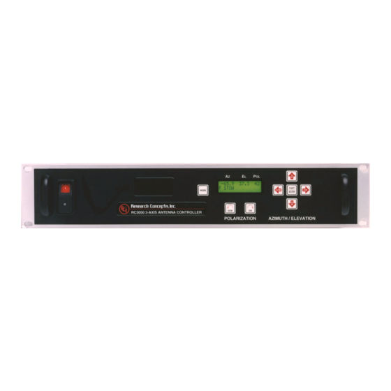
Chapter 1 Introduction 1.2 RC3050 Features The RC3050 antenna controller is designed to provide easy operation of mobile (both vehicle mounted and deployable) mounts. Features provided include: - 3 axes jog operation - Simultaneous azimuth, elevation and polarization angle display... -
Page 10: Theory Of Operation
LIQUID CRYSTAL DISPLAY (LCD). The 2 row by 16 column LCD provides the user interface for monitoring the status of the RC3050 and for entering data. KEYPAD. The 8 key keypad allows the user to enter data and commands to the RC3050. DIGITAL BOARD. The digital board is essentially a small computer containing a microcontroller, memory, real-time clock and circuitry to monitor and drive the keypad and LCD. -
Page 11: System Interface Requirements
- IR compensation to improve load regulation POWER ENTRY MODULE. The power entry module allows the RC3050 to be configured for 115 or 230 VAC operation. POWER TRANSFORMER. The power supply module transforms AC input voltage to a regulated DC voltage for use by the digital and drive boards. -
Page 12: Drive System
Programming Group Functions The programming group modes provide for initial calibration of the controller and also provides a screen for resetting drive error conditions. Calibration screens allow the user to calibrate the RC3050 for use with a particular mount. AZIM VOLT:2.500 <UP>SET (2.489) -
Page 13: System Performance
Anti-Reversal In order to save wear on the drive motors, the RC3050 limits how fast an axis may reverse its direction. This mechanism prevents a motor from instantly changing direction before coasting to a stop in the original direction. -
Page 14: Installation
Installation 2.0 INSTALLATION Proper installation is important if the full capability and accuracy of the RC3050 is to be realized. The procedures that follow will insure the optimum level of performance from all sensors and the system in general. Prior to installation, please review section 1.3.2 (System Interface Requirements) to verify the correct system interfaces are provided. -
Page 15: Equipment Mounting
The RC3050 enclosure is a standard rack mount chassis that occupies two rack units (2U). The front panel is mounted via four (4) 10-32 screws. Due to the length and weight of the RC3050, much strain can be put on the faceplate particularly in a mobile unit. To help alleviate stress on the front panel mounting, additional mounting points accepting 10-32 screws are provided on each side, back and bottom of the unit. -
Page 16: Electronic Clinometer
The inclinometer should be mounted in a location such that it is protected somewhat from blowing rain. Research Concepts, Inc.; 5420 Martindale Road; Shawnee, Kansas 66218-9680 USA www.researchconcepts.com... - Page 17 RC3050 Antenna Controller Chapter 2 Installation Research Concepts, Inc.; 5420 Martindale Road; Shawnee, Kansas 66218-9680 USA www.researchconcepts.com...
-
Page 18: Electrical Connections
J6 is an IEC power connector for supplying AC power to the RC3050. The RC3050 is shipped from the factory with an line cord appropriate for the line voltage selected. If the line cord received with the unit is not appropriate for the power available at the installation site, the installer should check the controller to ensure that the proper line voltage has been selected. -
Page 19: Motor Drive
For azimuth CW movement, terminal G has the higher potential. Elevation H, J For elevation UP movement, terminal H has the higher potential. Polarization A, B For polarization CW movement, terminal A has the higher potential. Research Concepts, Inc.; 5420 Martindale Road; Shawnee, Kansas 66218-9680 USA www.researchconcepts.com... -
Page 20: Drive Sense
Normally, it is not necessary to modify the sensors on the antenna. The antenna manufacturer will insure that the antenna is compatible with the RC3050. This information is provided for informational purposes only. The directional sense of azimuth movement is defined as clockwise (CW) or counter-clockwise (CCW) as viewed by an observer located above the antenna. -
Page 21: Limit Switches
The elevation up switch must be open when the elevation axis has reached the up limit. If the elevation up limit switch cable is severed, the RC3050 will think that the elevation axis is at the up limit. Logic within the RC3050 will not allow the elevation axis to move up if an up limit condition is recognized. -
Page 22: Waveguide Switch
Drive Out 1,2 provide 28 VDC to energize the waveguide switch. NOTE: The RC3050 assumes the waveguide switch’s position 1 is the horizontal (H) position. If the H and V positions need to be reversed, both the position volts (9/10 and 14/15) and the position indicator (3 and 4) lines need to be swapped. -
Page 23: Hand Held Remote
J10 (DB-25 Female) connects to the optional Hand-held remote control (RC8097RC) which allows antenna jog operations independent of the front panel. The remote control is housed in a 3” x 6” x 1.75” aluminum case. The remote control should be connected to the RC3050 with a 25’ multi-conductor cable. -
Page 24: Calibration
Calibration may be done in any area (possibly a shop environment) where the antenna may be moved throughout its entire range of travel. At this point, the installer will have to start operating the RC3050 from the front panel. Section 3 will need to be reviewed to perform the steps described below. -
Page 25: Position Sensor Rigging And Calibration
2.50 volts as possible and secure the collar. After positioning the pot correctly, store the value as described in 3.3.2. This will define to the RC3050’s software the voltage that should be seen when the azimuth axis is in its centerline position. -
Page 26: Azimuth And Polarization Electrical Limits
2.4 Miscellaneous Adjustments LCD Contrast An LCD contrast potentiometer is located on the RC3050 digital board. This potentiometer will be set at the factory but the user may want to adjust its setting for a particular installation’s lighting conditions. Research Concepts, Inc.; 5420 Martindale Road; Shawnee, Kansas 66218-9680 USA... -
Page 27: Detailed Operation
3.0 DETAILED OPERATION 3.1 Operation Overview The functionality of the RC3050 is achieved by placing the controller in the desired mode of operation. The figure shows the hierarchy of the RC3050’s modes. Each mode has a unique display screen that presents the information applicable to that mode’s operation. -
Page 28: Operating Group
RC3050’s automatic movement features. While in either one of these modes, a momentary push of the Mode key will transition the RC3050 to the other mode. Upon powering up the RC3050, an identification screen is displayed for five seconds. The software version data is discussed in 1.2 (Controller Features). -
Page 29: Auto Mode
See appendix A for the deploy position for a particular mount. The automatic movement may be terminated anytime by pressing any key. Following completion of movement to the deploy position, the RC3050 will return to MANUAL mode. 3.2.2.2 Stow 180.0 –12.3 -90... -
Page 30: Waveguide Mode
H position and a “-“ will be shown while going to the V position. Note that after 5 seconds the switching operation will timeout and drive voltage will be stopped if the desired position has not been sensed. Research Concepts, Inc.; 5420 Martindale Road; Shawnee, Kansas 66218-9680 USA www.researchconcepts.com... -
Page 31: Programming Group
The AZIM VOLT screen allows the user to set the reference voltage that defines the centerline of azimuth travel. When this voltage is seen the RC3050 will generate an azimuth position of 0.0 degrees. See the Drive System theory section 1.3.7. -
Page 32: Elevation Reference Voltage
The ELEV VOLT screen performs in the same manner as described for the AZIM VOLT screen. 3.3.4 Polarization Reference Voltage POL VOLT:2.500 <UP>SET (2.482) The POL VOLT screen performs in the same manner as described for the AZIM VOLT screen. Research Concepts, Inc.; 5420 Martindale Road; Shawnee, Kansas 66218-9680 USA www.researchconcepts.com... -
Page 33: Azimuth And Elevation Limits
If a limit is active, a “1” will be displayed. If a limit is not active, a “0” will be displayed. For some mounts, there is no polarization stow switch in which case a “*” will be displayed. Research Concepts, Inc.; 5420 Martindale Road; Shawnee, Kansas 66218-9680 USA www.researchconcepts.com... -
Page 34: Alarm Displays
LOW BATTERY The RC3050 constantly monitors the level of the lithium battery. When the power level is low, this error code will appear. Replace the battery with a Duracell DL2450. Make sure that the unit is unplugged from the AC power before removing the cover to change the battery. -
Page 35: Specifications
(option RC3050HRC), and the ability to auto-deploy and auto- stow (option RC3050ASD). In addition to the features of the RC3050, the RC3000 is an antenna controller which can incorporate sensors that allow it to calculate the antenna pointing solution (azimuth, elevation and polarization angles) required to intercept a given satellite. - Page 36 RC3000 include, PC Remote Control via RS-232 or RS-422, option RC3000CRC, and Inclined-Orbit Satellite Tracking, option RC3000TRK. Further details of the RC3000 product may be found in the RC3000 or RC3050 cutsheets, the RC3000 product selector guide, or by contacting RCI. Antenna Interface The RC3000 locator is designed to control an elevation over azimuth type antenna.
- Page 37 The user may provide these externally using micro switches and steering diodes if needed. Some A versions support a fairing deploy switch rather than the pol stow limit. Research Concepts, Inc.; 5420 Martindale Road; Shawnee, Kansas 66218-9680 USA www.researchconcepts.com...
- Page 38 J9-GPSDB9 female on dongle GPS & cable, (RC3000GPS) J9-FG DB9 female on dongle FG Compass & cable (RC3000FG) DB25 female Handheld Remote Control (RC3000HRC) F female Block LNB signal for auto peak Research Concepts, Inc.; 5420 Martindale Road; Shawnee, Kansas 66218-9680 USA www.researchconcepts.com...
-
Page 39: Schematics
RC3050 Antenna Controller Chapter 4 Specifications 4.3 Schematics Research Concepts, Inc.; 5420 Martindale Road; Shawnee, Kansas 66218-9680 USA www.researchconcepts.com... - Page 40 RC3050 Antenna Controller Chapter 4 Specifications Research Concepts, Inc.; 5420 Martindale Road; Shawnee, Kansas 66218-9680 USA www.researchconcepts.com...
- Page 41 RC3050 Antenna Controller Chapter 4 Specifications Research Concepts, Inc.; 5420 Martindale Road; Shawnee, Kansas 66218-9680 USA www.researchconcepts.com...
- Page 42 RC3050 Antenna Controller Chapter 4 Specifications Research Concepts, Inc.; 5420 Martindale Road; Shawnee, Kansas 66218-9680 USA www.researchconcepts.com...
- Page 43 RC3050 Antenna Controller Chapter 4 Specifications Research Concepts, Inc.; 5420 Martindale Road; Shawnee, Kansas 66218-9680 USA www.researchconcepts.com...
-
Page 44: Troubleshooting
Failure of a limit switch to activate properly may be due to the limit switch mechanism itself, cabling to the limit switch or failure of the RC3050 to sense the limit switch correctly. Isolating the problem to the RC3050 or switch/wiring may be accomplished by jumpering the appropriate pins on the J3 connector. - Page 45 If +12 VDC is present, the limit switch sensing logic may be checked by jumpering between the appropriate pins and noting if the limit switch condition is sensed correctly by the RC3050. The state of the limit switches should be monitored via the Limit (3.3.5,.6) screens. The following table shows which pins to jumper and state that should be seen via the Limits Maintenance screen.
-
Page 46: Appendix A - Mount Specific Data
Mount Specific Data APPENDIX A – MOUNT SPECIFIC DATA VERTEX SMK / DMK Mount Variations The following table lists the different mounts supported by the RC3050 and the required software model number required to support that mount. MODEL # MOUNT... - Page 47 18.5 (1) The elevation stow position does not correspond to an indicated angle since the stow position is outside the effective range of the electronic clinometer. The RC3050 will drive down until it reaches the elevation stow switch Research Concepts, Inc.; 5420 Martindale Road; Shawnee, Kansas 66218-9680 USA...
- Page 48 Mount Specific Data APPENDIX B - MOUNT SPECIFIC DATA AVL TECHNOLOGIES Mount Variations The following table lists the different mounts supported by the RC3050 and the required software model number required to support that mount. MODEL # MOUNT DESCRIPTION 1.2 m. ERA 1.5 m.
-
Page 49: Appendix B - Dc Motor Controller
The following pages are reprints of the manuals for the two different motor speed controllers used in the RC3050. The AMC drive is used for the RC3050A (low voltage DC) and the KBPB drive is used for the RC3050B (high voltage DC). - Page 50 RC3050 Antenna Controller Appendix C DC Motor Controller Please see additional page inserts for Appendix C, following this page. Research Concepts, Inc.; 5420 Martindale Road; Shawnee, Kansas 66218-9680 USA www.researchconcepts.com...
-
Page 51: Appendix C - Rc3050 Test Data Sheet
________________________ V(Slow) _______________________ Site Voltage V(AzFast) ______V(AzSlow) ______ Set Site voltage 115VAC / 230VAC V(ELFast) ______V(ELSlow) ______ V(PolFast)______ V(PolSlow) _____ Notes: _______________________________________________________________________________ _______________________________________________________________________________ _______________________________________________________________________________ _______________________________________________________________________________ _______________________________________________________________________________ _______________________________________________________________________________ _______________________________________________________________________________ _______________________________________________________________________ Research Concepts, Inc.; 5420 Martindale Road; Shawnee, Kansas 66218-9680 USA www.researchconcepts.com... - Page 52 Problems Encountered During Testing _________________________________________________________________________ _________________________________________________________________________ _________________________________________________________________________ _________________________________________________________________________ _________________________________________________________________________ _________________________________________________________________________ _________________________________________________________________________ _________________________________________________________________________ _________________________________________________________________________ _________________________________________________________________________ _________________________________________________________________________ _________________________________________________________________________ _________________________________________________________________________ _________________________________________________________________________ _________________________________________________________________________ _________________________________________________________________________ _________________________________________________________________________ _________________________________________________________________________ _________________________________________________________________________ _________________________________________________________________________ _________________________________________________________________________ _________________________________________________________________________ _________________________________________________________________________ _________________________________________________________________________ _________________________________________________________________________ _________________________________________________________________________ _________________________________________________________________________ _________________________________________________________________________ Research Concepts, Inc.; 5420 Martindale Road; Shawnee, Kansas 66218-9680 USA www.researchconcepts.com...
Need help?
Do you have a question about the RC3050 and is the answer not in the manual?
Questions and answers