golmar Nexa Modular G2+ User Manual
Audio and video door entry system
Hide thumbs
Also See for Nexa Modular G2+:
- User manual (38 pages) ,
- Instruction manual (36 pages) ,
- Quick manual (9 pages)

Related Manuals for golmar Nexa Modular G2+


Summary of Contents for golmar Nexa Modular G2+
- Page 1 TEC NOLOG Audio and Video Door Entry System G2 Nexa Modular 2-Wire Cód. 50122528 REV.0 20 T632 G2+...
-
Page 2: Table Of Contents
40cm away from any other wiring Before connecting the device to the mains, check the connections between the door panel, power supply unit, distributors monitors and audio terminals. Use the Golmar RAP-2150 cable (2x1mm Always follow the instructions contained in this manual. -
Page 3: Safety Precautions
NEXA MODULAR G2+ AUDIO AND VIDEO DOOR ENTRY SYSTEM - BUILDING SAFETY PRECAUTIONS Always disconnect the power supply before installing or making modifications to the devices. The fitting and handling of these devices must be carried out by authorised personnel The wiring must run at least 40 cm away from any other wiring. -
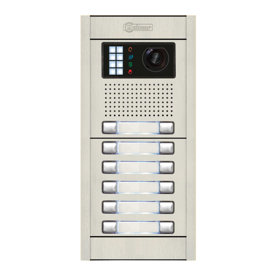
Page 4: Description Of The Nexa Modular Door Panel
NEXA MODULAR G2+ AUDIO AND VIDEO DOOR ENTRY SYSTEM - BUILDING DESCRIPTION OF THE NEXA MODULAR DOOR PANEL Description of the door panel: Door panel component assembly drawing. Electronic Embedding boxes Frame modules Aluminium panel modules Description of the door panel. Fixing screws for clip-on covers (x4) Fixing screws for embedding box (x2) Clip-on... -
Page 5: Description Of The El632 G2 + Se / El642 G2+ Sound Module
Connector (Bus Connection terminals: : Positive, negative (12Vdc output for Golmar DC electric lock). Contact “C” for electric lock (Relay 1). Contact “NO” for electric lock (Relay 1). Input for external door opening button (Relay 1). Input for external door opening button (Relay 1 and Relay 2 Input for external door opening button (Relay ). -
Page 6: Description Of The El610D Button Modules
NEXA MODULAR G2+ AUDIO AND VIDEO DOOR ENTRY SYSTEM - BUILDING DESCRIPTION OF THE EL610D BUTTON MODULE Description of the EL610D button module: Front. Module buttons (x10). Back. Button connector input/output (x3). DIP switch (button call code). Button number. -
Page 7: Positioning The Embedding Box
NEXA MODULAR G2+ AUDIO AND VIDEO DOOR ENTRY SYSTEM - BUILDING INSTALLATION OF THE DOOR PANEL Positioning the embedding box: 1850 1650 1450 Make a hole in the wall to position the top of the door panel at a height of 1.65m. Hole dimensions depend on the type of door panel. -
Page 8: Fitting The Embedding Box
NEXA MODULAR G2+ AUDIO AND VIDEO DOOR ENTRY SYSTEM - BUILDING INSTALLATION OF THE DOOR PANEL Fitting the embedding box: Pass the cable through the hole made in the embedding box. Embed the box and ensure that it is level and flush. Once the embedding box is positioned, remove the protective stickers from the door panel's fixing holes. -
Page 9: Fastening The Frame To The Embedding Box
NEXA MODULAR G2+ AUDIO AND VIDEO DOOR ENTRY SYSTEM - BUILDING INSTALLATION OF THE DOOR PANEL Fastening the frame to the embedding box: Insert the spring hinge which attaches to the product in the embedding box, as shown in the drawing. To fasten the frame to the embedding box, insert the spring hinge into the housings provided for this purpose in the frame, as shown in the drawing. -
Page 10: Connecting The Buttons To The Rap-610D Short Connection Cable
NEXA MODULAR G2+ AUDIO AND VIDEO DOOR ENTRY SYSTEM - BUILDING INSTALLATION OF THE DOOR PANEL Connecting the buttons to the RAP-610D short connection cable: Use the RAP-610D connection cable to connect the buttons between the sound module and the EL610D button module and between EL610D button modules when the distance between modules to be connected is greater due to the composition of the door panels. -
Page 11: Configuring Double Button Module Codes
NEXA MODULAR G2+ AUDIO AND VIDEO DOOR ENTRY SYSTEM - BUILDING INSTALLATION OF THE DOOR PANEL Configuring double button module codes: EL632 G2+ SE Front Back ART 4/G2+ ART 4/G2+ ART 7/G2+ ART 7/G2+ ART 7W/G2+ ART 7W/G2+ Monitor Code Monitor Code Monitor Code C1 NA1 AP+... -
Page 12: Configuring Single Button Module Codes
NEXA MODULAR G2+ AUDIO AND VIDEO DOOR ENTRY SYSTEM - BUILDING INSTALLATION OF THE DOOR PANEL Configuring single button module codes: EL632 G2+ SE Front Back ART 4/G2+ ART 7/G2+ ART 7W/G2+ Monitor Code C1 NA1 AP+ BUSBUS Code 32 Relé... - Page 13 NEXA MODULAR G2+ AUDIO AND VIDEO DOOR ENTRY SYSTEM - BUILDING INSTALLATION OF THE DOOR PANEL Continued from previous page. EL610D Monitor Code Not used Not used Code 20 Code 19 Not used Not used Code 19 Code 18 Not used Not used Code 18 Code 17...
- Page 14 NEXA MODULAR G2+ AUDIO AND VIDEO DOOR ENTRY SYSTEM - BUILDING INSTALLATION OF THE DOOR PANEL Configuring the button code (audio only installation up to 128 te rminals /apartments with EL642 G2+ sound module): The EL610D button module needs to be configured in order to assign a call code to the buttons.
- Page 15 NEXA MODULAR G2+ AUDIO AND VIDEO DOOR ENTRY SYSTEM - BUILDING INSTALLATION OF THE DOOR PANEL Continued from previous page. EL610D button module Single button module codes DIP switch Button code P3 P5 P7 P9 Dip1 Dip2 Dip3 Dip4 Dip5 Dip6 Dip7 Dip8 32 33 34 35 67 68 69 70 P1- P10:...
-
Page 16: Configuring Double Button Module Codes
NEXA MODULAR G2+ AUDIO AND VIDEO DOOR ENTRY SYSTEM - BUILDING INSTALLATION OF THE DOOR PANEL Configuring double button module codes up to 128 terminals/ apartments Front Back EL6 2 G2 ART 1/G2+ ART 1/G2+ T rminal code Terminal code T rminal code Code 27 Code 27... - Page 17 NEXA MODULAR G2+ AUDIO AND VIDEO DOOR ENTRY SYSTEM - BUILDING INSTALLATION OF THE DOOR PANEL Continued from previous page. EL610D T rminal code T rminal code T rminal code Code 40 Code 39 Code 40 Code 37 Code 38 Code 38 Code 36 Code 35...
- Page 18 NEXA MODULAR G2+ AUDIO AND VIDEO DOOR ENTRY SYSTEM - BUILDING INSTALLATION OF THE DOOR PANEL Continued from previous page. EL610D T rminal code T rminal code T rminal code Code 80 Code79 Code 80 Code 80 Code79 Code 78 Code 77 Code 78 Code 78...
- Page 19 NEXA MODULAR G2+ AUDIO AND VIDEO DOOR ENTRY SYSTEM - BUILDING INSTALLATION OF THE DOOR PANEL Continued from previous page. EL610D T rminal code T rminal code T rminal code Code 119 Code 120 Code 120 Code 120 Code 119 Code 117 Code 118 Code 118...
- Page 20 NEXA MODULAR G2+ AUDIO AND VIDEO DOOR ENTRY SYSTEM - BUILDING INSTALLATION OF THE DOOR PANEL Configuring single button module codes up to 7 1 terminals/ apartments EL642 G2+ Front Back ART 1/G2+ T rminal code C1 NA1 AP+ BUSBUS Code 71 Relé...
- Page 21 NEXA MODULAR G2+ AUDIO AND VIDEO DOOR ENTRY SYSTEM - BUILDING INSTALLATION OF THE DOOR PANEL Continued from previous page. EL610D T rminal code Code 20 Not used Not used Code 20 Code 19 Not used Not used Code 19 Code 18 Not used Not used...
- Page 22 NEXA MODULAR G2+ AUDIO AND VIDEO DOOR ENTRY SYSTEM - BUILDING INSTALLATION OF THE DOOR PANEL Continued from previous page. EL610D T rminal code Code 40 Not used Not used Code 40 Code 39 Not used Not used Code. 39 Code 38 Not used Not used...
- Page 23 NEXA MODULAR G2+ AUDIO AND VIDEO DOOR ENTRY SYSTEM - BUILDING INSTALLATION OF THE DOOR PANEL Continued from previous page. EL610D T rminal code Code 60 Not used Not used Code 60 Code 59 Not used Not used Code 59 Code 58 Not used Not used...
-
Page 24: Audio Level Jumper Description (Vocal Synthesis And Tones Mode)
NEXA MODULAR G2+ AUDIO AND VIDEO DOOR ENTRY SYSTEM - BUILDING INSTALLATION OF THE DOOR PANEL Description of the EL632 G2+ SE / EL642 G2+ sound module DIP switch: The DIP switch is located on the left side of the back of the module. Door panel address: Dip switches 1 &... -
Page 25: Description Of The Visual Signals On The Door Panel
NEXA MODULAR G2+ AUDIO AND VIDEO DOOR ENTRY SYSTEM - BUILDING INSTALLATION OF THE DOOR PANEL Description of the visual signals on the door panel (EL632 G2+ SE / EL642 G2+ module): Visual signals on the door panel for people with impaired hearing: While calling: LED will illuminate during in call process. -
Page 26: Description Connector To Digital Converter Cd-Nexa/G2+ / Connection Illumination El3002 Module
NEXA MODULAR G2+ AUDIO AND VIDEO DOOR ENTRY SYSTEM - BUILDING INSTALLATION OF THE DOOR PANEL Description of the connector to CD-NEXA/G2+ digital converter module (EL632 G2+ SE/ EL642 G2+:) The connector to Nexa Bus through the CD-NEXA/G2+ converter , is located t the upper right side of the back of the sound module. -
Page 27: Selecting Vocal Synthesis Language Or Tones Mode
NEXA MODULAR G2+ AUDIO AND VIDEO DOOR ENTRY SYSTEM - BUILDING INSTALLATION OF THE DOOR PANEL Selecting vocal synthesis language or tones mode (EL632 G2+ SE / EL642 G2+ module) The configuration D switch is located on the left side of the back of the module. If you want to change the language of the vocal synthesis or select the tones mode of the door panel, configure dips 4 to 8 of the configuration Dip switch (page 24), see the following selection table:... - Page 28 NEXA MODULAR G2+ AUDIO AND VIDEO DOOR ENTRY SYSTEM - BUILDING INSTALLATION OF THE DOOR PANEL Change the call code of the P1 and P2 button of the EL632 G2+ SE / EL642 G2+ module: If you want to change the call code of button P1 of the sound module, follow these steps: (Factory value P1 = 32).
-
Page 29: Closing The Frame And I Nserting The Button Identification Labels
NEXA MODULAR G2+ AUDIO AND VIDEO DOOR ENTRY SYSTEM - BUILDING INSTALLATION OF THE DOOR PANEL Closing the frame: Once the wiring and configuration work is done, fix the frame to the embedding box using the screws supplied. Important: Before closing the door panel(s) make a test call to any apartment to ensure that everything works correctly. - Page 30 NEXA MODULAR G2+ AUDIO AND VIDEO DOOR ENTRY SYSTEM - BUILDING INSTALLATION OF THE DOOR PANEL Mounting the modules of a door panel: Insert a clip-on cover into the side profiles (from the bottom) and fix it using the screws specified (step 1 ) and then insert the module (step 2 ).
- Page 31 NEXA MODULAR G2+ AUDIO AND VIDEO DOOR ENTRY SYSTEM - BUILDING INSTALLATION OF THE DOOR PANEL Mounting the modules of a double door panel: Mount door panel A (step 1 ) as described in 'Mounting the modules of a door panel' (see page ), taking into account that the bar connecting panel A and panel B must be a door panel UNE rod, see drawing below.
-
Page 32: Installing The Lock Release Installation
For wooden doors, use a Ø3mm drill bit. M 4 x 8 DIN-963 IMPORTANT: The lock release must be 12V DC or AC (Golmar). (See pages 49 and 52 for a.c. lock release and page . 34-45 and 49-52 for d.c lock release... -
Page 33: Installing The Power Supply Unit (Fa-G2 )
± MADE IN CHINA BUS 30V 2V 1. A BUS BUS GOLMAR S.A. C/ Silici, 13 08940 - SPAIN A. On/off indicator light. B. Protective cover for the current input. C. Detail of current input terminals without protective BUS(M) BUS PL cover. - Page 34 NEXA MODULAR G2+ AUDIO AND VIDEO DOOR ENTRY SYSTEM - BUILDING WIRING DIAGRAMS Audio door entry system with 128 apartments / ART 1/G2+ terminals Golmar d.c lock release ART 1/G2+ ART 1/G2+ Master Master Make the connections in electrical junction box.
- Page 35 BUILDING 1 RISER 1 RISER 2 RISER 3 RISER 4 RISER 5 RISER 6 RISER 7 RISER 8 Distances and cross-sections: Riser 1 Riser 2 ART /G2+ ART /G2+ Riser 3 Riser 4 Riser 5 Cable Riser 6 RAP-GTWIN/HF 2x1mm 80m 50m 45m ART /G2+ ART /G2+...
- Page 36 NEXA MODULAR G2+ AUDIO AND VIDEO DOOR ENTRY SYSTEM - BUILDING WIRING DIAGRAMS Video door entry system with 3 2 ART 4 /G2+ or ART 4 LITE/G2+ monitors, 8 D4L- 2+ distribu tors and Golmar d.c lock release. ART 4/G2+ ART 4/G2+ Master Master End of ( ) 2 (...
- Page 37 WIRING DIAGRAMS Video door entry system with 3 2 ART 4/G2+ or ART 4 LITE/G2+ monitors, 16 2 G D L- 2+ distribu tors and Golmar d.c lock release ART 4/G2+ ART 4/G2+ Master Master End of l ne APARTMENT 31...
- Page 38 NEXA MODULAR G2+ AUDIO AND VIDEO DOOR ENTRY SYSTEM - BUILDING WIRING DIAGRAMS Mixed installation: Up to 32 elements (ART 4/G2+ or ART 4 LITE/G2+ monitors / ART 1/G2+ audio terminals), 8 D4L-G2+ distributors and Golmar d.c lock release Additional ART 1/G2+ terminal (in the same apartment)
- Page 39 NEXA MODULAR G2+ AUDIO AND VIDEO DOOR ENTRY SYSTEM - BUILDING WIRING DIAGRAMS Video door entry system with 3 2 ART /G2+ or ART 7LITE/G2+ monitors, 8 D4L- 2+ distribu tors and Golmar d.c lock release ART 7/G2+ ART 7/G2+ Master Master End of...
- Page 40 WIRING DIAGRAMS Video door entry system with 3 2 ART /G2+ or ART7 LITE/G2+ monitors, 16 2 G D L- 2+ distribu tors and Golmar d.c lock release ART 7/G2+ ART 7/G2+ Master Master End of l ne APARTMENT 31...
- Page 41 NEXA MODULAR G2+ AUDIO AND VIDEO DOOR ENTRY SYSTEM - BUILDING WIRING DIAGRAMS Mixed installation: Up to 32 elements (ART 7/G2+ or ART 7 LITE/G2+ monitors / ART 1/G2+ audio terminals), 8 D4L-G2+ distributors and Golmar d.c lock release Additional ART 1/G2+ terminal in the same apartment...
- Page 42 NEXA MODULAR G2+ AUDIO AND VIDEO DOOR ENTRY SYSTEM - BUILDING WIRING DIAGRAMS Video door entry system with 3 2 ART /G2+ monitors, 8 D4L- 2+ distribu tors and Golmar d.c lock release ART 7W/G2+ ART 7W/G2+ Master Master FA-ART 7W FA-ART 7W...
- Page 43 WIRING DIAGRAMS Video door entry system with 3 2 ART /G2+ monitors, 16 2 G D L- 2+ distribu tors and Golmar d.c lock release ART 7W/G2+ ART 7W/G2+ Master Master FA-ART 7W FA-ART 7W ( ) 2 ( ( ) 2 (...
- Page 44 NEXA MODULAR G2+ AUDIO AND VIDEO DOOR ENTRY SYSTEM - BUILDING WIRING DIAGRAMS Mixed installation: Up to 32 elements (ART 7 W/G2+ monitors / ART 1/G2+ audio terminals), 8 D4L-G2+ distributors and Golmar d.c lock release Additional ART 1/G2+ terminal in the same apartment...
- Page 45 NEXA MODULAR G2+ AUDIO AND VIDEO DOOR ENTRY SYSTEM - BUILDING WIRING DIAGRAMS Video door entry system with monitors 7/G2+ or ART 7 LITE/G2+ monitors IN-OUT without distribui tors & Golmar d.c lock release ART 7/G2+ Master APARTMENT 12 ART 7/G2+ Master APARTMENT 4 ART 7/G2+ Master...
- Page 46 To "Bus M" of the FA-G2+ power supply (see page 49 . Note: If more than 1 access door panel (see page 50-51).
- Page 47 To "Bus M" of the FA-G2+ power supply (see page 49 . Note: If more than 1 access door panel (see page 50-51).
- Page 48 BUILDING 1 RISER 1 RISER 2 RISER 3 RISER 4 ART 7/G2+ ART 7/G2+ ART 7/G2+ ART 7/G2+ Master Master Master Master APARTMENT 8 APARTMENT 16 APARTMENT 24 APARTMENT 32 ART 7/G2+ ART 7/G2+ ART 7/G2+ ART 7/G2+ Master Master Master Master APARTMENT 2...
- Page 49 (from 2 to 4) and 1 door panel with Golmar d.c lock release. 1 Building of audio door entry system with risers (from 1 to 8) and 1 door panel with Golmar d.c lock release. Video door entry system: To...
- Page 50 100~240Vac FA-G2+ BUS (M) BUS(PL) Max. distance: 1m. DPM- 2+ IMPORTANT: Installations of 1 or 2 access door panels (Golmar d.c lock release): Max. 2 external door opening button 'AP'. 1 'AP' button installed in each door panel. Access door panel 1...
- Page 51 Mains 100~240Vac FA-G2+ BUS (M) BUS(PL) Max. distance: 1m. DPM- 2+ IMPORTANT: Installations of more than 2 access door panels (Golmar d.c lock release): Max. 1 external door opening button 'AP'. 1 'AP' button installed in only one of the door panels of the installation.
-
Page 52: Wiring Diagrams
Relé 2 12Vdc AP1 AP2 Lock release max. 12 Vdc/270mA. Important: Installation with 1 acces door panel and 2 Golmar d.c lock release (see note "IMPORTANT" of maximum of AP´s in page. nection of a.c lock release with "AP": Access door panel... -
Page 53: Installation Riser Types
NEXA MODULAR G2+ AUDIO AND VIDEO DOOR ENTRY SYSTEM - BUILDING T P S Y E OF RISER INSTALLATION Installation with 1 building, 32 monitors, 2 risers and 1 access door panel. BUILDING 1 RISER 1 RISER 2 ART 4/ ART 4/ ART 4/ ART 4/... - Page 54 BUILDING 1 RISER 1 RISER 2 RISER 3 RISER 4 ART 4/ ART 4/ ART 4/ ART 4/ ART 4/ ART 4/ ART 4/ ART 4/ ART 7/ ART 7/ ART 7/ ART 7/ ART 7/ ART 7/ ART 7/ ART 7/ ART 7W/ ART 7W/...
- Page 55 Installation with 1 building, 32 monitors, 4 asymmetric risers and 1 access door panel. BUILDING 1 RISER 1 RISER 2 RISER 3 RISER 4 ART 4/ ART 4/ ART 4/ ART 4/ ART 4/ ART 4/ ART 4/ ART 4/ ART 7/ ART 7/ ART 7/...
- Page 56 BUILDING 1 RISER 1 RISER 2 RISER 3 RISER 4 ART 4/ ART 4/ ART 4/ ART 4/ ART 4/ ART 4/ ART 4/ ART 7/ ART 7/ ART 7/ ART 7/ ART 7/ ART 7/ ART 7/ ART 7W/ ART 7W/ ART 7W/ ART 7W/...
- Page 57 BUILDING 1 RISER 1 RISER 2 RISER 3 RISER 4 ART 4/ ART 4/ ART 4/ ART 4/ ART 7/ ART 7/ ART 7/ ART 7/ ART 7W/ ART 7W/ ART 7W/ ART 7W/ Apartment 8 Apartment 16 Apartment 24 Apartment 32 Apartment 11 Apartment 19...
-
Page 58: Con E N Ction Of An External Camera
NEXA MODULAR G2+ AUDIO AND VIDEO DOOR ENTRY SYSTEM - BUILDING CONNECTION OF AN EXTERNAL CAMERA It is possible to connect a Golmar AHD4-3601x analogue CCTV to the door panel, which can be viewed from the monitor, see corresponding monitor to activate the external camera CCTV i n "... -
Page 59: Not S
NEXA MODULAR G2+ AUDIO AND VIDEO DOOR ENTRY SYSTEM - BUILDING NOT S... -
Page 60: Compliance
C/ Silici, 13 08940- Cornellá de Llobregat SPAIN Golmar se reserva el derecho a cualquier modificación sin previo aviso. Golmar se réserve le droit de toute modification sans préavis. Golmar reserves the right to make any modifications without prior notice.
Need help?
Do you have a question about the Nexa Modular G2+ and is the answer not in the manual?
Questions and answers