golmar DQ-IPCAM G2+ Instruction Manual
Ip cameras unit
Hide thumbs
Also See for DQ-IPCAM G2+:
- User manual (60 pages) ,
- Instruction manual (26 pages) ,
- Quick manual (9 pages)
Table of Contents
Advertisement
Quick Links
Advertisement
Table of Contents

Related Manuals for golmar DQ-IPCAM G2+


Summary of Contents for golmar DQ-IPCAM G2+
- Page 1 TECHNOLOGY DQ-IPCAM G2+ IP CAMERAS UNIT Adapter DC 12V 1A HDMI GOLMAR S.A. RJ45 C/ Silici, 13 12458990 V01 08940-SPAIN CAMERA UNIT DQ-IPCAM-G2+ LED1 LED2 RESET DIP SWITCH Mode Switch Micro SD Card slot Code 50123134 TDQ-IPCAM G2+ EN REV.0221...
-
Page 2: Table Of Contents
- Use the Golmar RAP-GTWIN/HF cable (2x1mm ) in installation of video door entry system. - Use the Golmar UTP-5E305 (RJ-45) cable for connection of the DQ-IPCAM G2+ IP camera unit to the switch and connection of the IP cameras. -
Page 3: Safety Precautions
DQ-IPCAM G2+ IP CAMERAS UNIT SAFETY PRECAUTIONS - Always disconnect the power supply before installing or making modifications to the device. - The fitting and handling of this device must be carried out by authorised personnel. - The wiring must run at list 40 cm. de cualquier otra instalación. - Install the DQ-IPCAM G2+ unit in a dry protected location free from risk of dripping or splashing water. -
Page 4: Dq-Ipcam G2+ Unit Instaled In Monitor Bus
Cable B+ + RAP-GTWIN/HF 2x1mm 80m 80m 80m 190m (Distances with Golmar RAP-2150 cable (twisted pair 2x1mm ). IMPORTANT: - For more information see characteristics, page 3. - For description, installation, configuration and programming of door panels and monitors, see the corresponding manuals. -
Page 5: Dq-Ipcam G2+ Unit Instaled In Door Panel Bus
Cable B+ + RAP-GTWIN/HF 2x1mm 80m 80m 80m 190m (Distances with Golmar RAP-2150 cable (twisted pair 2x1mm ). IMPORTANT: - For more information see characteristics, page 3. - For description, installation, configuration and programming of door panels and monitors, see the corresponding manuals. -
Page 6: Dq-Ipcam G2+ Unit Instaled In Inner Door Panel Bus & General Door Panel Bus
DQ-IPCAM G2+ IP CAMERAS UNIT INSTALLATION MODES OF THE DQ-IPCAM G2 + CAMERA UNIT... -
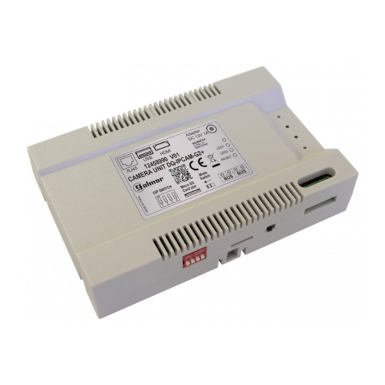
Page 7: Description Of The Dq-Ipcam G2+ Ip Cameras Unit
DQ-IPCAM G2+ IP CAMERAS UNIT DESCRIPTION OF THE DQ-IPCAM G2+ IP CAMERAS UNIT Description: FRONT Adapter DC 12V 1A HDMI GOLMAR S.A. RJ45 C/ Silici, 13 12458990 V01 08940-SPAIN CAMERA UNIT DQ-IPCAM-G2+ LED1 LED2 RESET Mode DIP SWITCH BOTTOM Switch... -
Page 8: Setting Ip Addresses Of The Ip Cameras
Note: The detailed software is the “ Device Config Tool ” to configure the addresses of the Golmar IP cameras. Connect a UTP RJ45 cable to a computer (with the "Device Config tool" software installed, see mini CD enclosed with the IP camera) and the other end of the cable connect it to the switch (the picture below is a switch with ports PoE and a Golmar IP/PoE camera). - Page 9 DQ-IPCAM G2+ IP CAMERAS UNIT Continued from previous page. INSTALLATION Setting the IP address(es) of the IP camera(s): Click on the IP camera line to edit. Change the IP address of the camera and make sure that the network segment of the IP camera is the same as the DQ-IPCAM G2+ unit (see page 11).
- Page 10 DQ-IPCAM G2+ IP CAMERAS UNIT Continued from previous page. INSTALLATION Setting the IP address(es) of the IP camera(s): The new IP camera address will then be displayed. 192.168.1.2 Important: -If there is more than one IP camera installed in the building, it must be connected and configured one by one to the switch to change the IP address of the camera.
-
Page 11: Setting Of Dq-Ipcam G2+ Ip Cameras Unit (Local Mode)
Micro SD Switch Main Card slot 100~240Vca Golmar IP/PoE Camera FA-G2+ BUS (M) BUS (PL) To monitors To door panel Connect the DQ-IPCAM unit to the display with an HDMI cable and turn on the display. To access the main menu click on the right mouse button and select the "Main menu"... - Page 12 DQ-IPCAM G2+ IP CAMERAS UNIT Continued from previous page. INSTALLATION Access Channel -- IP Channel. Click on the "Search" option, the connected IP cameras will be displayed. Then click on the IP camera to be configured. Important: The IP addresses of the IP cameras must be configured (see pages 8-10). ONVIF 192.168.1.2 Search...
- Page 13 DQ-IPCAM G2+ IP CAMERAS UNIT Continued from previous page. INSTALLATION The IP camera is already linked and connected. To view the IP camera image, click the right mouse button (see page 14). 192.168.1.2 ONVIF ONVIF 192.168.1.2 Click on System--General to configure parameters of date/time, language, etc..., click on the "Apply" option to confirm.
- Page 14 DQ-IPCAM G2+ IP CAMERAS UNIT Continued from previous page. INSTALLATION Press the right mouse button to select the display mode of the installed IP cameras.
-
Page 15: Setting Of Dq-Ipcam G2+ Ip Cameras Unit (Web Browser)
Setting of DQ-IPCAM G2+ unit: (Web browser mode) It also allows setting by a web browser (Firefox, Chrome, Explorer...). In installations with a PoE Switch and Golmar IP/PoE cameras, connect the computer to an UP-LINK port, as shown below: PORTS... - Page 16 DQ-IPCAM G2+ IP CAMERAS UNIT Continued from previous page. INSTALLATION Step 2: Click on the "Change adapter options". Step 3: Click twice on the active Ethernet connection. 1 elemento Continued overleaf...
- Page 17 DQ-IPCAM G2+ IP CAMERAS UNIT Continued from previous page. INSTALLATION Step 4: In the Ethernet status window, click on the "properties". 1 item Step 5: In the Ethernet properties window, Click twice and access the "Internet Protocol version 4 (TCP/IPv4)". 1 item Continued overleaf...
- Page 18 DQ-IPCAM G2+ IP CAMERAS UNIT Continued from previous page. INSTALLATION Step 6: Set the IP range in the "Internet Protocol version 4 (TCP/IPv4) Properties" window, with the same IP range of the DQ-IPCAM unit (default "192.168.1.200"). Internet protocol version 4 (TCP&IPv4) Properties Change IP address e.g: “192.168.1.250"...
- Page 19 DQ-IPCAM G2+ IP CAMERAS UNIT Continued from previous page. INSTALLATION To access the IP address of the DQ-IPCAM G2+ unit, click on Set--Network--IP address; and edit/change the IP address (if there is more than one unit) of the DQ-IPCAM G2+ unit (default value: 192.168.1.200). It is necessary to modify the IP address of the DQ-IPCAM unit (default: 192.168.1.200) if there is more than one DQ- IPCAM unit (installation of general boards and indoor buildings).
- Page 20 DQ-IPCAM G2+ IP CAMERAS UNIT Continued from previous page. INSTALLATION Access Channel--Digital Channel. Click on the "Search" option, the connected IP cameras will be displayed. Important: The IP addresses of the IP cameras must be configured (see pages 8-10). 192.168.1.2 Select the "Channel"...
- Page 21 DQ-IPCAM G2+ IP CAMERAS UNIT Continued from previous page. INSTALLATION Click on the "Edit" option and select the "Password" field, enter the camera password (admin) and click on the "OK" option to confirm. admin The IP camera is already linked and connected. Connected (1080P/VGA) To view the IP camera image, click on Preview--CAM1 Network.
-
Page 22: Setting The Button Code (Up To 32 Addresses/Apartments)
Note: EL632 G2+ SE module V04 & later, P1 and P2 push buttons must be changed the call code (for example "32" in P1 and "31" in P2), see manual: https://doc.golmar.es/search/manual/50122528 (page 28). Important: Select a different configuration option for each EL610D module. - Page 23 DQ-IPCAM G2+ IP CAMERAS UNIT INSTALLATION Configuring double button module codes: EL632 G2+ SE Front Back ART 7W/G2+ ART 7W/G2+ Monitor Code Monitor Code Monitor Code C1 NA1 AP+ BUSBUS Relé 1 Relé 2 Code 32 Code 31 Code 31 12Vdc Code 31 Cod.
- Page 24 DQ-IPCAM G2+ IP CAMERAS UNIT INSTALLATION Configuring single button module codes: EL632 G2+ SE Front Back ART 7W/G2+ Monitor Code C1 NA1 AP+ BUSBUS Code 32 Relé 1 Relé 2 12Vdc Not used Not used Cod. 32 EL610D Code 5 Not used Cod.
- Page 25 DQ-IPCAM G2+ IP CAMERAS UNIT Continued from previous page. INSTALLATION EL610D Cod. Monitor Code 20 Not used Not used Cod. 20 Code 19 Not used Not used Cod. 19 Code 18 Not used Not used Cod. 18 Code 17 Not used Not used Cod.
-
Page 26: Wiring Diagrams
DQ-IPCAM G2+ IP CAMERAS UNIT WIRING DIAGRAMS Video door entry system in building with DQ-IPCAM ( installed in monitor bus ART 7W/G2+ ART 7W/G2+ FA-ART 7W Master FA-ART 7W Master (2) ( (2) ( APARTMENT 31 APARTMENT 32 End of line 24V GND BUS BUS... -
Page 27: Installation Of Video Door Entry System With Dq-Ipcam G2+ Unit Installed In Door Panel Bus
DQ-IPCAM G2+ IP CAMERAS UNIT WIRING DIAGRAMS Video door entry system in building with DQ-IPCAM ( installed in door panel bus ART 7W/G2+ ART 7W/G2+ FA-ART 7W Master FA-ART 7W Master (2) ( (2) ( APARTMENT 31 APARTMENT 32 End of line 24V GND BUS BUS... -
Page 28: Installation Of Video Door Entry System With Dq-Ipcam G2+ Unit Installed In Inner Door Panel & General Door Panel Bus
DQ-IPCAM G2+ IP CAMERAS UNIT WIRING DIAGRAMS... -
Page 29: Installation Of Video Door Entry System With 1 Access Panel
DQ-IPCAM G2+ IP CAMERAS UNIT WIRING DIAGRAMS Video door entry system with 1 access door panel and Golmar DC lock release (DQ-IPCAM G2+ unit installed in monitor bus, see page 4). To first (RD-G2+ N° 1) of the building/installation (see page 28). -
Page 30: Installation Of Video Door Entry System With Dq-Ipcam G2+ Unit And 2 Access Panel
DQ-IPCAM Note: DQ-IPCAM unit, counts as one door panel. IMPORTANT: Installations with 1 or 2 door panels (Golmar DC lock release): Max. 2 external door opening button 'AP'. 1 'AP' button installed in each door panel. Access panel 1 Access panel 2... -
Page 31: Installation Of Video Door Entry System With Dq-Ipcam G2+ Unit And 3 Access Panel
FA-G2+ BUS (M) BUS (PL) Max. distance 1m. IMPORTANT: Installations of more than 2 access door panels (Golmar d.c lock release): DPM-G2+ Max. 1 external door opening button 'AP'. 1 'AP' button installed in only one of the door panels of the installation. -
Page 32: Connection Of Golmar Dc An Ac Lock Releases. Golmar
AP1 AP2 Lock release max. 12 Vdc/270mA. Important: Installation with 1 access door panel and 2 Golmar d.c lock release (see note "IMPORTANT" of maximum of AP´s in page 30). Connection of 1 a.c lock release with “AP": Access panel... -
Page 33: Special Code & Operation Of The Ip Camera Preview Menu (Only Art 7W/G2+ Monitor With V.08 And Later)
ART 7W/G2+ MONITOR SPECIAL CODES To display the IP cameras of the DQ-IPCAM unit on the ART 7W/G2+ monitor (with V.08 and later), it is necessary to enter the special code "0581". To do this, the installer menu must be accessed from the monitor. Go to the "About"... - Page 34 ART 7W/G2+ MONITOR OPERATION OF THE IP CAMERA PREVIEW MENU Viewing the IP cameras of the DQ-IPCAM/G2+ unit: Once the apartment monitor(s) with the special code "0581" is activated (see page 33), the apartment monitor(s) will display the icon in the main menu of the monitor. Remember: Only ART 7W/G2+ monitor (with V.08 and later).
- Page 35 ART 7W/G2+ MONITOR Continued from previous page. OPERATION OF THE IP CAMERA PREVIEW MENU If you click on the icon of an IP camera, for example , you will see the image of IP camera 1. If you click on the icon you will see the images on the same screen of the cameras IP1 to IP4 installed.
-
Page 36: Compliance
C/ Silici, 13 08940- Cornellá de Llobregat SPAIN Golmar se reserva el derecho a cualquier modificación sin previo aviso. Golmar se réserve le droit de toute modification sans préavis. Golmar reserves the right to make any modifications without prior notice.
Need help?
Do you have a question about the DQ-IPCAM G2+ and is the answer not in the manual?
Questions and answers