golmar Soul kit User Manual
2-wire installation video door entry system kit
Hide thumbs
Also See for Soul kit:
- Quick manual (8 pages) ,
- Quick manual (4 pages) ,
- Quick manual (4 pages)

Subscribe to Our Youtube Channel
Related Manuals for golmar Soul kit


Summary of Contents for golmar Soul kit
- Page 1 Soul kit TECHNOLOGY G2+ 2-wire installation Art 7 monitor Code 50122125 TS5110 ART 7 EN REV.0319...
-
Page 2: Table Of Contents
SOUL S5110/ART 7 VIDEO DOOR ENTRY SYSTEM KIT CONTENTS Contents ..................................2 Recommendations..............................3 System operation ...............................3 Optional ..................................3 FA-G2+ power supply..............................4 Descrip tion ..............................4 Installation ...............................4 Soul panel................................5 to 8 Descrip tion ..............................5 Installation ...............................6 Installation terminals ............................6 Configuration switches.............................7 Setting the audio level ............................7 Programming the proximity reader ........................8 Art 7/G2+ monitor...............................9 to 24 Description ..............................9... -
Page 3: Recommendations
SOU S5110/ART 7 VIDE O DOOR RY SYSTEM KIT RECOMMENDATIONS - Preferably use a Golmar RAP-GTWIN/HF cable (2x1mm²). - The wiring must run at least 40cm away from any other wiring. - Always disconnect the power supply before making modifications to the device. -
Page 4: Fa-G2+ Power Supply
OUTPUT MADE IN CHINA BUS 30V 2V 1.2A ± BUS BUS GOLMAR S.A. C/ Silici, 13 08940 - SPAIN A. On/off indicator light. B. Protective current input cover. C. Detail of current input terminals without protective BUS(M) BUS PL cover. -
Page 5: Soul Panel
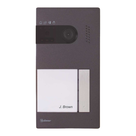
SOU S5110/ART 7 VIDE O DOOR RY SYSTEM KIT SOUL PANEL Description A. System status icons: Call in progress. Communication established. Lock release activated. System busy. B. System status indicator lights. C. Ambient lighting sensor. D. Night viewing lighting. E. Protective polycarbonate. F. -
Page 6: Installation
SOU S5110/ART 7 VIDE O DOOR RY SYSTEM KIT SOUL PANEL Installation The door panel has been designed to withstand diverse environmental conditions. It is however advisable to take extra precautions to prolong its service life, such as locating it in a covered area. For optimum image quality, avoid direct contact from light sources (sunshine, street lights, etc.). -
Page 7: Configuration Switches
SOU S5110/ART 7 VIDE O DOOR RY SYSTEM KIT SOUL ANEL Configuration switches (R) Configuration changes should be made with the equipment turned off. If they are performed with the equipment turned on, disconnect it for 10 seconds after any modification. All switches are factory set to OFF. -
Page 8: Programming The Proximity Reader
SOU S5110/ART 7 VIDE O DOOR RY SYSTEM KIT SOUL ANEL Programming the proximity reader (L) Make sure that the device is powered and the reader is connected to the door panel (Q). To add user keys (up to 60) to the memory of the proximity reader, it is necessary to create a programming key and a user registration key. -
Page 9: Art 7/G2+ Monitor
7/G2+ MONITOR Description Hidden button pressing area 12210701 Product Version: MONITOR 7” ART 7/G2+ GOLMAR S.A. CAUTION C/ Silici, 13 TO PREVENT ELECTRIC SHOCK, 08940 - SPAIN WARNING DO NOT REMOVE COVER. NO TO PREVENT FIRE OR ELECTRIC USER SERVICEABLE PARTS SHOCK, DO NOT EXPOSE THIS INSIDE. -
Page 10: Installation
SOU S5110/ART 7 VIDE O DOOR RY SYSTEM KIT ART 7/G + M ONITOR Installation Avoid dusty or smoky environments or locations near sources of heat. For proper installation, use the template supplied with the product. 1. Position the top of the template at a height of 1.65m. 2. -
Page 11: Main Menu
SOU S5110/ART 7 VIDE O DOOR RY SYSTEM KIT MONITOR ART 7/G2+ Main menu 01 7 -0 -201 09:27 LED indicators Hidden button pressing area Raised dots for the visually impaired If the device is in standby (screen switched off), to access the main menu, press either of the 2 hidden buttons with indicator LEDs illuminated (located above the raised dots for the visually impaired) on the monitor. - Page 12 SOU S5110/ART 7 VIDE O DOOR RY SYSTEM KIT 7/G2+ MONITOR Settings menu Returning to the main menu: Press the hidden button below icon to return to the main menu. Setting the monitor's date and time, as well as the presentation format: Press the hidden button below icon to access the settings screen.
- Page 13 SOU S5110/ART 7 VIDE O DOOR RY SYSTEM KIT Continued from previous page. 7/G2+ MONITOR Settings menu elect the field to modify by pressing the hidden buttons below corresponding icons , then press the hidden buttons below corresponding icons to adjust the value/format. Validate the changes made by pressing the hidden button with icon .
- Page 14 SOU S5110/ART 7 VIDE O DOOR RY SYSTEM KIT 7/G2+ MONITOR Settings menu Automatically deleting images/videos, image recording mode, internal memory and Micro SD card: Press the hidden button below icon to access the settings screen. In some countries, the law does not permit the storage of images or videos for more than 30 days after recording.
- Page 15 SOU S5110/ART 7 VIDE O DOOR RY SYSTEM KIT Continued from previous page. 7/G2+ MONITOR Settings menu If you have inserted a Micro SD card into the monitor, you can delete the still images and videos recorded on the Micro SD card. The monitor has the option to format the Micro SD card. Press the hidden button below icon to return to the settings menu.
-
Page 16: Settings Menu
SOU S5110/ART 7 VIDE O DOOR RY SYSTEM KIT Continued from previous page. 7/G2+ MONITOR Settings menu To activate and set a period of time for the automatic opening of door (after 3 seconds of receiving a call from the door panel), go to the option with icon by pressing the hidden buttons below corresponding icons and select the automatic door opening function... -
Page 17: Door Panel Call Screen
SOU S5110/ART 7 VIDE O DOOR RY SYSTEM KIT 7/G2+ MONITOR Door panel call screen 0 -0 -2 1 7 019 11:17:10 This screen is displayed when you receive a call or when you press the hidden button below icon of the main menu. -
Page 18: Communication Screen
SOU S5110/ART 7 VIDE O DOOR RY SYSTEM KIT 7/G2+ MONITOR Communication screen 0 -0 -2 1 7 019 11:17:10 This screen is displayed during a communication process. In the top centre of the screen, the date and time are shown and, on the right, the source of the image is displayed (door panel 1, door panel 2, camera 1 or camera 2). -
Page 19: Image And Communication Settings
SOU S5110/ART 7 VIDE O DOOR RY SYSTEM KIT 7/G2+ MONITOR Image and communication settings During a communication process, press the hidden button below icon to access the image and monitor in communication volume settings menu 0 -0 -2 1 7 019 11:17:10 The following settings menu will then appear (brightness, contrast, colour and monitor in communication volume). - Page 20 SOU S5110/ART 7 VIDE O DOOR RY SYSTEM KIT 7/G2+ MONITOR Intercom menu ccess the intercom menu as described on p. 11. From this menu, you can contact another monitor(s) in your apartment (internal intercom) or other apartments (external intercom). For external intercom, the monitor called must have its intercom function enabled from the 'Do not disturb' menu (factory setting: disa bled)
-
Page 21: Intercom Menu
SOU S5110/ART 7 VIDE O DOOR RY SYSTEM KIT Continued from previous page. 7/G2+ MONITOR Intercom menu To make an external intercom call (to another monitor(s) in the same apartment), go to the option with icon by pressing the hidden buttons below corresponding icons and press the hidden button below icon to access the code selection menu of the apartment with which you wish to communicate. - Page 22 SOU S5110/ART 7 VIDE O DOOR RY SYSTEM KIT ART 7/G2+ MONITOR Recordings menu ccess the recordings menu as described on p. 11. This menu displays the list of images saved in the memory of the device. If a Micro SD card is inserted in the monitor, images/videos will be recorded on the Micro SD card. Press the hidden button below icon to access the list of videos saved on the Micro SD card.
- Page 23 SOU S5110/ART 7 VIDE O DOOR RY SYSTEM KIT Continued from previous page. MONITOR ART 7/G2+ Recordings menu If a Micro SD card is inserted in the monitor, press the hidden button below icon to access the list of videos. In the list of recorded videos, those that have not been viewed are highlighted in white.
-
Page 24: Recordings Menu
SOU S5110/ART 7 VIDE O DOOR RY SYSTEM KIT Continued from previous page. 7/G2+ MONITOR Recordings menu To return to the main menu, press the hidden button below icon 01 / 03 0 -0 -2 9 7 019 8 21 0 -0 -2 9 7 019 1 :17: 0... -
Page 25: Wiring Diagrams
SOU S5110/ART 7 VIDE O DOOR RY SYSTEM KIT WIRING DIAGRAMS Cross sections and distances The maximum number of monitors per apartment is 4 - The maximum number of monitors in cascade is 12. ART 7/G2+ ART 7/G2+ ype of cable 2 x 0 75mm²... -
Page 26: One Apartment With Up To Two Access Panels And Up To Four Monitors In Cascade
SOU S5110/ART 7 VIDE O DOOR RY SYSTEM KIT WIRING DIAGRAMS One apartment with up to two access panels and up to four monitors in cascade Mains 100~240V a SOUL/1 SOUL/1 ART 7/G2+ ART 7/G2+ ART 7/G2+ DOOR PANEL 2 DOOR PANEL 1 APARTMENT APARTMENT 1... -
Page 27: Two Apartments With Up To Two Access Panels And Up To Four Monitors In Cascade
SOU S5110/ART 7 VIDE O DOOR RY SYSTEM KIT WIRING DIAGRAMS Two apartments with up to two access panels and up to four monitors in cascade ART 7/G2+ ART 7/G2+ ART 7/G2+ ART 7/G2+ APARTMENT 2 APARTMENT 2 APARTMENT 2 APARTMENT 2 SLAVE MONITOR 3... -
Page 28: Four Apartments With Up To Two Access Panels And Up To Four Monitors In Cascade
SOU S5110/ART 7 VIDE O DOOR RY SYSTEM KIT WIRING DIAGRAMS Four apartments with up to two access panels and up to four monitors in cascade ART 7/G2+ ART 7/G2+ ART 7/G2+ ART 7/G2+ APARTMENT APARTMENT APARTMENT APARTMENT SLAVE MONITOR SLAVE MONITOR 2 SLAVE... -
Page 29: Four Apartments With Up To Four Access Panels And Up To Four Monitors In Cascade
SOU S5110/ART 7 VIDE O DOOR RY SYSTEM KIT WIRING DIAGRAMS Four apartments with up to four access panels and up to four monitors in cascade ART 7/G2+ ART 7/G2+ ART 7/G2+ ART 7/G2+ APARTMENT APARTMENT APARTMENT APARTMENT SLAVE MONITOR SLAVE MONITOR 2 SLAVE... -
Page 30: Connection Of A Lock Release
CV+ AP+ If the lock release to be used is alternating current, use a relay and transformer suitable for the consumption, as well as the varistor supplied. The example shows a Golmar SAR-12/24 relay and a TF-104 transformer (12Vac / 1.5A) -
Page 31: Connection Of An Exit Button
Connection of an external camera It is possible to connect a Golmar AHD4-3601x analogue CCTV camera to each of the door panels, which can be viewed (see pp. 32-34) from the monitor. The camera needs to have a local PSU-121 power supply... -
Page 32: Special Codes
SOU S5110/ART 7 VIDE O DOOR RY SYSTEM KIT SPECIAL CODES The enabling of some functions, as well as the modification of some factory parameters, can be carried out by entering special codes. To do so, the installer menu must be accessed from the monitor. Go to the 'About' screen in the Settings menu (p. - Page 33 SOU S5110/ART 7 VIDE O DOOR RY SYSTEM KIT Continued from previous page. SPECIAL CODES Video sources available on a monitor (configure only on master monitor) Visible Not Visible Factory setting Door panel 1 0111 0110 0111 Door panel 2 0121 0120 0120...
- Page 34 SOU S5110/ART 7 VIDE O DOOR RY SYSTEM KIT Continued from previous page. SPECIAL CODES Activation times of the outputs (Door panel ). 3 (Only setting on master monitor). Factory setting Lock release From 200 (0.5s) to 219 (10s) 20 (3s) Relay From 300 (0.5s) to 319 (10s) 30 (3s)
-
Page 35: Cleaning The Monitor
SOU S5110/ART 7 VIDE O DOOR RY SYSTEM KIT CLEANING THE MONITOR - Do not use solvents, detergents or cleaning products that contain acids, vinegar or abrasive components. - Use a soft, damp cloth (not wet) that does leave lint behind. - Always wipe the monitor in the same direction, from top to bottom. -
Page 36: Compliance
C/ Silici, 13 08940- Cornellá de Llobregat SPAIN Golmar se reserva el derecho a cualquier modificación sin previo aviso. Golmar se réserve le droit de toute modification sans préavis. Golmar reserves the right to make any modifications without prior notice.
Need help?
Do you have a question about the Soul kit and is the answer not in the manual?
Questions and answers