Table of Contents
Advertisement
Quick Links
Operation
Manual
for Menu Interface
Thank you for purchasing our product.
This manual provides important information about safe and proper operations
of this Switching Hub.
Please read the "Important Safety Instructions" on pages 2 to 4.
Any problems or damage resulting from disassembly of this Switching Hub by
customers are not covered by the warranty.
Switch-S24GPWR
Model Number: PN25249
Advertisement
Table of Contents

Related Manuals for Panasonic S24GPWR


Summary of Contents for Panasonic S24GPWR
- Page 1 Switch-S24GPWR Operation Manual Model Number: PN25249 for Menu Interface Thank you for purchasing our product. This manual provides important information about safe and proper operations of this Switching Hub. Please read the "Important Safety Instructions" on pages 2 to 4.
- Page 2 The target model for this Operation Manual is as follows. Model name Model number Firmware version Switch-S24GPWR PN25249-ID 2.0.0.00 or higher PN25249-TH PN25249-MY PN25249-SG...
- Page 3 Important Safety Instructions Please Follow the Instructions This chapter contains important safety instructions for preventing bodily injury and/or property damage. You are required to follow them. ■Severity of bodily injury and/or property damage, which could result from incor- rect use of the Switching Hub, are explained below. This symbol indicates a potential hazard that could result in serious injury or death.
- Page 4 ●Do not please this Switching Hub in harsh environment(such as near water, high humid, and/or high dust). Deviation could lead to fire, electric shock, and/or equipment failure. ●Do not place this Switching Hub under direct sunlight and/or high tem- perature. Deviation could lead to high internal temperature and fire.
- Page 5 ●Connect the power cord firmly to the power port. Deviation could lead to electric fire, shock, and/or malfunction. ●Unplug the power cord if the Status/ECO LED (Status/ECO mode), blinks in orange (system fault). Deviation, such as keeping connected for a long time, could lead to fire.
- Page 6 Basic Instructions for the Use of This Product ●For inspection and/or repair, consult the retailer. ●Use commercial power supply from a wall socket, which is close and easily accessible to this Switching Hub. ●Unplug the power cord when installing or moving this Switching Hub. ●Unplug the power cord when cleaning this Switching Hub.
- Page 7 ●When mounting Switching Hubs in a rack, leave a minimum of 20 mm space between them. 1. Panasonic will not be liable for any damage resulting from the operation not in accordance with this operation manual, or loss of communications, which may or may not be caused by failure and/or malfunction of this device.
-
Page 8: Table Of Contents
Table of Contents Important Safety Instructions ................3 Basic Instructions for the Use of This Product ............. 6 Product Outline ..................10 1.1. Features ....................10 1.2. Accessories ..................11 1.3. Part Names and Functions ..............12 1.4. LED Behavior ..................15 1.4.1. - Page 9 4.5.1. VLAN Management ..............63 4.5.1.a. Special Features ..............63 4.5.1.b. VLAN Management Menu ............ 64 4.5.1.c. VLAN Creation Menu ............66 4.5.1.d. VLAN Modification Menu ............. 68 4.5.1.e. VLAN Port Configuration Menu ..........70 4.5.2. Link Aggregation ................72 4.5.2.a.
-
Page 10: Accessories
1.2. Accessories Please be sure to confirm the contents. Please contact your dealer if any item is missing. * Switch-S24GPWR main unit ............1 * Operation Manual (this manual) ........... 1 * CD-ROM (PDF version of Operation Manual) ......... 1 * Mounting bracket (for 19-inch rack) .......... -
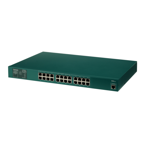
Page 11: Part Names And Functions
1.3. Part Names and Functions Figure 1-1 Part names... - Page 12 ● Power port Connect the supplied power cord into the port and connect the other end into an electric outlet. ● Power cord hook block 10/100/1000BASE-T port (ports 1 to 24) supporting PoE power supply supports IEEE802.3af PoE power supply. Connect a Powered Device supporting IEEE802.3af.
- Page 13 The button operation allows to configure the LED base mode and Loop detection and blocking function (OFF/ON.) Operation Description Press-and-hold Switching Hub the LED base mode settings. When the LED display button is for 3 seconds pressed and held for 3 seconds or more, all of the STATUS/ECO, PoE, or more GIGA, 100M, and FULL LEDs are lit.
-
Page 14: Led Behavior
1.4. LED Behavior 1.4.1. LED Behavior at Starting-up When you turn on this Switching Hub, all LEDs are lit momentarily. Then, the hard- ware self diagnosis is executed. When self-diagnosis is complete and the Power and STATUS/ECO mode LEDs are lit green, Switching Hub operation starts. -
Page 15: Led Behavior While Operating
1.4.2. LED Behavior while Operating This Switching Hub has a set of LEDs for each port. These LEDs indicate the opera- tion status of each port. ● System LED Behavior Description Power LED Green Power On (POWER) Light Power Off Collision LED Orange Packet collisions in either of ports operating in half-... - Page 16 ● Port LED display mode In the Status mode described later, the port LED indicates link-up and communica- tion status. Pressing "LED display Switching Hub button" on the front panel allows to change the port LED display mode as follows: Port LED display mode Description STATUS/ECO...
- Page 17 Port LED (Left) Port LED (Right) Figure 1-2 Port LEDs...
-
Page 18: Loop Detection And Blocking Function
1.4.3. Loop Detection and Blocking Function When a port causes a loop, the corresponding LED lights up in orange. In this case, the port is automatically blocked (default setting: 60 seconds) to prevent a loop. If the loop is not resolved, the port will be blocked again. Resolve the loop while the port is blocked. -
Page 19: Operation Overview Of Poe Power Supply Function
1.5. Operation Overview of PoE Power Supply Function Ports 1 to 24 can support IEEE802.3af compatible PoE power supply. The Switching Hub can supply power up to 15.4 W per port, and up to 124 W in total. ● Power supply operation when the PoE limit LED is blinking orange (the whole unit is overloaded) When the whole unit is overloaded due to a power request exceeding the limit, you can check which port has stopped supplying power, by switching the LED dis-... -
Page 20: Led Display Switch Button Operation
1.6. LED Display Switch Button Operation 1.6.1. LED Base Mode Configuration You can select either of the two LED display modes for this Switching Hub: "Status mode" and "ECO mode." The mode selected immediately after system boot is called "Base mode." By press- ing and holding the LED display switch button for 3 seconds or more, you can switch the Base mode. -
Page 21: Led Display Switch
1.6.2. LED Display Switch Pressing the "LED display switch button" on the front panel allows to change the port LED display in an order as follows: Port LED display mode Description STATUS/ECO Displays link establishment and communication status. Displays power supply status to the connected devices. GIGA Displays link-up status in 1000 Mbps. -
Page 22: Installation
2. Installation Switch-S24GPWR can be installed on a steel product, in a 19-inch rack. 2.1. Installing in a 19-inch Rack Take out two mount brackets and eight screws (for securing the mount brackets to the Switching Hub) from accessories, and secure a bracket to each of the right and left sides of the Switching Hub via four screw holes. -
Page 23: Connection
3. Connection 3.1. Connecting a Twisted Pair Port ● Connection Cable Use a CAT5E or higher straight cable (twisted pair cable) with 8P8C RJ45 modular plugs. ● Network Configuration 100 m or shorter 100 m or shorter 100 m or shorter Figure 3-4 Connection configuration example The length of the cable connecting this Switching Hub and a device must be 100 m or shorter. -
Page 24: Connecting To Power
3.2. Connecting to Power Connect the supplied power cord to the power port of this Switching Hub, and connect the power plug into an electric outlet. The Switching Hub operates at AC 100 to 240 V (50/60 Hz). It does not have a power Switching Hub. When you connect the power plug, the Switching Hub turns on and starts operating. -
Page 25: Configuration
4. Configuration Upon power on, this Switching Hub starts working as a normal switching Hub. To use the SNMP functions and other functions, you need to configure the Switching Hub by using the console, Telnet, SSH, or WEB control screen. In this chapter, the configuration of this Switching Hub is explained. -
Page 26: Login
4.1. Login If you access the Switching Hub via console, the screen displays as shown in Figure. 4-1. If no similar window is displayed, make sure the transmission mode of console is correct or hit the enter key. ============================================================================== PN25249 Local Management System Version x.x.x.xx MAC Address: xx:xx:xx:xx:xx:xx ============================================================================== Login Menu... - Page 27 On the login screen, similar to Figure 4-5 or Figure 4-6, enter the login name. The Switching Hub's default login name is set to "manager". Enter "manager" and press the Return key. Then, you need to enter a password, as Figure 4-7 displays. The Switching Hub's default password is the same as the login name ("manager").
-
Page 28: General Information Menu
4.2. General Information Menu On the Main Menu, pressing "G" opens the General Information Menu screen, as shown in Fig. 4-8. This screen displays this Switching Hubs basic information. You cannot edit shown information on this screen. PN25249 Local Management System Main Menu ->... - Page 29 Screen Description System up for Displays the cumulative time since the power on of this Switching Hub. Boot / Runtime Displays this Switching Hub's firmware version. Code Version The left side displays the Boot Code, and the right side displays the Runtime Code.
-
Page 30: System Administration Configuration
Configuration Menu screen, as shown in Fig. 4-9. On this screen, you can set administrative information, such as device name. PN25249 Local Management System Basic Switch Configuration -> System Admin. Configuration Menu Description: Switch-S24GPWR Name: -------------------------------- <COMMAND> ----------------------------------- Set System [N]ame [Q]uit to previous menu Command>... - Page 31 Screen Description Description Displays the system information. This item is not editable. Name Displays the system name. The factory default setting is blank. Available commands are listed below. Set/edit the system name. Press "N." The command prompt changes to "Enter system name>." Enter a switch name in 50 characters or less.
-
Page 32: System Ip Address Configuration
4.2.2. System IP Address Configuration On the Basic Switch Configuration Menu, pressing "I" opens the System IP Config- uration Menu screen, as shown in Fig. 4-10. On this screen, you can set IP address related settings for this Switching Hub. PN25249 Local Management System Basic Switch Configuration ->... - Page 33 Available commands are listed below. Set/edit the IP address. Press "I." The command prompt changes to "Enter IP address>." Enter the IP address for the Switching Hub. Set/edit the subnet mask. Press "M." The command prompt changes to "Enter subnet mask>." Enter the subnet mask for the Switching Hub.
- Page 34 1. Product Outline Switch-S24GPWR is a Layer-2 Ethernet Switching Hub with management func- tions, equipped with 24 10BASE-T/100BASE-TX/1000BASE-T (auto-negotiation) twisted pair ports supporting IEEE802.3af-compatible PoE power supply function. 1.1. Features * This Switching Hub can supply power conforming with IEEE802.3af. Supplying power up to 15.4 W per port, and up to 124 W in total is possible.
-
Page 35: Basic Switch Configuration
4.3. Basic Switch Configuration On the Main Menu, pressing "B" opens the Basic Switch Configuration Menu screen, as shown in Fig. 4-11. On this screen, you can configure the basic configu- ration settings, such as IP address, ports, MNO series power saving mode. PN25249 Local Management System Main Menu ->... - Page 36 Screen Description System Administration Configura- Configures the management information settings, such as tion Switching Hub name used for SNMP, place, and contact. System IP Configuration Configures the IP address related network information. Port Configuration Basic Configure PoE for each port. Port Configuration Extend Configures the extended port settings, such as port name.
-
Page 37: Port Configuration Basic
4.3.2. Port Configuration Basic On the Basic Switch Configuration Menu, pressing "p" opens the Port Configura- tion Basic Menu screen, as shown in Fig. 4-12. On this screen, you can configure port status display settings and port settings. PN25249 Local Management System Basic Switch Configuration ->... - Page 38 Screen Description Port Displays the port number. Trunk Displays the group number for a trunked port. Type Displays the port type. 100TX The port type is 10/100BASE-TX. 1000T The port type is 10/100/1000BASE-T. Admin Displays the current port status. For all ports, "Enabled" is the factory default setting. Enabled The port is available.
- Page 39 Available commands are listed below. Display the next page. Press "N" to display the next page. Display the previous page. Press "P" to display the previous page. Enable/disable a port. 1. Press "A." The command prompt changes to "Select port number to be changed>." Enter a port number you wish to configure.
-
Page 40: Port Configuration Extend
4.3.3. Port Configuration Extend On the Basic Switch Configuration Menu, pressing "e" opens the Port Configura- tion Extend Menu screen, as shown in Fig. 4-13. On this screen, you can configure port status display settings and extended port settings. PN25249 Local Management System Basic Switch Configuration ->... - Page 41 Assign a name to each port. 1. Press "A." The command prompt changes to "Select port number to be changed>." Enter a port number you wish to configure. (To configure all ports at once, enter "0" as the port number.) 2.
-
Page 42: Port Configuration Power Saving
4.3.4. Port Configuration Power Saving In this Switching Hub, it is possible to reduce power consumption by utilizing our original function "MNO series power saving mode" that detects the connection sta- tus of ports automatically and saves power consumption to minimum, and the Energy Efficient Ethernet (hereinafter referred to as EEE) of IEEE802.3az respec- tively. - Page 43 Mode Displays the communication speed and full-duplex/half-duplex settings. For all ports, "Auto" is the factory default setting. Auto Auto negotiation mode 100-FDx(100F) 100 Mbps full-duplex 100-HDx(100H) 100 Mbps half-duplex 10-FDx(10F) 10 Mbps full-duplex 10-HDx(10H) 10 Mbps half-duplex Power-Saving Displays the status of the MNO series power saving mode. For all ports, "Half"...
-
Page 44: System Security Configuration
4.3.5. System Security Configuration On the Basic Switch Configuration Menu, pressing "S" opens the System Security Configuration screen, as shown in Fig. 4-15. On this screen, you can configure the various settings for accessing this Switching Hub for configuration and manage- ment. - Page 45 Disabled: Access is disabled. IP Setup Inter- Displays the access settings for the IP address configuration software, bundled with the Panasonic network cameras. "Enabled" is the factory default setting.* face: For instructions, refer to Appendix C. Enabled: Access is enabled.
- Page 46 Available commands are listed below. Configure the idle timeout settings for automatically terminating a console-connected session if no input is made. Press "C." The command prompt changes to "Enter console idle timeout>." Enter a value from 0 to 60 (minutes). Entering "0" disables the automatic termination. Configure the idle timeout settings for automatically terminating a Telnet-connected session if no input is made.
-
Page 47: Telnet Access Limitation Configuration
4.3.5.a. Telnet Access Limitation Configuration On the System Security Configuration Menu, pressing "A" opens the Telnet Access Limitation screen, as shown in Fig. 4-1. On this screen, you can configure limitation of equipment accessing to this Switching Hub via Telnet. PN25249 Local Management System System Security Configuration ->... - Page 48 Delete a range of IP address that has been set up. Press "D." The command prompt changes to "Enter IP address entry number>." Enter an IP address entry number you wish to delete. M Change a range of IP address that has been set up. 1.
-
Page 49: Led Base Mode Configuration
4.3.5.b. LED Base Mode Configuration On the System Security Configuration Menu, pressing "B" opens the LED Base Mode Configuration screen, as shown in Fig. 4-2. On this screen, you can configure the LED base mode settings. PN25249 Local Management System System Security Configuration ->... -
Page 50: Forwarding Database
4.3.6. Forwarding Database On the Basic Switch Configuration Menu, pressing "F" opens the Forwarding Data- base Information Menu screen, as shown in Fig. 4-3. On this screen, a list of MAC address tables required for transferring packets that have been learned and recorded is displayed. -
Page 51: Sntp Configuration
4.3.7. SNTP Configuration In this Switching Hub, it is possible to set the time accurately by synchronizing the internal clock to an external SNTP server's clock via SNTP (Simple Network Time Protocol). On the Basic Switch Configuration Menu, pressing "T" opens the SNTP Configura- tion Menu screen, as shown in Fig. - Page 52 Available commands are listed below. Set the IP address of the SNTP server. Press "P." The command prompt changes to "Enter new IP address>." Enter the IP address of the SNTP server. Set the interval time for SNTP synchronization. Press "I." The command prompt changes to "Enter Interval Time>." Enter the interval of time synchronization with the SNTP server with a value of 1 to 1440 (minutes).
-
Page 53: Arp Table Configuration
4.3.8. ARP Table Configuration On the Basic Switch Configuration Menu, pressing "R" opens the ARP Table screen, as shown in Fig. 4-5. On this screen, you can refer to and configure the ARP table. PN25249 Local Management System Basic Switch Configuration -> ARP Table Sorting Method : By IP ARP Age Timeout : 7200 seconds... - Page 54 Available commands are listed below. Display the next page. Press "N" to display the next page. Display the previous page. Press "P" to display the previous page. Set the age-out time of the ARP table. Press "T." The command prompt changes to "Enter ARP age timeout value >." Enter the age- out time of the ARP table with a value of 30 to 86400 (seconds).
-
Page 55: Mac Address Learning Mode Configuration
4.3.8.a. MAC Address Learning Mode Configuration On the Forwarding Database Information Menu, pressing "A" opens the MAC Learning Menu screen, as shown inFig. 4-6. On this screen, you can configure the learning mode settings of the MAC address by port. PN25249 Local Management System Forwarding Database Menu ->... - Page 56 Switching Hub the learning mode of the MAC address. 1. Press "S." The command prompt changes to "Select Port Number to be changed>." Enter a port number for which you wish to change the setting. 2. Then, the command prompt changes to "Change MAC Learning Mode for port #(specified port number)>."...
-
Page 57: Display Of Mac Address Table By Port
4.3.8.b. Display of MAC Address Table by Port On the Forwarding Database Information Menu, press "P." The command prompt changes to "Enter Port Number>." Specifying a port number opens the Display MAC Address by Port screen as shown in Fig. 4-7. On this screen, you can display the MAC address table by port. -
Page 58: Display Of All Mac Addresses
4.3.8.c. Display oF All MAC Addresses On the Forwarding Database Information Menu, pressing "M" opens the Display MAC Address by MAC screen, as shown in Fig. 4-8. On this screen, you can display all the MAC address tables in this Switching Hub. PN25249 Local Management System Forwarding Database Menu ->... -
Page 59: Display Of Mac Address Table By Vlan
4.3.8.d. Display of MAC Address Table by VLAN On the Forwarding Database Information Menu, press "V." The command prompt changes to "Enter VLAN ID>." Specifying a port number opens the Display MAC Address by VLAN ID screen as shown in Fig. 4-9. On this screen, you can display the MAC address table by VLAN. -
Page 60: Addition Or Deletion Of Mac Address
4.3.8.e. Addition Or Deletion Of MAC Address On the Forwarding Database Information Menu, pressing "S" opens the Static Address Table Menu screen, as shown in Fig. 4-10. On this screen, you can add or delete MAC addresses statically. PN25249 Local Management System Forwarding Database Menu ->... -
Page 61: Advanced Switch Configuration
4.4. Advanced Switch Configuration On the Main Menu, pressing "A" opens the Advanced Switch Configuration Menu screen, as shown in Fig. 4-11. On this screen, you can configure the settings of VLAN, Link Aggregation, Port Monitoring, QoS, Power Over Ethernet and Loop detection and blocking function for this Switching Hub. - Page 62 Screen Description VLAN Management Configures the VLAN-related settings. Link Aggregation Configures the link aggregation settings. Port Monitoring Configura- Configures the port monitoring settings. tion Quality of Service Configu- Configure the QoS settings. ration Power Over Ethernet Con- Configures the PoE power supply settings. figuration Loop Detection Configura- Configures the loop detection and blocking function settings.
-
Page 63: Vlan Management
4.5.1. VLAN Management 4.5.1.a. Special Features ・ Corresponding to IEEE802.1Q Tag VLAN, the VLAN can send frames with a VLAN tag (hereinafter, called as just "tag") attached. ・ It has two different parameters: VLAN ID and PVID. The destination of untagged frames is determined by a combination of these parameters. -
Page 64: Vlan Management Menu
4.5.1.b. VLAN Management Menu On the Advanced Switch Configuration Menu, pressing "V" opens the VLAN Man- agement Menu screen, as shown in Fig. 4-12. On this screen, you can configure the VLAN-related settings. PN25249 Local Management System Advanced Switch Configuration -> VLAN Management Menu Total VLANs : 1 VLAN ID VLAN Name VLAN Type... - Page 65 Move to the VLAN creation screen. Press "C." The screen changes to "VLAN Create Menu." For details, refer to the next section (4.5.1.c). Delete a VLAN that has been configured. Press "D." The command prompt changes to "Enter VLAN ID >." Enter the VLAN ID you wish to delete with a value of 2 to 4094.
-
Page 66: Vlan Creation Menu
4.5.1.c. VLAN Creation Menu On the VLAN Management Menu, pressing "C" opens the VLAN Creation Menu screen, as shown in Fig. 4-13. On this screen, you can create a VLAN. PN25249 Local Management System VLAN Management -> VLAN Creation Menu VLAN ID VLAN Name Port Members... - Page 67 Available commands are listed below. Set the VLAN ID (VLAN Identifier). Press "V." The command prompt changes to "Set VLAN ID->Enter VLAN ID >." Enter a new VLAN ID. Set the name of the VLAN. Press "N." The command prompt changes to "Set VLAN name->Enter VLAN name >." Enter a new VLAN name in 30 characters or less.
-
Page 68: Vlan Modification Menu
4.5.1.d. VLAN Modification Menu On the VLAN Management Menu, pressing "o" and specifying the target VLAN ID open the VLAN Modification Menu screen, as shown in Fig. 4-14. On this screen, you can modify VLAN-related setting information. PN25249 Local Management System VLAN Management ->... - Page 69 Available commands are listed below. Set the name of the VLAN. Press "N." The command prompt changes to "Set VLAN name->Enter VLAN name >." Enter a new VLAN name in 30 characters or less. Set the VLAN members. Press "P." The command prompt changes to "Enter egress port number >." Enter a port num- ber.
-
Page 70: Vlan Port Configuration Menu
4.5.1.e. VLAN Port Configuration Menu On the VLAN Management Menu, pressing "S" opens the VLAN Port Configuration Menu screen, as shown in Fig. 4-15. On this screen, you can configure the VLAN- related settings by port. PN25249 Local Management System VLAN Management ->... - Page 71 Available commands are listed below. Display the next page. Press "N" to display the next page. Display the previous page. Press "P" to display the previous page. Configure the PVID settings. 1. Press "V." The command prompt changes to "Enter port number>." Enter the port num- ber you wish to configure.
-
Page 72: Link Aggregation
4.5.2. Link Aggregation 4.5.2.a. About Link Aggregation Link Aggregation is a function that can duplicate the cable and increase the band- width between switches by grouping multiple Switching Hub ports (called trunk- ing) for connection. In this Switching Hub, it is possible to create up to 8 groups, each of which includes up to 8 ports. -
Page 73: Trunk Configuration Menu
4.5.2.b. Trunk Configuration Menu On the Advanced Switch Configuration Menu, pressing "L" opens the Trunk Con- figuration Menu screen, as shown in Fig. 4-16. On this screen, you can configure the trunking settings. PN25249 Local Management System Advanced Switch Configuration -> Trunk Configuration Menu Mode Member Port List ----- -------- ---------------------------------------------------------------... - Page 74 Remove trunking settings. 1. Press "R." The command prompt changes to "Enter trunk group admin key>." Enter the group number you wish to delete. 2. The command prompt changes to "Enter port member port for group key #>." Enter a port number you wish to do delete.
-
Page 75: Port Monitoring Configuration
4.5.3. Port Monitoring Configuration On the Advanced Switch Configuration Menu, pressing "M" opens the Port Moni- toring Configuration Menu screen, as shown in Fig. 4-17. In this Switching Hub, when analyzing communication using a protocol analyzer, etc., it is possible to monitor other port's packet that cannot be obtained under normal conditions because of being filtered. - Page 76 Available commands are listed below. Set a destination port (port to which the analyzer, etc. is connected) of the monitored data. Press "S." The command prompt changes to "Enter port number>." Enter the target port number. Configure a port to be monitored. Press "M."...
-
Page 77: Quality Of Service Configuration
4.5.4. Quality of Service Configuration On the Advanced Switch Configuration Menu, pressing "C" opens the Quality of Service Configuration Menu screen, as shown in Fig. 4-18. On this screen, you can configure the settings of QoS (Quality of Service) of the Switching Hub. PN25249 Local Management System Advanced Switch Configuration Menu ->... -
Page 78: Traffic Class Configuration Menu
4.5.4.a. Traffic Class Configuration Menu On the Quality of Service Configuration Menu, pressing "T" opens the Traffic Class Configuration screen, as shown in Fig. 4-19. On this screen, you can configure the QoS and Traffic Class settings. PN25249 Local Management System Quality of Service Configuration ->... -
Page 79: Diffserv Configuration Menu
4.5.4.b. DiffServ Configuration Menu On the Quality of Service Configuration Menu, pressing "D" opens the DiffServ Configuration screen, as shown in Fig. 4-20. On this screen, you can configure the DiffServ settings using DSCP values. PN25249 Local Management System Quality of Service Configuration -> Diffserv Configuration Menu Diffserv Status : Disabled 0 : Lowest 3 : Highest DSCP Priority DSCP Priority DSCP Priority DSCP Priority DSCP Priority... -
Page 80: Power Over Ethernet Configuration
4.5.5. Power Over Ethernet Configuration On the Advanced Switch Configuration Menu, pressing "P" opens the Power Over Ethernet Configuration Menu screen as shown in Fig. 4-21. On this screen, you can configure IEEE802.3af power supply settings. PN25249 Local Management System Advanced Switch Configuration ->... -
Page 81: Poe Port Configuration Menu
4.5.5.a. PoE Port Configuration Menu On the Power Over Ethernet Configuration Menu, pressing "P" opens the PoE Port Configuration Menu screen, as shown in Fig. 4-22. On this screen, you can config- ure the PoE settings for each port. PN25249 Remote Management System Power Over Ethernet Configuration ->... - Page 82 Screen Description Admin Displays whether or not power supply is possible. The factory default setting is "Up." Power supply is possible. Down Power supply is not possible. Sche. Displays the PoE scheduler function status. Indicates that the power supply to the PoE is turned on by the PoE scheduler.
- Page 83 Available commands are listed below. Set whether the power supply is enabled or disabled. 1. Press "S." The command prompt changes to "Select port number to be changed>." Enter a port number you wish to configure. (To configure all ports at once, enter "0" as the port number.) 2.
-
Page 84: Poe Global Configuration Menu
4.5.5.b. PoE Global Configuration Menu On the Power Over Ethernet Configuration Menu, pressing "G" opens the PoE Global Configuration Menu as shown in Fig. 4-23. On this screen, you can view the PoE settings. PN25249 Local Management System Power Over Ethernet Configuration -> PoE Global Configuration Menu Power Budget : 124W Power Consumption :... -
Page 85: Poe Schedule Configuration Menu
4.5.5.c. PoE Schedule Configuration Menu On the Power Over Ethernet Configuration Menu, pressing "S" opens the PoE Schedule Configuration Menu screen as shown in Fig. 4-24. On this screen, you can configure the PoE scheduler settings. PN25249 Local Management System Power Over Ethernet Configuration ->... -
Page 86: Port List Configuration Menu
4.5.5.d. Port List Configuration Menu On the PoE Schedule Configuration Menu, pressing "P" opens the Port List Config- uration Menu screen, as shown in Fig. 4-25. On this screen, you can set/delete a port number to be operated on the PoE scheduler. PN25249 Local Management System PoE Schedule Configuration ->... - Page 87 Available commands are listed below. Display the next page. Press "N" to display the next page. Display the previous page. Press "P" to display the previous page. Create a port list. Press "C" to move to the "Port List Creation Menu" screen. Refer to 4.5.5.d.1. Delete a port list.
- Page 88 4.5.5.d.1. Port List Creation Menu On the Port List Configuration Menu, pressing "C" opens the Port List Creation Menu screen, as shown in Fig. 4-26. On this screen, you can set/delete a port num- ber for which the PoE scheduler is operated. PN25249 Local Management System Port List Configuration ->...
-
Page 89: Schedule Configuration Menu
4.5.5.e. Schedule Configuration Menu On the PoE Schedule Configuration Menu, pressing "S" opens the Schedule Config- uration Menu screen, as shown in Fig. 4-27. On this screen, you can configure the settings of time (month, week, day, specified date) to operate on the PoE sched- uler and power supply control. - Page 90 Action Displays the number of created port lists. Turns on the PoE. Turns off the PoE. OFF/ON Turns off the PoE and then turns it on (RESTART). Status Displays the PoE schedule function status by port. Enable Enables the PoE schedule function by port. Disable Disables the PoE schedule function by port.
- Page 91 Available commands are listed below. Display the next page. Press "N" to display the next page. Display the previous page. Press "P" to display the previous page. Enable/disable the PoE scheduler. Press "G." The command prompt changes to "Enable or Disable Global Status (E/D) >." Press "E"...
- Page 92 4.5.5.e.1. Create Schedule Configuration Menu On the PoE Schedule Configuration Menu, pressing "C" opens the Create Schedule Configuration Menu screen, as shown in Fig. 4-28. On this screen, you can config- ure the settings of time (month, week, day, specified date) to operate on the PoE scheduler and power supply control.
- Page 93 Available commands are listed below. Set the index number of the schedule. Press "S." The command prompt changes to "Enter PoE Schedule index >." Enter an index number between 1 and 65535. (Maximum number to be set: 32) Set the name of the schedule. Press "N."...
- Page 94 4.5.5.e.2. Date list Configuration Menu On the PoE Schedule Configuration Menu, pressing "I" opens the Date list Configu- ration Menu screen, as shown in Fig. 4-29. On this screen, you can configure the settings of the date list of the PoE scheduler. PN25249 Local Management System Create Schedule Configuration ->...
- Page 95 Available commands are listed below. Display the next page. Press "N" to display the next page. Display the previous page. Press "P" to display the previous page. Create a date list. Press "R" to move to the "Create Date List Menu" screen. Delete a date list.
- Page 96 4.5.5.e.3. Create Date List Menu On the PoE Schedule Configuration Menu, pressing "S" opens the Create Date List Menu screen, as shown in Fig. 4-30. On this screen, you can configure the settings of the date list for execution of schedules. Set the year, month, and date on the date list.
- Page 97 Available commands are listed below. Set the index number of the date list. Press "I." The command prompt changes to "Enter Date List index >." Enter an index number between 1 and 65535. Set the year in which the date list is executed. Press "S."...
-
Page 98: Loop Detection Configuration Menu
4.5.6. Loop Detection Configuration Menu On the Advanced Switch Configuration Menu, pressing "D" opens the Loop Detec- tion Configuration Menu screen as shown in Fig. 4-31. On this screen, you can con- figure the Loop detection and blocking function settings. For network configuration, refer to Appendix D "Network Configuration Example and Notes Using Loop Detection and Blocking Function"... - Page 99 Mode Shows the mode of Loop detection behavior. Block When the Switching Hub detects loop, the ports are blocked. (Factory default setting) Shutdown When the Switching Hub detects loop, the ports are shut down. Recovery Displays the status of the Recovery mode that can automatically recover a blocked port.
-
Page 100: Loop History Information
4.5.6.a. Loop History Information On the Loop Detection Configuration Menu, pressing "I" opens the Loop History Information screen, as shown in Fig. 4-32. On this screen, you can view the loop detection date and time and a list of event information. PN25249 Local Management System Loop Detection Configuration Menu ->... -
Page 101: Statistics
4.6. Statistics On the Main Menu, pressing "S" opens the Statistics Menu screen as shown in Fig. 4-33. On this screen, you can monitor the number of packets as statistics informa- tion of the Switching Hub and thereby keep an eye on the network status. In addi- tion, monitoring of error packets allows you to segregate failures. - Page 102 Reset counter values. Press "R." The counter values are reset and immediately changed to those accumulated after resetting the counters. Set the display refresh mode. Press "F." The command prompt changes to "1 for start to refresh,2 for set refresh rate." Press "1"...
- Page 103 Available commands are listed below. Switching Hub the port to display the values. Press "S." The command prompt changes to "Select Port number>." Enter the port number for which you wish to display values. Display the values of the next port. Press "N."...
- Page 104 Over 1024 Pkts Displays the total number of packets that have a packet length of 1024 bytes or greater. *This items is displayed with Jumbo Status Disabled. Note: This screen is set to refresh at the refresh intervals. Therefore, if the timeouts of the console, SSH, and Telnet are set to be longer than the refresh interval, timeouts do not occur.
-
Page 105: Switch Tools Configuration
4.7. Switch Tools Configuration On the Main Menu, pressing "T" opens the Switch Tools Configuration screen as shown in Fig. 4-35. On this screen, you can use and configure the switch tools for firmware upgrade, upload/download of configuration files, system reboot, log viewing, etc. -
Page 106: Tftp Software Upgrade
4.7.1. TFTP Software Upgrade On the Switch Tools Configuration Menu, pressing "T" opens the TFTP Software Upgrade screen as shown in Fig. 4-36. On this screen, you can execute and config- ure firmware upgrades. PN25249 Local Management System Switch Tools Configuration -> TFTP Software Upgrade Image Version: x.x.x.xx TFTP Server IP:... - Page 107 When the download starts, the screen shown in Fig. 4-37 opens, and you can check the download status. (By pressing Ctrl+c keys during transmission, you can interrupt the TFTP transmis- sion process.) After the download completes, the system is automatically rebooted, and the login screen opens.
-
Page 108: Configuration File Upload/Download
4.7.2. Configuration File Upload/Download On the Switch Tools Configuration Menu, pressing "C" opens the Configuration File Upload/Download Menu screen as shown in Fig. 4-38. On this screen, you can exe- cute and configure upload/download of the configuration file of this Switching Hub to/from a PC. - Page 109 Available commands are listed below. Set the IP address of the TFTP server that executes upload/download of the configuration file. Press "S." The command prompt changes to "Enter IP address of TFTP server>." Enter the IP address of the TFTP server. Set the name of the configuration file to be uploaded/downloaded.
-
Page 110: System Reboot
4.7.3. System Reboot On the Switch Tools Configuration Menu, pressing "R" opens the System Reboot Menu screen as shown in Fig. 4-39. On this screen, you can reboot this Switching Hub. PN25249 Local Management System Switch Tools Configuration -> System Reboot Menu Reboot Status: Stop Reboot Type:... - Page 111 Available commands are listed below. Set the reboot type to normal reboot or factory default. Press "O." The command prompt changes to "Select reboot option (N/F/I)>." Press "N" to set the type to normal reboot, "F" to return it to factory default, or "I" to save only the IP address setting and return the other settings to factory default.
-
Page 112: Exception Handler
4.7.4. Exception Handler On the Switch Tools Configuration Menu, pressing "X" opens the Exception Han- dler screen as shown in Fig. 4-40. On this screen, you can configure the exception handling operations. PN25249 Local Management System Switch Tools Configuration -> Exception Handler Exception Handler: Disabled Exception Handler Mode:... - Page 113 Available commands are listed below. Enable/disable the exception handling function. Press "X." The command prompt changes to "Enable or Disable Exception Handler (E/D)>." Press "E" to enable the function. Press "D" to disable it. M Set the exception handling method. Press "M."...
-
Page 114: Ping Execution
4.7.5. Ping Execution On the Switch Tools Configuration Menu, pressing "P" opens the Ping Execution screen as shown in Fig. 4-41. On this screen, you can execute the ping command from the Switching Hub to confirm communications with connected terminals and other devices. - Page 115 Available commands are listed below. Set the IP address of the target of the ping. Press "I." The command prompt changes to "Enter new Target IP Address >." Enter the IP address. Set the number of times of ping. Press "N." The command prompt changes to "Enter new Request Times >." Enter the num- ber of times between 1 and 10.
-
Page 116: System Log
4.7.1. System Log On the Switch Tools Configuration Menu, pressing "L" opens the System Log Menu screen as shown in Fig. 4-43. This screen displays logs of events caused to the Switching Hub. By viewing events, you can check activities related to the Switching Hub, which is useful information for network management. - Page 117 Available commands are listed below. Display the next page. Press "N" to display the next page. Display the previous page. Press "P" to display the previous page. Clear all system logs. Press "C" to clear all system logs. Displayed the entry log number. Press "S."The command prompt changes to "Select entry log number>."Set the range from 1 to 1024, 0 for last entry.
-
Page 118: Enable/Disable Individual System Log
4.7.1.a. Enable/Disable Individual System Log On the System Log Menu, pressing "I" opens the Enable/Disable Individual System Log Menu screen as shown in Fig. 4-44. On this screen, you can change the System Log settings. PN25249 Local Management System System Log -> Enable/Disable Individual System Log Menu Link UP/DOWN : Enabled PoE ON/OFF... -
Page 119: Watch Dog Timer Menu
4.7.2. Watch Dog Timer Menu On the Switch Tools Configuration Menu, pressing "W" opens the Watch Dog Timer Menu screen, as shown in Fig. 4-45. On this screen, you can configure the Watch Dog Timer function settings. PN25249 Local Management System Switch Tools Configuration ->... -
Page 120: Save Configuration To Flash
4.8. Save Configuration to Flash On the Main Menu, pressing "F" opens the Save Configuration to Flash screen as shown in Fig. 4-46. Execute this command to save the Switching Hub configuration to built-in memory. On this screen, the command prompt changes to "Save current configuration?(Y/N)."... - Page 121 PN25249 Local Management System Main Menu -> Save Configuration to Flash Saving configuration to flash is successful, press any key to continue... Fig. 4-47 Save Configuration to Flash Screen: Completed...
-
Page 122: Command Line Interface (Cli)
On this screen, you can use the command line for configuration instead of the menu. Refer to the separate volume "Operation Manual (For CLI)" for configura- tion procedures. Enter "logout" at the command prompt to return to the Menu from CLI. S24GPWR> Fig. 4-48 Command Line Interface (CLI) -
Page 123: Logout
4.10.Logout On the Main Menu, if you access from the console port, pressing "Q" opens the login screen. If you access using Telnet or SSH, then pressing "Q" terminates the connection. Follow the login procedures shown in section 4.2 of Basic Operation Manual to log in again. -
Page 124: Appendix
Appendix 5.1. Specifications ○ Interface - Twisted-pair ports: Ports 1 to 24 (RJ45 connector) Transmission system IEEE802.3 10BASE-T IEEE802.3u 100BASE-TX IEEE802.3ab 1000BASE-T - Console port x 1 (RJ45 connector) RS-232C (ITU-TS V.24) ○ Switching system - Store-and-forward system - Forwarding rate 10BASE-T 14,880 pps... - Page 125 ○ External specifications - Dimensions 44mm (Height) x 440mm( (Width) x 256 mm (Depth) (Excluding protruding sections) - Mass (Weight) 3,600 g...
-
Page 126: Easy Ip Address Setup Function
The following are points to note when using the easy IP address setup function. [Known compatible software] Panasonic Life Solutions Networks Co., Ltd. "ZEQUOassistPLUS" Ver. 1.1.1.0 Panasonic Corporation "Easy IP Setup" V3.01/V4.00/V4.24R00 Panasonic System Networks Co., Ltd. "Easy Config" Ver3.10R00... -
Page 127: Network Configuration Example And Notes Using Loop Detection And Blocking Function
5.3. Network Configuration Example and Notes Using Loop Detection and Blocking Function Configuration example using the Loop detection and blocking function Using the Loop detection and blocking function allows to prevent a loop failure possibly occurring on a downstream Switching Hub that the user directly uses. If you connect a hub that does not support the Loop detection and blocking func- tion to a downstream Switching Hub, and a loop failure occurs in the Switching Hub, the downstream Switching Hub port that caused a loop is blocked to prevent... - Page 128 Notes when using the Loop detection and blocking function - Disable the function on the upstream Switching Hub If you configure a network only with switches having the Loop detection and blocking function, the upstream Switching Hub may detect a loop occurring on the downstream Switching Hub first depending on the condition.
-
Page 129: Troubleshooting
6. Troubleshooting If you find any problem, please take the following steps to check. ◆ LED indicators ■ The power LED (POWER) is not lit. ● Is the power cord connected? Please confirm that the power cord is securely connected to the power port. ●... - Page 130 ◆ PoE power supply is impossible. ■ The PoE power supply LED (PoE) is not lit. ● Is the LED mode set to the Power supply mode (PoE)? → Select the Power supply mode LED (PoE) by pressing the LED switch but- ton.
-
Page 131: After-Sales Service
7. After-sales Service 1. Warranty card A warranty card is included in the operating instructions (paper) provided with this Switching Hub. Be sure to confirm that the date of purchase, shop (com- pany) name, etc., have been entered in the warranty card and then receive it from the shop. - Page 132 (* You can check the version on the screen described in Section 4.2 of the Operation Man- ual - for Menu Interface.) © Panasonic Life Solutions Networks Co., Ltd. 2014-2020 Panasonic Life Solutions Networks Co., Ltd. 2-12-7, Higashi-Shimbashi, Minato-ku, Tokyo Japan, 105-0021 URL: http://panasonic.co.jp/ls/plsnw/english/...
Need help?
Do you have a question about the S24GPWR and is the answer not in the manual?
Questions and answers