
Related Manuals for Nonin Sensmart H500


Summary of Contents for Nonin Sensmart H500
- Page 1 Operator’s Manual ® Sensmart Model H500 Multi-Sensing Portable Oximetry System English...
- Page 2 CO-Met are trademarks or registered trademarks of Nonin Medical, Inc. The Bluetooth word mark and logos are owned by the Bluetooth SIG, Inc. and any use of such marks by Nonin Medical, Inc. is under license. Other trademarks and trade names are those of their respective owners.
-
Page 3: Table Of Contents
Contents Indications for Use ............. 1 Warnings ..................1 Cautions ..................3 Declaration of Conformity with FCC and Canadian Ministry of Health Rules for Electromagnetic Compatibility ..4 Federal Communications Commission (FCC) Notice....5 System Symbols..............6 Display Screens and Symbols .......... 9 COMet .................. - Page 4 Contents (Continued) Parts and Accessories ............. 33 Power Supply Symbols ............33 Compatible Sensors ..............33 Troubleshooting ............... 35 Error Codes ................36 Service, Support, and Warranty ........37 Service and Support ..............37 Warranty ...................37 Technical Information ............39 Manufacturer’s Declaration ............39 Equipment Response Time ............44 Testing Summary ..............45 COHb/MetHb Principles of Operation........
- Page 5 Figures Figure 1. COMet Screen and Symbols .......... 9 Figure 2. SpO Monitoring Screen ..........10 Figure 3. rSO Monitoring Screen ..........11 Figure 4. Unpacking the H500 System ........15 Figure 5. System Set Up.............. 16 Figure 6. D-HH Display ..............17 Figure 7.
- Page 6 Tables Table 1. Labeling and Packaging Symbols ........6 Table 2. Power Supply Labeling and Packaging Symbols..... 8 Table 3. H500 Monitoring Screen Symbols and Indicators ..12 Table 4. H500 Features ............... 17 Table 5. SP-BLE Features ............18 Table 6.
-
Page 7: Indications For Use
• For %SpO2 and pulse rate, the SenSmart H500 System is intended for spot-checking and/or continuous monitoring of adult, pediatric, infant, and neonate patients who are well or poorly perfused, during both motion and non-motion conditions in professional healthcare facilities, mobile, and EMS settings. - Page 8 Indications for Use Warnings (Continued) Always inspect the device before use. Do not use a damaged device or sensor. Before using any sensor, carefully read the sensor instructions for use, which contains sensor application information for each sensor. To prevent improper performance and/or patient injury, verify compatibility of the monitor, sensor(s), and accessories before use.
-
Page 9: Cautions
Indications for Use Cautions When using this device in an operating room, it must remain outside the sterile field. This equipment complies with IEC 60601-1-2 for electromagnetic compatibility (EMC) for medical electrical equipment and/or systems. This standard is designed to provide reasonable protection against harmful interference in a typical medical installation. -
Page 10: Declaration Of Conformity With Fcc And Canadian Ministry Of Health Rules For Electromagnetic Compatibility
(WEEE) 2002/96/EC, do not dispose of this product as unsorted municipal waste. This device contains WEEE materials; please contact your distributor regarding take-back or recycling of the device. If you are unsure how to reach your distributor, please call Nonin for your distributor’s contact information. -
Page 11: Federal Communications Commission (Fcc) Notice
ANSI/IEEE Std. C95.1-2005. The FCC requires the user to be notified that any changes or modifications to this device that are not expressly approved by Nonin Medical, Inc. may void the user’s authority to operate the equipment. NOTE: No modifications to this device are allowed that in any way affect or... -
Page 12: System Symbols
System Symbols System Symbols This chapter describes the symbols that are found on the H500 system components and packaging. Detailed information about functional symbols can be found in "System Components and Set Up" section on page 14 Table 1. Labeling and Packaging Symbols Symbol Description CAUTION! - Page 13 System Symbols Table 1. Labeling and Packaging Symbols (Continued) Symbol Description Date of Manufacture Manufacturer Storage/Shipping Temperature Range Handle With Care. Keep Dry Storage/Shipping Humidity Range Not an Alarm System Lithium-ion Polymer Battery Li-ion Battery Bluetooth Device Address...
-
Page 14: Table 2. Power Supply Labeling And Packaging Symbols
System Symbols Table 2. Power Supply Labeling and Packaging Symbols Symbol Description BSMI Mark, Taiwan Federal Communications Commission PSE Mark, Japan RCM Tick Mark, Australia and New Zealand Medical Power Supply Certification UL Safety Mark for united States and Canada CE Marking indicating conformance to all applicable directives Indoor Use Only Class II, Double Insulated... -
Page 15: Display Screens And Symbols
Display Screens and Symbols Display Screens and Symbols Refer to the following Table for definitions to the numbered items associated with Figures 1-3. COMet #SN05555554 Figure 1. COMet Screen and Symbols... -
Page 16: Pulse Oximetry
Display Screens and Symbols Pulse Oximetry #SN05555554 Figure 2. SpO Monitoring Screen... -
Page 17: Cerebral And Tissue Oximetry
Display Screens and Symbols Cerebral and Tissue Oximetry #SN05555554 Figure 3. rSO Monitoring Screen... -
Page 18: Table 3. H500 Monitoring Screen Symbols And Indicators
Display Screens and Symbols Table 3. H500 Monitoring Screen Symbols and Indicators Symbol Description Display Battery Indicator The display battery indicator shows the approximate percentage of battery life remaining on the display. For signal processor battery information see item number 11. %SpO Percent Functional Hemoglobin Oxygen Saturation Displays dashes until the reading is valid. - Page 19 Display Screens and Symbols Table 3. H500 Monitoring Screen Symbols and Indicators Symbol Description Session ID EXAMPLE: Unique identifier for recorded data file. Date and Time EXAMPLE: The date and time display in 24-hour clock format. To set the date and/or time, see "Setting Date and Time" section on page 29.
-
Page 20: System Components And Set Up
The standard system configuration includes these non-sterile components: • D-HH, Nonin SenSmart handheld display • SP-BLE, Nonin SenSmart Signal Processor, Bluetooth Low Energy • H500-CC, Nonin SenSmart H500 System Carrying Case • H500-PS, Nonin SenSmart H500 Power Supply... -
Page 21: Figure 4. Unpacking The H500 System
System Components and Set Up Figure 4. Unpacking the H500 System... -
Page 22: System Configuration
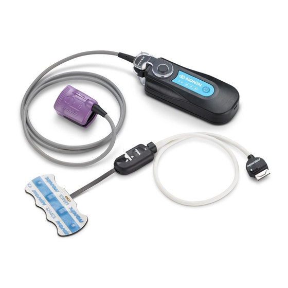
System Components and Set Up System Configuration H500 System in Carry Case with Finger clip sensor attached Figure 5. System Set Up System Display The system display allows the user to view %COHb, %MetHb, %SpO , and pulse rate data. See below for display features and descriptions. For cleaning instructions, refer to "Care and Maintenance"... -
Page 23: Figure 6. D-Hh Display
System Components and Set Up Figure 6. D-HH Display Table 4. H500 Features Description Event Mark Button Momentarily pressing this button marks an event in memory. Events are denoted by increasing numbers. Pressing this button for 0.5 seconds starts a new patient record. On/Off,Sleep Button •... -
Page 24: Signal Processor (Sp-Ble)
System Components and Set Up Signal Processor (SP-BLE) System signal processor calculates all measurements and sends to paired display through a Bluetooth low energy (BLE) wireless connection. Signal processor requires a SenSmart sensor to be applied to the sensor port to take measurement. -
Page 25: Figure 8. Connect Sensor To Signal Processor
System Components and Set Up Connect/Disconnect a Sensor to the Signal Processor To connect: a. Flip the clear lock on the signal processor back to expose the connection port. b. Align the arrows on the sensor connector and the signal processor (Figure 8-A). -
Page 26: Sensors
System Components and Set Up Click the lock into place (Figure 9-B). Figure 9. Signal Processor Lock Replacement Sensors Detailed information regarding specific sensor use (e.g., patient population, body/tissue, application, connecting the sensor to the system) can be found in the respective sensor instructions for use. -
Page 27: System Operation
System Operation System Operation CAUTION: Between patients, turn the H500 system to Sleep Mode. When the device is turned on, the monitor begins a new patient record. WARNING: This device is intended only as an adjunct device in patient assessment. It should not be used as the sole basis for diagnosis or therapy decisions. -
Page 28: Taking A Measurement
System Operation Display will automatically connect to signal processor. Once display has connected to signal processor, measurement screen will display. Taking a Measurement Turn on the display by quickly pressing the power button on the right side of the device. When display is turned on, signal processor automatically engages and the connected sensor LED lights will activate. -
Page 29: Event Marking
#SN05555554 Figure 11. Event Marking Charging the System Display and signal processor must both be charged to use system. Charge the display and signal processor using the provided Nonin chargers. Insert charger into respective display and signal processor charging ports. -
Page 30: Battery
System Operation CAUTION: Charging signal processor at temperatures below 0 degrees °C (32 degrees °F) will decrease battery life. Do not charge signal processor at temperatures below 0 °C (32 °F). Battery For more information, see the “Internal Power” section in "Specifications" section on page 48. -
Page 31: Placing Device In Long-Term Storage Mode
System Operation Placing Device in Long-Term Storage Mode When not using device daily or for storing for long periods of time, life can be extended by placing the device into Long-Term Storage Mode. Press and hold On/Off button on display until screen prompt appears Choose “Power Off”... -
Page 32: Figure 13. Data Download Screen 1- Select Menu Icon
System Operation NOTE: If the transfer file icon is not shown on the display, no records are present to transfer. Display will show data download screen 1. Tap menu icon in upper left of screen: Press upper left icon to select the memory stick. -
Page 33: Figure 15. Data Download Screen 3- Select Files To Transfer
System Operation Tap to select files to transfer and choose the SELECT button. Data download will begin automatically once files are selected: Press the SELECT button to store all available records to the memory stick. Figure 15. Data Download Screen 3- Select Files to Transfer Data transfer is successful if the File Transfer icon has been replaced with a checkmark symbol, as shown below. -
Page 34: Figure 17. Download Data Files
System Operation To view downloaded files: Disconnect memory stick from data download cable. Connect memory stick to computer USB port. Open desired file using Microsoft Excel: Figure 17. Download Data Files... -
Page 35: Setting Date And Time
System Operation Setting Date and Time Date and time must be set manually. To set data and time: Turn on the display to show Welcome screen. Tap the date and time on top of Welcome screen ONE time: From the Welcome screen, press the Date and time three... -
Page 36: Bluetooth Technology
Nonin’s use of Bluetooth wireless technology allows information to be transmitted through a Bluetooth radio to a compatible Bluetooth-enabled device. Nonin’s wireless system removes the need for a physical connection from the H500 monitor to a remote monitor location, giving increased ability to move the monitor freely. -
Page 37: Care And Maintenance
Care and Maintenance Care and Maintenance The advanced digital circuitry within the Model H500 system components requires no calibration or periodic maintenance. Do not attempt to open the case of any of the system components or repair the electronics. Opening the case will damage the component and void the warranty. - Page 38 Care and Maintenance WARNING: Protect from exposure to water or any other liquid, with or without AC power. CAUTION: Do not place the device in liquid or clean it with agents containing ammonium chloride, isopropyl alcohol, or products that are not listed in this operator’s manual.
-
Page 39: Parts And Accessories
Parts and Accessories Parts and Accessories For more information about Nonin parts and accessories, visit www.nonin.com or contact Nonin at (800) 356-8874 (USA and Canada), +1 (763) 533-9968, or +31 (0)13 - 79 99 040 (Europe). Model Description Charger H500-PS... - Page 40 Intermediate Cable NOTE: For use with SenSmart SpO -only sensors only. WARNING: Use the Model H500 only with charger supplied by Nonin Medical. WARNING: The use of signal processors, sensors, accessories, and cables other than those in the Parts and Accessories List may or will result in increased electromagnetic emission and/or decreased immunity of this device.
-
Page 41: Troubleshooting
Refer to error code on display and reference below for solution. If these solutions do not correct the problem, please contact Nonin Technical Service at (800) 356-8874 (USA and Canada), +1 (763) 553-9968, or +31 (0)13 - 79 99 040 (Europe). -
Page 42: Error Codes
Attempt connection again. failed. Connection may have If problem persists, contact taken too long to open. Nonin. COM-02 Wireless connection Contact Nonin. rejected, likely due to pairing mismatch. OXI-01 SP-BLE is not sending Attempt connection again. critical data. Power the device off and then on. -
Page 43: Service, Support, And Warranty
Warranty NONIN MEDICAL, INCORPORATED, (Nonin) warrants to the purchaser, for a period of 1 year from the date of purchase, each Model H500 battery. Nonin warrants the H500 display and H500 signal processor for a period of 2 years from the date of purchase. Please consult your local Nonin distributor for additional information. - Page 44 Service, Support, and Warranty This warranty excludes cost of delivery to and from Nonin. All repaired units shall be received by the purchaser at Nonin's place of business. Nonin reserves the right to charge a fee for a warranty repair request on any device that is found to be within specifications.
-
Page 45: Technical Information
Technical Information Technical Information NOTE: This product complies with ISO 10993, Biological Evaluation of Medical Devices Part 1: Evaluation and Testing. CAUTION: A functional tester cannot be used to assess the accuracy of the oximeter monitor or sensor. CAUTION: Portable and mobile RF communications equipment can affect medical electrical equipment. -
Page 46: Table 7. Electromagnetic Immunity
Technical Information Table 7. Electromagnetic Immunity IEC 60601 Test Compliance Electromagnetic Immunity Test Level Level Environment—Guidance This device is intended for use in the electromagnetic environment specified below. The customer and/or user of this device should ensure that it is used in such an environment. Electrostatic ±6 kV contact ±6 kV... -
Page 47: Table 8. Guidance And Manufacturer's Declaration-Electromagnetic Immunity
Technical Information Table 8. Guidance and Manufacturer’s Declaration— Electromagnetic Immunity Immunity IEC 60601 Compliance Electromagnetic Test Test Level Level Environment—Guidance This device is intended for use in the electromagnetic environment specified below. The user of this device should ensure that it is used in such an environment. Portable and mobile RF communications equipment should be used no closer to any part of the device, including cables, than the recommended separation distance calculated from the equation applicable to the frequency of the transmitter. - Page 48 Technical Information a. Field strengths from fixed transmitters, such as base stations for radio (cellular/ cordless) telephones and land mobile radios, amateur radio, AM and FM radio broadcast and TV broadcast cannot be predicted theoretically with accuracy. To assess the electromagnetic environment due to fixed RF transmitters, an electromagnetic site survey should be considered.
-
Page 49: Table 9. Recommended Separation Distances
Technical Information Table 9. Recommended Separation Distances This table details the recommended separation distances between portable and mobile RF communications equipment and this device. This device is intended for use in an electromagnetic environment in which radiated RF disturbances are controlled. Users of this device can help prevent electromagnetic interference by maintaining a minimum distance between portable and mobile RF communication equipment (transmitters) and the device as recommended below, according to maximum output power of the... -
Page 50: Equipment Response Time
Technical Information Equipment Response Time If the SpO signal from the sensor is inadequate, the last measured values freeze for 10 seconds and are then replaced with dashes. Values Response Latency Fast Averaged SpO 3 second or faster exponential time constant 2 beats Pulse Rate Values Response... -
Page 51: Testing Summary
There are no adjustable parts within the oximeter that affect the calibration. Nonin oximeters are calibrated to closely approximate functional oxygen saturation, COHb fraction, and MetHb fraction values. -
Page 52: Spo 2 Principles Of Operation
Technical Information Principles of Operation Pulse oximetry is a non-invasive method that passes red and infrared light through perfused tissue and detects the fluctuating signals caused by arterial pulses. Well-oxygenated blood is bright red, while poorly oxygenated blood is dark red. The pulse oximeter determines functional oxygen saturation of arterial hemoglobin (SpO ) from this color difference by measuring the ratio of absorbed red and infrared light as the volume fluctuates with each pulse. -
Page 53: Rso 2 Accuracy Testing
Technical Information Principles of Operation Model X-100SP signal processor uses calculations based on the Beer-Lambert law or Beer’s law, to determine cerebral and tissue oxygenation. The Beer- Lambert law relates the absorption of light to the properties of the material through which the light is traveling. -
Page 54: Specifications
Technical Information Specifications CAUTION: The device has been designed for use within the specified ranges. Use outside of these ranges has not been tested and may result in improper oximeter performance. %COHb Display Range: 0 to 99% %MetHb Display Range: 0.0 to 99.9% %SpO Display Ranges: 0 to 100% %rSO... - Page 55 Technical Information Power Requirements (Mains): 100–240 VAC 50–60 Hz Internal Power: Battery: 7.2 volt Li-ion battery pack, 2.4 Ah when charged Operating Life (fully charged 4 hours minimum battery and screen at default brightness): Storage Life: 20 days minimum Recharge Time to 90% 2.5 hours maximum Capacity: a.
-
Page 56: Transmitter
Technical Information Transmitter Bluetooth Compliance: Version 4.2 or greater Output Power: < 8 dBm Operating Range: Maximum range 60-meter (196 feet) radius indoors (line of sight) Operation: Bluetooth Low Energy Antenna Type: Internal...
Need help?
Do you have a question about the Sensmart H500 and is the answer not in the manual?
Questions and answers