
Related Manuals for Nonin CO-Pilot H500


Summary of Contents for Nonin CO-Pilot H500
- Page 1 Operator’s Manual ™ CO-Pilot Model H500 Wireless Handheld Multi-Parameter System English...
- Page 2 Borngasse 20 D-35619 Braunfels, Germany References to “Nonin” in this manual shall imply Nonin Medical, Inc. Nonin and CO- Met are trademarks or registered trademarks of Nonin Medical, Inc. The Bluetooth word mark and logos are owned by the Bluetooth SIG, Inc. and any use of such marks by Nonin Medical, Inc.
-
Page 3: Table Of Contents
Contents Indications for Use ............. 1 Warnings ..................1 Cautions ..................3 Declaration of Conformity with FCC and Canadian Ministry of Health Rules for Electromagnetic Compatibility ..5 Federal Communications Commission (FCC) Notice....5 System Symbols..............7 Display Screens and Symbols ........10 Start-Up .................. - Page 4 Contents (Continued) Parts and Accessories ............. 39 Compatible Sensors ..............40 Troubleshooting ............... 42 Error Codes ................44 Service, Support, and Warranty ........45 Service and Support ..............45 Warranty ...................45 Technical Information ............46 Essential Performance .............46 Manufacturer’s Declaration ............46 Equipment Response Time ............52 Testing Summary ..............53 COHb/MetHb Principles of Operation........
- Page 5 Figures Figure 1. CO-Met Measurement Screen, CO-Met Enabled ..11 Figure 2. CO-Met Measurement Screen, CO-Met Disabled ..12 Figure 3. SpO Measurement Screen ......... 13 Figure 4. rSO Measurement Screen .......... 14 Figure 5. Unpacking the CO-Pilot System ........18 Figure 6.
- Page 6 Tables Table 1. Labeling and Packaging Symbols........7 Table 2. Power Supply Labeling and Packaging Symbols..... 8 Table 3. CO-Pilot Measurement Screen Symbols and Indicators 15 Table 4. D-HH Features............... 20 Table 5. SP-BLE Features ............21 Table 6. Electromagnetic Emissions..........47 Table 7.
-
Page 7: Indications For Use
Oximetry functions are disabled after critical battery is reached. This device is only defibrillation proof when used with Nonin-specified cables and accessories. To avoid patient injury, only use Nonin-specified cables and accessories (see Accessories). - Page 8 Indications for Use Warnings (Continued) Avoid excessive pressure to the sensor application site as this may cause damage to the skin beneath the sensor. Always inspect the device before use. Do not use a damaged device or sensor. Before using any sensor, carefully read the sensor instructions for use, which contains sensor application information for each sensor.
-
Page 9: Cautions
Indications for Use Warnings (Continued) Do not use the signal processor or display while charging. Charging is an operator function. To ensure patient safety, the system is not be in contact with the patient during charging. Refer to the applicable sensor Instructions for Use (IFU) for additional warnings and cautions. - Page 10 (WEEE) 2002/96/EC, do not dispose of this product as unsorted municipal waste. This device contains WEEE materials; please contact your distributor regarding take-back or recycling of the device. If you are unsure how to reach your distributor, please call Nonin for your distributor’s contact information.
-
Page 11: Declaration Of Conformity With Fcc And Canadian Ministry Of Health Rules For Electromagnetic Compatibility
Ministry of Health Rules for Electromagnetic Compatibility • Nonin Medical, Inc., of 13700 1st Avenue North, Plymouth, Minnesota, 55441, declares under its sole responsibility that the CO-Pilot, to which this declaration relates, comply with part 15 of the FCC Rules. Operation is... - Page 12 Indications for Use The FCC requires the user to be notified that any changes or modifications to this device that are not expressly approved by Nonin Medical, Inc. may void the user’s authority to operate the equipment. NOTE: No modifications to this device are allowed that in any way affect or...
-
Page 13: System Symbols
System Symbols System Symbols This chapter describes the symbols that are found on the CO-Pilot System components and packaging. Detailed information about functional symbols can be found in "System Components and Set Up" section on page 18. Table 1. Labeling and Packaging Symbols Symbol Description CAUTION! -
Page 14: Table 2. Power Supply Labeling And Packaging Symbols
System Symbols Table 1. Labeling and Packaging Symbols (Continued) Symbol Description Quantity Date of Manufacture Manufacturer Storage/Shipping Temperature Range Handle With Care. Keep Dry Storage/Shipping Humidity Range Not an Alarm System Lithium-ion Polymer Battery Li-ion Battery Bluetooth Device Address Table 2. Power Supply Labeling and Packaging Symbols Symbol Description BSMI Mark, Taiwan... - Page 15 System Symbols Table 2. Power Supply Labeling and Packaging Symbols (Continued) Symbol Description Indoor Use Only Class II, Double Insulated...
-
Page 16: Display Screens And Symbols
Display Screens and Symbols Display Screens and Symbols Refer to the following Table for definitions to the numbered items associated with Figures 1-3. Start-Up... -
Page 17: Co-Met
Display Screens and Symbols CO-Met Figure 1. CO-Met Measurement Screen, CO-Met Enabled... -
Page 18: Figure 2. Co-Met Measurement Screen, Co-Met Disabled
Display Screens and Symbols Figure 2. CO-Met Measurement Screen, CO-Met Disabled... -
Page 19: Pulse Oximetry
Display Screens and Symbols Pulse Oximetry Figure 3. SpO Measurement Screen... -
Page 20: Cerebral And Tissue Oximetry
Display Screens and Symbols Cerebral and Tissue Oximetry Figure 4. rSO Measurement Screen... -
Page 21: Table 3. Co-Pilot Measurement Screen Symbols And Indicators
Display Screens and Symbols Table 3. CO-Pilot Measurement Screen Symbols and Indicators Symbol Description Display Battery Indicator The display battery indicator shows the approximate percentage of battery life remaining on the display. For signal processor battery information see item number 11. Approximate Battery Percentage Charging Critical Battery... - Page 22 Display Screens and Symbols Table 3. CO-Pilot Measurement Screen Symbols and Indicators Symbol Description Percent Methemoglobin Displays dashes until the reading is valid. %MetHb %MetHb data displays from 0 to 99% when a signal processor receives an adequate signal from an attached sensor.
- Page 23 Display Screens and Symbols Table 3. CO-Pilot Measurement Screen Symbols and Indicators Symbol Description File Transfer Used to download data from D-HH device. File Delete Used to delete data from D-HH device. Confirms request to delete all files. Cancels request to delete all files; returns to previous screen.
-
Page 24: System Components And Set Up
The standard system configuration includes these non-sterile components: • D-HH, Nonin CO-Pilot handheld display • SP-BLE, Nonin CO-Pilot Signal Processor, Bluetooth Low Energy • H500-CC, Nonin CO-Pilot System Carrying Case • H500-PS, Nonin CO-Pilot Power Supply (quantity 2). -
Page 25: System Configuration
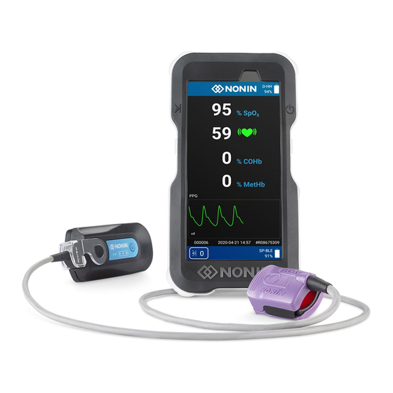
System Components and Set Up System Configuration CO-Pilot System in Carry Case with Finger clip sensor attached Figure 6. System Set Up System Display The system display allows the user to view %COHb, %MetHb, %SpO , and pulse rate data. See below for display features and descriptions. For cleaning instructions, refer to "Care and Maintenance"... -
Page 26: Figure 7. D-Hh Display
System Components and Set Up Figure 7. D-HH Display Table 4. D-HH Features Description Event Mark Button Single Press: Places an event mark with the indicated number into the data file. Hold Press: Creates a new data file for the current session. On/Off,Sleep Button •... -
Page 27: Signal Processor (Sp-Ble)
System Components and Set Up Signal Processor (SP-BLE) The signal processor calculates all measurements and sends to paired display through a Bluetooth Low Energy (BLE) wireless connection. Signal processor requires a sensor to be connected to the sensor connection port to take a measurement. See "Connect/Disconnect a Sensor to the Signal Processor"... -
Page 28: Figure 9. Connect Sensor To Signal Processor
System Components and Set Up Connect/Disconnect a Sensor to the Signal Processor To connect: a. Flip the clear lock on the signal processor back to expose the connection port (Figure 9.A). b. Insert the sensor connector into the signal processor connection port (Figure 9.B). -
Page 29: Sensors
System Components and Set Up Gently spread the lock hinge so it fits over the end of the signal processor. Click the lock into place (Figure 10.B). Figure 10. Signal Processor Lock Replacement Sensors Detailed information regarding specific sensor use (e.g., patient population, body/tissue, application, connecting the sensor to the system) can be found in the respective sensor instructions for use. -
Page 30: System Operation
System Operation System Operation CAUTION: Between patients, start a new patient record. This can be accomplished either by placing the CO-Pilot System into Sleep Mode or by pressing and holding the event mark button. WARNING: This device is intended only as an adjunct device in patient assessment. -
Page 31: Taking A Measurement
System Operation Once display has connected to signal processor, measurement screen will display. The system is now ready to take a measurement. NOTE: If the sensor does not turn on, ensure sensor is plugged into the signal processor. If the sensor still does not turn on, press and hold down the On/Off, Sleep button on the signal processor. -
Page 32: Event Marking
System Operation Event Marking NOTE: New patient record can be started when the event mark button is held for more than 0.5 seconds. Between patients, turn the display off. When the device is turned on, the display begins a new patient record. After turning on the system and applying the sensor to the patient: Press the event mark button to place an event mark in the recorded data Verify the event mark on screen increased by ‘1’. -
Page 33: Charging The System
°C (32 degrees °F) will decrease battery life. Do not charge signal processor at temperatures below 0 °C (32 °F). Display and signal processor must both be charged to use system. Charge the display and signal processor using the provided Nonin chargers. Insert charger into respective display and signal processor charging ports. -
Page 34: Signal Processor Battery Status: Discharge
System Operation Signal Processor Battery Status: Discharge To check battery status on signal processor, Quickly press the On/Off button on signal processor. Battery indicator lights will light indicating current battery status. SP-BLE Battery Indication Battery Level 3 green lights are lit High (60-100%) 2 green lights are lit Medium (20-59%) -
Page 35: Figure 13. Start-Up Screen - Select Transfer Icon
System Operation On display start-up screen tap the file transfer icon to start the data download process as shown below. File transfer icon Figure 13. Start-Up Screen - Select Transfer Icon NOTE: If using the same USB memory stick, the display may automatically return to the file location used for the last data download. -
Page 36: Figure 15. Data Download Screen 2- Memory Stick Location
System Operation Select memory stick location by selecting the USB memory stick in menu: Locate and select the USB symbol icon to store data on memory stick. Figure 15. Data Download Screen 2- Memory Stick Location Choose the desired storage location and press SELECT. Data download will begin automatically once files are selected: Press the SELECT button to store all... -
Page 37: Figure 17. Data Transfer Successful
System Operation Figure 17. Data Transfer Successful... -
Page 38: Figure 18. Download Data Files
System Operation To view downloaded files: Disconnect memory stick from data download cable. Connect memory stick to computer USB port. Open desired file using Microsoft Excel: Figure 18. Download Data Files... -
Page 39: Data Delete
System Operation Data Delete Session data can be deleted from the D-HH device by following the steps below. On display start-up screen tap the File Delete icon to start the data delete process as shown below. Tap the File Delete icon. -
Page 40: Figure 20. Start-Up Screen - Select File Delete Confirm Icon
System Operation Figure 20. Start-Up Screen - Select File Delete Confirm icon Pressing the ‘Check Mark’ icon will delete all files on the D-HH device and pressing the ‘X’ will return to the previous screen (Start-Up Screen - Select File Delete Icon). NOTE: Once files have been deleted, they cannot be recovered. -
Page 41: Setting Date And Time
System Operation Setting Date and Time Date and time must be set manually. To set data and time: Turn on the display to show Start-Up screen. Tap the date and time button. From the Start-Up screen, press the Date and Time button to set date and time Figure 21. -
Page 42: Figure 22. Date And Time Screen - Settings
System Operation Select: • Manually set the date. • Manually set the time. Make sure the following are set: • Automatic = OFF • Automatic time zone = disabled NOTE: The display is not a mobile device; there is no way for display to use automatic time zone. -
Page 43: Care And Maintenance
Care and Maintenance Care and Maintenance The advanced digital circuitry within the CO-Pilot system components requires no calibration or periodic maintenance. Do not attempt to open the case of any of the system components or repair the electronics. Opening the case will damage the component and void the warranty. - Page 44 Care and Maintenance • Clean with a mild detergent (see note) in warm water. Allow to air dry. Do not machine wash or dry. NOTE: To clean washable surfaces, use in a solution of warm water and detergent. Mild detergents, such as hand and dish-washing liquid detergents, dissolve dirt and grease.
-
Page 45: Parts And Accessories
WARNING: Use the CO-Pilot only with charger supplied by Nonin Medical. For more information about Nonin parts and accessories, visit www.nonin.com or contact Nonin at (800) 356-8874 (USA and Canada), +1 (763) 533-9968, or +31 (0)13 - 79 99 040 (Europe). -
Page 46: Compatible Sensors
Parts and Accessories Compatible Sensors The following Nonin sensors are compatible for use with the CO-Pilot System. Model Description Reusable, Finger Clip Pulse Oximeter Sensor 8100AA: Measures SpO2 and pulse rate of adult and pediatric patients (> 30 kg /66 lb) who are well or poorly 8100A Series perfused, during both motion and non-motion conditions. - Page 47 Parts and Accessories List may or will result in increased electromagnetic emission and/or decreased immunity of this device. WARNING: Use only Nonin-branded oximeter sensors. These sensors are manufactured to meet the accuracy specifications for Nonin oximeters. Using other manufacturers’ sensors can result in improper oximeter...
-
Page 48: Troubleshooting
Contact Nonin if signal processor is charged and turned on and an error persists. Connect new sensor to signal Sensor Fault processor Inadequate Signal. - Page 49 Device is not charging. the power supply plug is fully inserted If these solutions do not correct the problem, please contact Nonin Technical Service at (800) 356-8874 (USA and Canada), +1 (763) 553-9968, or +31 (0)13 - 79 99 040 (Europe).
-
Page 50: Error Codes
COM-03 Wireless connection failed Attempt connection again. If security authentication. problem persists, contact Nonin. OXI-01 SP-BLE is not sending Attempt connection again. critical data. Power the device off and then on. If problem persists, contact Nonin. -
Page 51: Service, Support, And Warranty
Service, Support, and Warranty Service, Support, and Warranty Service and Support A return authorization number is required before returning any product to Nonin. To obtain this return authorization number, contact Nonin Technical Service: Nonin Medical, Inc. 13700 1st Avenue North... -
Page 52: Technical Information
Technical Information Technical Information NOTE: This product complies with ISO 10993, Biological Evaluation of Medical Devices Part 1: Evaluation and Testing. CAUTION: A functional tester cannot be used to assess the accuracy of the display, signal processor or sensor. CAUTION: Portable and mobile RF communications equipment can affect medical electrical equipment. -
Page 53: Table 6. Electromagnetic Emissions
Technical Information Table 6. Electromagnetic Emissions Electromagnetic Environment— Emissions Test Compliance Guidance This device is intended for use in the electromagnetic environment specified below. The customer and/or user of this device should ensure that it is used in such an environment. This device must emit electromagnetic RF Emissions energy in order to perform its intended... -
Page 54: Table 7. Electromagnetic Immunity
Technical Information Table 7. Electromagnetic Immunity IEC 60601 Test Compliance Electromagnetic Immunity Test Level Level Environment—Guidance This device is intended for use in the electromagnetic environment specified below. The customer and/or user of this device should ensure that it is used in such an environment. Floors should be wood, concrete, Electrostatic ±6 kV... -
Page 55: Table 8. Guidance And Manufacturer's Declaration-Electromagnetic Immunity
Technical Information Table 8. Guidance and Manufacturer’s Declaration— Electromagnetic Immunity Immunity IEC 60601 Compliance Electromagnetic Test Test Level Level Environment—Guidance This device is intended for use in the electromagnetic environment specified below. The user of this device should ensure that it is used in such an environment. Portable and mobile RF communications equipment should be used no closer to any part of the device, including cables, than the recommended separation distance calculated from the equation applicable to the frequency of the transmitter. - Page 56 Technical Information a. Field strengths from fixed transmitters, such as base stations for radio (cellular/ cordless) telephones and land mobile radios, amateur radio, AM and FM radio broadcast and TV broadcast cannot be predicted theoretically with accuracy. To assess the electromagnetic environment due to fixed RF transmitters, an electromagnetic site survey should be considered.
-
Page 57: Table 9. Recommended Separation Distances
Technical Information Table 9. Recommended Separation Distances This table details the recommended separation distances between portable and mobile RF communications equipment and this device. This device is intended for use in an electromagnetic environment in which radiated RF disturbances are controlled. Users of this device can help prevent electromagnetic interference by maintaining a minimum distance between portable and mobile RF communication equipment (transmitters) and the device as recommended below, according to maximum output power of the... -
Page 58: Equipment Response Time
Technical Information Equipment Response Time If the SpO signal from the sensor is inadequate, the last measured values freeze for 10 seconds and are then replaced with dashes. Values Response Latency Fast Averaged SpO 3 second or faster exponential time constant 2 beats Pulse Rate Values Response... -
Page 59: Testing Summary
There are no adjustable parts within the oximeter that affect the calibration. Nonin oximeters are calibrated to closely approximate functional oxygen saturation, COHb fraction, and MetHb fraction values. -
Page 60: Spo 2 Principles Of Operation
Technical Information Principles of Operation Pulse oximetry is a non-invasive method that passes red and infrared light through perfused tissue and detects the fluctuating signals caused by arterial pulses. Well-oxygenated blood is bright red, while poorly oxygenated blood is dark red. The pulse oximeter determines functional oxygen saturation of arterial hemoglobin (SpO ) from this color difference by measuring the ratio of absorbed red and infrared light as the volume fluctuates with each pulse. -
Page 61: Low Perfusion Accuracy Testing
Technical Information Low Perfusion Accuracy Testing This test uses an SpO Simulator to provide a simulated pulse rate, with adjustable amplitude settings at various SpO levels for the oximeter to read. The oximeter must maintain accuracy in accordance with ISO 80601-2-61 for pulse rate and SpO at the lowest obtainable pulse amplitude (0.3% modulation). -
Page 62: Specifications
Technical Information Specifications CAUTION: The device has been designed for use within the specified ranges. Use outside of these ranges has not been tested and may result in improper oximeter performance. %COHb Display Range: 0 to 99% %MetHb Display Range: 0 to 99% %SpO Display Ranges: 0 to 100% %rSO... - Page 63 Technical Information Power Requirements (Mains): 100–240 VAC 50–60 Hz Internal Power: D-HH Battery: 3.8 volt Li-ion battery, 3600 mAh SP-BLE Battery: 3.7 volt Li-ion battery, 1260 mAh Battery Capacity*: Approximately 10 hours continuous operation *From a fully charged new battery measuring SpO2, PR, COHb, and MetHb.
-
Page 64: Bluetooth Low Energy
Technical Information Classification per IEC 60601-1 / CAN/CSA-C22.2 No. 601.1 / UL60601-1: Type of Protection: Internally powered (on battery power). Class II with AC adapter. Mode of Operation: Continuous Enclosure Degree of Ingress Protection: D-HH, SP-BLE: IP33 Bluetooth Low Energy Overview Bluetooth Low Energy technology allows wireless communication between electronic devices. -
Page 65: Security
Technical Information If encountering a communication disruption, first ensure that the display and signal processor are within their specified operating distance. Then, reposition the devices to minimize the obstructions between them while also separating the devices from nearby obstructions such as solid walls, floors, etc. Interference from nearby wireless devices can also cause communication disruptions. - Page 66 Technical Information THIS PAGE INTENTIONALLY LEFT BLANK...
- Page 67 Technical Information THIS PAGE INTENTIONALLY LEFT BLANK...
Need help?
Do you have a question about the CO-Pilot H500 and is the answer not in the manual?
Questions and answers