Advertisement
2 0 0 5 - 2 0 0 7 K T M S u p e r d u k e
Parts List
1
Power Commander
1
USB Cable
1
CD-ROM
1
Installation Guide
1
Power Adapter
2
Power Commander Decals
2
Dynojet Decals
2
Velcro
Strip
®
1
Alcohol Swab
2
Dynojet O2 eliminators
The ignition MUST be turned
OFF before installation!
You can also download the Power
Commander software and latest maps
from our web site at:
www.powercommander.com
PLEASE READ ALL DIRECTIONS BEFORE STARTING INSTALLATION
Dynojet Research 2191 Mendenhall Drive North Las Vegas, NV 89081 (800) 992-4993 www.powercommander.com
i925-411
www.powercommander.com
I n s ta l l a t i o n I n s t r u c t i o n s
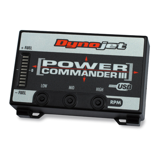
Button Adjustment Display
Faceplate Buttons
Expansion Port
USB Port
2005-2007 KTM Superduke - PCIII USB - 1
Advertisement
Table of Contents

Related Manuals for Dynojet POWER COMMANDER III


Summary of Contents for Dynojet POWER COMMANDER III
- Page 1 Commander software and latest maps from our web site at: www.powercommander.com PLEASE READ ALL DIRECTIONS BEFORE STARTING INSTALLATION Dynojet Research 2191 Mendenhall Drive North Las Vegas, NV 89081 (800) 992-4993 www.powercommander.com i925-411 www.powercommander.com 2005-2007 KTM Superduke - PCIII USB - 1...
- Page 2 Remove screw Remove the main seat. Prop the front of the fuel tank up. Install the PCIII in the tail section on top of the tool kit (Fig. A).. Route the PCIII harness along the right hand side of the bike. Remove the screw securing the tail section to the subframe so that the PCIII harness can be routed underneath the tab (Fig.
- Page 3 Route the PCIII harness between the air box PCIII harness and the frame. Note: This is a very tight fit. The harness can be routed on the outside of the frame if desired. Unplug the stock wiring harness from the injectors (Fig.
- Page 4 Ground wire Route the PCIII ground wire around the front of the engine (Fig. G). Using the supplied zip ties attach the PCIII ground wire to the stock hose. Remove bolts Remove the battery cover by removing the two bolts (Fig. H). Attach the PCIII ground wire to the negative side of the battery (Fig.
- Page 5 If you can not find this connection follow the wires coming out of the exhaust and follow them to the main wiring harness. Plug one of the Dynojet O2 eliminators into the stock wiring harness. The stock O2 sensor will not be connected at Unplug this time.
Need help?
Do you have a question about the POWER COMMANDER III and is the answer not in the manual?
Questions and answers