
Related Manuals for WAGO 750-606/040-000


Summary of Contents for WAGO 750-606/040-000
- Page 1 Manual WAGO I/O SYSTEM 750 XTR 750-606/040-000 Power Supply 24 VDC XTR for Ex i XTR Modules Supply module; 24 VDC; Extreme, For Intrinsically Safe XTR Modules Version 2.0.0...
- Page 2 WAGO I/O SYSTEM 750 XTR 750-606/040-000 Power Supply 24 VDC XTR for Ex i XTR Modules © 2019 WAGO Kontakttechnik GmbH & Co. KG All rights reserved. WAGO Kontakttechnik GmbH & Co. KG Hansastraße 27 D-32423 Minden +49 (0) 571/8 87 – 0 Phone: +49 (0) 571/8 87 –...
-
Page 3: Table Of Contents
WAGO I/O SYSTEM 750 XTR Table of Contents 750-606/040-000 Power Supply 24 VDC XTR for Ex i XTR Modules Table of Contents Notes about this Documentation ............. 5 Validity of this Documentation..............5 Copyright ....................5 Symbols ....................6 Number Notation ..................8 Font Conventions ................... - Page 4 Table of Contents WAGO I/O SYSTEM 750 XTR 750-606/040-000 Power Supply 24 VDC XTR for Ex i XTR Modules Power Supply Concept ................. 41 6.2.1 Supplementary Power Supply Regulations ........44 6.2.2 Power Supply Units ................47 Use in Hazardous Environments ............48 Marking Configuration Examples ............
-
Page 5: Notes About This Documentation
(Power Supply 24 VDC XTR for Ex i XTR Modules). The I/O module 750-606/040-000 shall only be installed and operated according to the instructions in this manual, in the system description for the WAGO I/O SYSTEM 750 XTR and in the manual for the used fieldbus coupler/controller. -
Page 6: Symbols
Notes about this Documentation WAGO I/O SYSTEM 750 XTR 750-606/040-000 Power Supply 24 VDC XTR for Ex i XTR Modules Symbols Personal Injury! Indicates a high-risk, imminently hazardous situation which, if not avoided, will result in death or serious injury. - Page 7 WAGO I/O SYSTEM 750 XTR Notes about this Documentation 750-606/040-000 Power Supply 24 VDC XTR for Ex i XTR Modules Additional Information: Refers to additional information which is not an integral part of this documentation (e.g., the Internet). Manual Version 2.0.0...
-
Page 8: Number Notation
Notes about this Documentation WAGO I/O SYSTEM 750 XTR 750-606/040-000 Power Supply 24 VDC XTR for Ex i XTR Modules Number Notation Table 1: Number Notation Number Code Example Note Decimal Normal notation Hexadecimal 0x64 C notation Binary '100' In quotation marks, nibble separated '0110.0100'... -
Page 9: Important Notes
2.1.1 Subject to Changes WAGO Kontakttechnik GmbH & Co. KG reserves the right to provide for any alterations or modifications. WAGO Kontakttechnik GmbH & Co. KG owns all rights arising from the granting of patents or from the legal protection of utility patents. -
Page 10: Technical Condition Of Specified Devices
These modules contain no parts that can be serviced or repaired by the user. The following actions will result in the exclusion of liability on the part of WAGO Kontakttechnik GmbH & Co. KG: •... -
Page 11: 2.1.4.1.2 Packaging
WAGO I/O SYSTEM 750 XTR Important Notes 750-606/040-000 Power Supply 24 VDC XTR for Ex i XTR Modules • Observe national and local regulations for the disposal of electrical and electronic equipment. • Clear any data stored on the electrical and electronic equipment. -
Page 12: Safety Advice (Precautions)
Important Notes WAGO I/O SYSTEM 750 XTR 750-606/040-000 Power Supply 24 VDC XTR for Ex i XTR Modules Safety Advice (Precautions) For installing and operating purposes of the relevant device to your system the following safety precautions shall be observed:... - Page 13 WAGO I/O SYSTEM 750 XTR Important Notes 750-606/040-000 Power Supply 24 VDC XTR for Ex i XTR Modules Power from SELV/PELV power supply only! All field signals and field supplies connected to this XTR I/O module (750-606/040-000) must be powered from SELV/PELV power supply(s)! Do not touch hot surfaces! The surface of the housing can become hot during operation.
- Page 14 Important Notes WAGO I/O SYSTEM 750 XTR 750-606/040-000 Power Supply 24 VDC XTR for Ex i XTR Modules Do not reverse the polarity of connection lines! Avoid reverse polarity of data and power supply lines, as this may damage the devices involved.
-
Page 15: Device Description
750-606/040-000 Power Supply 24 VDC XTR for Ex i XTR Modules Device Description The I/O module 750-606/040-000 (Power Supply 24 VDC XTR for Ex i XTR Modules) provides 24 VDC power to the 750 XTR Series. Furthermore, it separates the intrinsically safe part from the non-intrinsically safe part of the fieldbus node and makes diagnostic information available in the process image. - Page 16 Device Description WAGO I/O SYSTEM 750 XTR 750-606/040-000 Power Supply 24 VDC XTR for Ex i XTR Modules The I/O module can be operated with all fieldbus couplers/controllers of the WAGO I/O SYSTEM 750 XTR. Observe the instructions for mixed operation when used in mixed operation behind standard fieldbus couplers/controllers.
-
Page 17: View
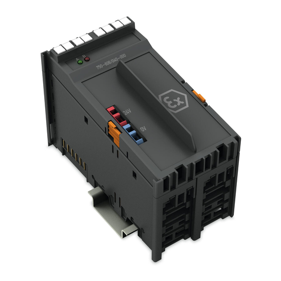
WAGO I/O SYSTEM 750 XTR Device Description 750-606/040-000 Power Supply 24 VDC XTR for Ex i XTR Modules View Figure 1: View </dg_ Table 3: Legend for Figure “View” No. Explanation For details, see Section Marking possibility with Mini- “Device Description” > “Display Status LEDs Elements”... -
Page 18: Connectors
Device Description WAGO I/O SYSTEM 750 XTR 750-606/040-000 Power Supply 24 VDC XTR for Ex i XTR Modules Connectors 3.2.1 Data Contacts/Local Bus Communication between the fieldbus coupler/controller and the I/O modules as well as the system supply of the I/O modules is carried out via the local bus. The contacting for the local bus consists of 6 data contacts, which are available as self-cleaning gold spring contacts. -
Page 19: Power Jumper Contacts/Field Supply
Do not exceed maximum current via power contacts! The maximum current available from the “Power Supply 24 VDC Diagn for Ex i XTR Modules” 750-606/040-000 is 1 A. Greater currents can damage the power contacts. When configuring the system, ensure that this current is not exceeded. -
Page 20: Cage Clamp
Device Description WAGO I/O SYSTEM 750 XTR 750-606/040-000 Power Supply 24 VDC XTR for Ex i XTR Modules ® 3.2.3 CAGE CLAMP Connectors ® Figure 4: CAGE CLAMP Connectors ® Table 5: Legend for Figure “CAGE CLAMP Connectors” Designation Connector Function... -
Page 21: Display Elements
WAGO I/O SYSTEM 750 XTR Device Description 750-606/040-000 Power Supply 24 VDC XTR for Ex i XTR Modules Display Elements Figure 5: Display Elements Table 6: Legend for Figure “Display Elements” Designation LED State Function No power supply at the infeed input Power supply status –... -
Page 22: Schematic Diagram
Device Description WAGO I/O SYSTEM 750 XTR 750-606/040-000 Power Supply 24 VDC XTR for Ex i XTR Modules Schematic Diagram Figure 6: Schematic Diagram Manual Version 2.0.0... -
Page 23: Technical Data
WAGO I/O SYSTEM 750 XTR Device Description 750-606/040-000 Power Supply 24 VDC XTR for Ex i XTR Modules Technical Data 3.6.1 Device Data Table 7: Technical Data – Device Width 48 mm Height (from upper edge of DIN-rail) 63.7 mm... -
Page 24: Power Supply
Device Description WAGO I/O SYSTEM 750 XTR 750-606/040-000 Power Supply 24 VDC XTR for Ex i XTR Modules 3.6.2 Power Supply Table 8: Technical Data – Power Supply Current consumption, system voltage 7.5 mA max. Input voltage 24 VDC (power supply via SELV/ PELV power supply unit) 18 V …... -
Page 25: Explosion Protection
WAGO I/O SYSTEM 750 XTR Device Description 750-606/040-000 Power Supply 24 VDC XTR for Ex i XTR Modules 3.6.3 Explosion Protection Table 9: Technical Data – Explosion Protection = 24 VDC (−10 % … +10 %); Power supply, input = 29 W;... -
Page 26: Climatic Environmental Conditions
Device Description WAGO I/O SYSTEM 750 XTR 750-606/040-000 Power Supply 24 VDC XTR for Ex i XTR Modules 3.6.7 Climatic Environmental Conditions Table 15: Technical Data ‒ Climatic Environmental Conditions −40 °C … +70 °C Surrounding air temperature, operation −40 °C … +85 °C... -
Page 27: Approvals
WAGO I/O SYSTEM 750 XTR Device Description 750-606/040-000 Power Supply 24 VDC XTR for Ex i XTR Modules Approvals The following approvals were granted for the 750-606/040-000 I/O module: Conformity Marking UL61010-2-201 The following approvals are pending for the 750-606/040-000 I/O module:... - Page 28 PRS (Polski Rejestr Statków) More information about approvals. Detailed references to the approvals are listed in the document “Overview Approvals WAGO I/O SYSTEM 750”, which you can find via the internet under: DOWNLOADS Documentation System Description. www.wago.com Manual Version 2.0.0...
-
Page 29: Standards And Guidelines
WAGO I/O SYSTEM 750 XTR Device Description 750-606/040-000 Power Supply 24 VDC XTR for Ex i XTR Modules Standards and Guidelines 750-606/040-000 I/O modules meet the following standards and guidelines: Table 16: Standards and Rated Conditions for Explosion Protection Applications ATEX acc. -
Page 30: Table 17: Climatic And Mechanical Environmental Conditions And Shipbuilding
Device Description WAGO I/O SYSTEM 750 XTR 750-606/040-000 Power Supply 24 VDC XTR for Ex i XTR Modules Table 17: Climatic and Mechanical Environmental Conditions and Shipbuilding Standard Test Value Transport EN 60870-2-2 Ct2(2k4) (except precipitation/water/moisture) Mechanical Environmental Conditions EN 61850-3... -
Page 31: Table 18: Emc - Immunity To Interference
WAGO I/O SYSTEM 750 XTR Device Description 750-606/040-000 Power Supply 24 VDC XTR for Ex i XTR Modules The I/O module 750-606/040-000 meets the following EMC standards as these standards relate to the I/O module: Table 18: EMC – Immunity to Interference... - Page 32 Device Description WAGO I/O SYSTEM 750 XTR 750-606/040-000 Power Supply 24 VDC XTR for Ex i XTR Modules Table 18: EMC – Immunity to Interference Standard Test Value Damped Oscillatory Waves • EN 61000-4-18 1.25 kV conductor/conductor • EN 60255-26 2.5 kV conductor/ground...
-
Page 33: Table 19: Emc - Emission Of Interference
WAGO I/O SYSTEM 750 XTR Device Description 750-606/040-000 Power Supply 24 VDC XTR for Ex i XTR Modules Table 19: EMC – Emission of Interference Standard Test Value Enclosure Emission of Interference • EN 61000-6-3 30 dB(µV/m), QP, 30 MHz … 230 MHz •... -
Page 34: Table 20: Standards And Rated Conditions For Rail Applications (En 50155)
Device Description WAGO I/O SYSTEM 750 XTR 750-606/040-000 Power Supply 24 VDC XTR for Ex i XTR Modules Table 19: EMC – Emission of Interference Standard Test Value Conducted Emission of Interference – Line Connection DC Voltage • EN 61000-6-3 79 dB(µV) QP, 0.15 MHz …... -
Page 35: Process Image
WAGO I/O SYSTEM 750 XTR Process Image 750-606/040-000 Power Supply 24 VDC XTR for Ex i XTR Modules Process Image Mapping of process data in the process image of fieldbus systems The representation of the I/O modules’ process data in the process image depends on the fieldbus coupler/controller used. -
Page 36: Mounting
Mounting WAGO I/O SYSTEM 750 XTR 750-606/040-000 Power Supply 24 VDC XTR for Ex i XTR Modules Mounting Mounting Sequence Fieldbus couplers, controllers and I/O modules of the WAGO I/O SYSTEM 750 are snapped directly on a carrier rail in accordance with the European standard EN 60175 (DIN 35). -
Page 37: Inserting And Removing Devices
WAGO I/O SYSTEM 750 XTR Mounting 750-606/040-000 Power Supply 24 VDC XTR for Ex i XTR Modules Inserting and Removing Devices Do not touch hot surfaces! The surface of the housing can become hot during operation. If the device was operated at high ambient temperatures, allow it to cool off before touching it. -
Page 38: Figure 9: Snap The I/O Module Into Place (Example)
Mounting WAGO I/O SYSTEM 750 XTR 750-606/040-000 Power Supply 24 VDC XTR for Ex i XTR Modules Press the I/O module into the assembly until the I/O module snaps into the carrier rail. Figure 9: Snap the I/O Module into Place (Example) -
Page 39: Removing The Power Supply Module
WAGO I/O SYSTEM 750 XTR Mounting 750-606/040-000 Power Supply 24 VDC XTR for Ex i XTR Modules 5.2.2 Removing the Power Supply Module The power supply module has 2 release tabs. To remove the power supply module, pull it out of the unit on both release tabs. -
Page 40: Connect Devices
Connect Devices WAGO I/O SYSTEM 750 XTR 750-606/040-000 Power Supply 24 VDC XTR for Ex i XTR Modules Connect Devices ® Connecting a Conductor to the CAGE CLAMP ® The WAGO CAGE CLAMP connection is appropriate for solid, stranded and finely stranded conductors. -
Page 41: Power Supply Concept
The maximum current available from the 750-606/040-000 “Power Supply 24 VDC Diagn for Ex i XTR Modules” is 1 A. If the use of further 750-606/040-000 is necessary for reasons of extent of utilization, 4 Separation Modules (750-616/040-000) must be used to guarantee the distance between the intrinsically safe segments. -
Page 42: Figure 12: Ex I Xtr Power Supply Concept
Connect Devices WAGO I/O SYSTEM 750 XTR 750-606/040-000 Power Supply 24 VDC XTR for Ex i XTR Modules Figure 12: Ex i XTR Power Supply Concept Table 22: Legend for Figure “Ex i XTR Power Supply Concept” Pos. Explanation XTR fieldbus coupler / controller XTR I/O modules XTR supply „Power Supply 24 VDC Diagn for Ex i XTR Modules“... -
Page 43: Figure 13: Overvoltage Categories
WAGO I/O SYSTEM 750 XTR Connect Devices 750-606/040-000 Power Supply 24 VDC XTR for Ex i XTR Modules Figure 13: Overvoltage Categories Table 23: Legend for Figure “Overvoltage Categories” Pos. Explanation XTR fieldbus coupler/controller XTR filter module XTR supply module “Power Supply 24 VDC Diagn for Ex i XTR Modules”... -
Page 44: Supplementary Power Supply Regulations
6.2.1 Supplementary Power Supply Regulations The WAGO I/O SYSTEM 750 XTR can also be used in shipbuilding applications and onshore/offshore installations (e.g., platforms, loading facilities), as well as in the rail sector and telecontrol applications. This is possible via certification under the standards of leading agencies such as DNV GL and Lloyds Register. -
Page 45: Figure 14: Power Supply Concept, Example 1
WAGO I/O SYSTEM 750 XTR Connect Devices 750-606/040-000 Power Supply 24 VDC XTR for Ex i XTR Modules Figure 14: Power Supply Concept, Example 1 Table 25: Legend for Figure “Power Supply Concept, Example 1” Pos. Explanation XTR fieldbus coupler / controller XTR filter module 750-626/040-000 XTR supply “Power Supply 24 VDC Diagn for Ex i XTR Modules”... -
Page 46: Figure 15: Power Supply Concept, Example 2
Table 26: Legend for Figure “Power Supply Concept, Example 2“ Pos. Explanation XTR fieldbus coupler / controller XTR filter module 750-626/040-000 XTR filter module (750-626/040-000 or 750-624/040-001) XTR supply 750-606/040-000 “Power Supply 24 VDC Diagn for Ex i XTR Modules” I/O modules Ex i XTR XTR end module Manual... -
Page 47: Power Supply Units
750-606/040-000 Power Supply 24 VDC XTR for Ex i XTR Modules 6.2.2 Power Supply Units The WAGO I/O SYSTEM 750 XTR requires 24 VDC voltage (system supply) for operation. Recommendation A stable power supply cannot always be assumed everywhere. Therefore, you should use regulated power supplies to ensure the quality of the supply voltage (see also table “WAGO power supply units”). -
Page 48: Use In Hazardous Environments
750-606/040-000 Power Supply 24 VDC XTR for Ex i XTR Modules Use in Hazardous Environments The WAGO I/O SYSTEM 750 (electrical equipment) is designed for use in Zone 2 hazardous areas and shall be used in accordance with the marking and installation regulations. -
Page 49: Marking Configuration Examples
WAGO I/O SYSTEM 750 XTR Use in Hazardous Environments 750-606/040-000 Power Supply 24 VDC XTR for Ex i XTR Modules Marking Configuration Examples 7.1.1 Marking for Europe According to ATEX and IECEx Figure 16: Marking Example According to ATEX and IECEx Figure 17: Text Detail –... -
Page 50: Table 27: Description Of Marking Example According To Atex And Iecex
Use in Hazardous Environments WAGO I/O SYSTEM 750 XTR 750-606/040-000 Power Supply 24 VDC XTR for Ex i XTR Modules Table 27: Description of Marking Example According to ATEX and IECEx Marking Description TUEV 07 ATEX 554086 X Approving authority resp. certificate numbers IECEx TUN 09.0001 X... -
Page 51: Figure 18: Marking Example For Approved Ex I I/O Module According To Atex And Iecex
WAGO I/O SYSTEM 750 XTR Use in Hazardous Environments 750-606/040-000 Power Supply 24 VDC XTR for Ex i XTR Modules Figure 18: Marking Example for Approved Ex i I/O Module According to ATEX and IECEx Figure 19: Text Detail – Marking Example for Approved Ex i I/O Module According to ATEX and... -
Page 52: Table 28: Description Of Marking Example For Approved Ex I I/O Module According To Atex And Iecex
Use in Hazardous Environments WAGO I/O SYSTEM 750 XTR 750-606/040-000 Power Supply 24 VDC XTR for Ex i XTR Modules Table 28: Description of Marking Example for Approved Ex i I/O Module According to ATEX and IECEx Marking Description TUEV 12 ATEX 106032 X Approving authority resp. -
Page 53: Marking For The United States Of America (Nec) And Canada (Cec)
WAGO I/O SYSTEM 750 XTR Use in Hazardous Environments 750-606/040-000 Power Supply 24 VDC XTR for Ex i XTR Modules 7.1.2 Marking for the United States of America (NEC) and Canada (CEC) Figure 20: Marking Example According to NEC Figure 21: Text Detail – Marking Example According to NEC 500... -
Page 54: Figure 22: Text Detail - Marking Example For Approved
Use in Hazardous Environments WAGO I/O SYSTEM 750 XTR 750-606/040-000 Power Supply 24 VDC XTR for Ex i XTR Modules Figure 22: Text Detail – Marking Example for Approved Ex i I/O Module According to NEC 505 Table 30: Description of Marking Example for Approved Ex i I/O Module According to NEC 505... -
Page 55: Figure 24: Text Detail - Marking Example For Approved
WAGO I/O SYSTEM 750 XTR Use in Hazardous Environments 750-606/040-000 Power Supply 24 VDC XTR for Ex i XTR Modules Figure 24: Text Detail – Marking Example for Approved Ex i I/O Modules According to CEC 18 attachment J Table 32: Description of Marking Example for Approved Ex i I/O Modules According to CEC 18... -
Page 56: Installation Regulations
Use in Hazardous Environments WAGO I/O SYSTEM 750 XTR 750-606/040-000 Power Supply 24 VDC XTR for Ex i XTR Modules Installation Regulations For the installation and operation of electrical equipment in hazardous areas, the valid national and international rules and regulations which are applicable at the installation location must be carefully followed. - Page 57 WAGO I/O SYSTEM 750 XTR Use in Hazardous Environments 750-606/040-000 Power Supply 24 VDC XTR for Ex i XTR Modules Explosive atmosphere occurring simultaneously with assembly, installation or repair work must be ruled out. Among other things, these include the following activities •...
-
Page 58: Special Notes Regarding Ansi/Isa Ex
Use in Hazardous Environments WAGO I/O SYSTEM 750 XTR 750-606/040-000 Power Supply 24 VDC XTR for Ex i XTR Modules 7.2.2 Special Notes Regarding ANSI/ISA Ex For ANSI/ISA Ex acc. to UL File E198726, the following additional requirements apply: •... -
Page 59: List Of Figures
WAGO I/O SYSTEM 750 XTR List of Figures 750-606/040-000 Power Supply 24 VDC XTR for Ex i XTR Modules List of Figures Figure 1: View ....................17 Figure 2: Data Contacts ..................18 Figure 3: Power Jumper Contacts ..............19 ® Figure 4: CAGE CLAMP Connectors ..............20... -
Page 60: List Of Tables
List of Tables WAGO I/O SYSTEM 750 XTR 750-606/040-000 Power Supply 24 VDC XTR for Ex i XTR Modules List of Tables Table 1: Number Notation ................... 8 Table 2: Font Conventions .................. 8 Table 3: Legend for Figure “View” ..............17 Table 4: Legend for Figure “Power Jumper Contacts”... - Page 61 WAGO I/O SYSTEM 750 XTR 750-606/040-000 Power Supply 24 VDC XTR for Ex i XTR Modules Manual Version 2.0.0...
- Page 62 WAGO Kontakttechnik GmbH & Co. KG • Postfach 2880 D - 32385 Minden Hansastraße 27 • D - 32423 Minden +49 571 887 – 0 Phone: +49 571 887 – 844169 Fax: E-Mail: info@wago.com Internet: www.wago.com...
Need help?
Do you have a question about the 750-606/040-000 and is the answer not in the manual?
Questions and answers