
Related Manuals for Riello ALU PRO power Series


Summary of Contents for Riello ALU PRO power Series
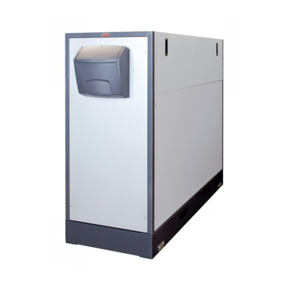
- Page 1 ALUMINIUM CONDENSING BOILERS ALU PRO power INSTRUCTIONS FOR THE INSTALLER AND FOR THE TECHNICAL ASSISTANCE CENTRE...
-
Page 2: Conformity
CONFORMITY ALU PRO Power condensing boilers comply with: • Gas Appliance Directive 2009/142/EC • Efficiency Directive 92/42/EEC and Attachment E of the Pres. Decree 26 August 1993 no. 412 (****) • Electromagnetic Compatibility Directive 2014/30/EU • Ecodesign Directive for energy-related products 2009/125/EC •... - Page 3 This manual provides information that is essential for the proper installation of the appliance. Used in conjunction with your own knowledge and expertise it will enable you to install the appliance quickly, easily, and correctly. Please accept our thanks again on your choice of product Riello S.p.A. GENERAL...
-
Page 4: Table Of Contents
CONTENTS GENERAL Conformity Range Index General Safety Information Basic safety rules Description of the appliance Safety devices Identification Data plate Structure Technical data Accessories Water circuit Pumps Positioning the temperature sensors Wiring diagram Control panel Operation TECHNICAL ASSISTANCE CENTRE INSTALLER Initial commissioning Product delivery Checks during and after initial start-up... -
Page 5: General Safety Information
GENERAL SAFETY INFORMATION After removing the packaging make sure that Periodically check that operating pressure in the water circuit is greater than 1.5 bar and less than everything is there and undamaged, if not contact the r Agency that sold you the appliance. the maximum limit provided for the appliance. -
Page 6: Description Of The Appliance
DESCRIPTION OF THE APPLIANCE The aluminium ALU PRO POWER boilers are modular climate logic, with an outdoor temperature sensor, and it condensing heat generators for heating systems and allows you to regulate the outlet temperature according when used with storage cylinders, for producing domes- to the outside temperature. -
Page 7: Identification
Combustible: Categorie: Brennstoff: Brandstof: Kategorie: RIELLO S.p.A. and the country in which the Via Ing.Pilade Riello 7 37045 Legnago (VR) - ITALY T067746GE Caldaia a condensazione - Chaudière à condensation NOx: European Directive Brennwertkessel - Condenserende verwarmingsketel boiler is destined for use. -
Page 8: Structure
STRUCTURE FRONT view LEFT SIDE view 1 - Control panel 20- Side panel 2 - Control panel 21 - Thermal module safety thermostat 3 - Front panel 22 - Flue gas probe 4 - Base 23 - Flue gas box 5 - Condensate drain 24 - Flue gas analysis outlet 6 - Flue gas thermostat... - Page 9 23 24 RIGHT SIDE view TOP view GENERAL...
- Page 10 Diagram of SETTINGS FOR THE THERMAL MODULES DIP-Switch DIP-Switch DO NOT IMPOSTAZIONE MODE SETTING MODULO MODIFICARE CHANGE Module 1 Modulo 1 Modulo 2 Module 2 Modulo 3 Module 3 Modulo 4 Module 4 Switch Modulo 5 Module 5 Switch Modulo 6 Module 6 Modulo 7 Module 7...
-
Page 11: Technical Data
Electrical protection level with kit for outdoors Boiler net weight (*) Noise levels measured as continuous A-weighted sound pressure, at 1 metre from the appliance. ACCESSORIES For the specific related accessories see the Riello catalogue and the product datasheet. GENERAL... -
Page 12: Water Circuit
WATER CIRCUIT Gas inlet collector Condensate discharge syphon Burner assembly Automatic venting valve Combustion chamber Heat exchange element System flow SR System return Flue gas box Gas Fuel supply Flue gas outlet fitting Boiler filling/draining tap Discharge PUMPS Select a pump that is compatible with the water resistor of the boiler and the system. The illustration below shows the resistor characteristics. -
Page 13: Positioning The Temperature Sensors
POSITIONING THE TEMPERATURE SENSORS RIGHT SIDE view LEFT SIDE view SENSORS INSERTED IN THEIR SOCKETS IN THE BOILER 1 - Return temperature sensor 2 - Thermal module safety thermostat 3 - Thermal module flow sensor 4 - Safety thermostat 5 - Flow sensor 6 - Flue gas probe 7 - Flue gas thermostat GENERAL... -
Page 14: Wiring Diagram
WIRING DIAGRAM Pacqua Pgas Pacqua Pgas SCH1 X1-1/12-x2 0-10 out 0-10 out 0-10 0-10 SCH-SEQ-01 X12-1/12-X2 DISP DISP L N PE Power supply Alimentazione 230V 50Hz PCol 230V 50Hz CONNECTIONS TO BE PROVIDED BY THE INSTALLER COLLEGAMENTI A CURA DELL’INSTALLATORE Main board Main switch SCH1... - Page 15 RS 485 SCH2 SCH9 Da 1 a 8 Moduli From 1 to 8 Modules Tm-TA1 Tm-TA8 Alimentazione Power supply of the modules Moduli Connections to be provided by the installer: PCol Circulator collector (accessory) SM1..8 Flow sensor heating element Circulator storage cylinder (accessory) TS1..8 Safety thermostat heating element Gas shut-off valve (accessory)
-
Page 16: Control Panel
CONTROL PANEL BASIC INFORMATION / INTERFACE COMMANDS CONTROL PANEL IN CLOSED POSITION CONTROL PANEL IN OPEN POSITION - Electrical power indicator (green) - Information button Lights to show that the system is receiving electri- 9-10 - Button for changing parameter value cal power . - Page 17 SECONDARY INFORMATION / DISPLAY VIEW Auto Standby - Large numeric display. Displaying current value, non-volatile errors - Display symbols: v DHW temperature or DHW mode active r CH or room temperature setpoint, or CH mode active c Outdoor temperature o Nominal mode l Reduced mode f Flame present n Error...
- Page 18 MAIN SCREEN Auto Standby A1 - Operating mode. Mode Pressing the " " button, the bar appears under the corresponding mode symbol. B1 - DHW mode. The button " " (above the display) switches the mode on or off. C1 - Nominal operating mode D1 - Time of day E1 - Current boiler temperature - Flame presence...
-
Page 19: Operation
Functional notes The control panel of the ALU PRO power boiler oversees: - The domestic hot water priority function that gives - The over-temperature dispersal function: if for any rea- domestic hot water priority over heating hot water. son the limit temperature C515 is reached, the boiler switches off and the accumulated heat is dispersed - The anti-freeze function: activating the system pump, if the last request was... - Page 20 NIGHT-TIME REDUCTION Strategy A = Simultaneous Ignition/Switching off of all the night-time reduction function is active when all the modules (C604=0) following conditions exist contemporaneously: Strategy B = independent Simultaneous Ignition/ - parameter C806 = 1 (function enable); Switching off (C604=1). - there is an outdoor temperature sensor and it is work- ing;...
- Page 21 ter C609 (P_ACC). After the second module comes on, the overall output requested is divided between the two 1 - If the difference between the setpoint temperature modules. and the temperature of the delivery collector probe is When the two modules that are on reach the output of greater than the parameter C616 (Delta_T for ignition the parameter C609 (P_ACC), a third module is ignited of all the modules with strategy B), then all the mod-...
- Page 22 ADDITIONAL FUNCTIONS With a storage cylinder probe, the anti-legionella function 0-10V output (modulating pump) can be activated (H614) in the following ways: The 0-10V analogue output available on the boiler is used H614 = 0 Anti-legionella disengaged for a rapid control of the system pump that is managed so H614 = 1 Anti-legionella weekly as to maintain the boiler delivery-return delta at the value...
- Page 23 Fuel check valve 5 - Pump anti-block function The control of the ALU PRO power boiler allows you to If the system pump does not operate for 24h, it is started control an external fuel shut-off valve. The function is for 10s (system pump anti-block).
-
Page 24: Product Delivery
PRODUCT DELIVERY The boiler is delivered on a wooden pallet, suitably packed and protected by a wooden crate. Its condition and compli- ance with what was ordered must be checked immediately. The specific characteristics of the product are indicated on the outside: model, power, equipment, fuel type .If there is a discrepancy between what was ordered and what was received, immediately contact the local agent, warehouse... -
Page 25: Dimensions And Weights
DIMENSIONS AND WEIGHTS ALU PRO power 1264 1264 1264 1654 1534,5 1534,5 1534,5 1534,5 Weight ALU PRO power 1654 2103 2103 2298 1534,5 1534,5 1534,5 1534,5 Weight HANDLING Use equipment adequate for the weight involved to move the boiler to the place of installation. Make sure that the boiler does not strike rigid surfac- es like floors or walls when it is being moved. - Page 26 - Remove the brackets at the corners of the base fixing the boiler to the pallet. - Screw the eyebolts (supplied) into their holes, then hook up the lifting belts as shown in the illustration. - Carefully lift the boiler and position it. 60 cm HANDLING WITH A FORK LIFT - Once the fixing brackets have been removed, the boiler...
- Page 27 HANDLING WITH ROLLERS If the route to the installation area is flat, the boiler can be moved with the use of rollers. This requires at least 5 pipes roughly 900 mm long and 1"1/4 in diameter, or else commonly found transport roll- ers can be used.
-
Page 28: Place Of Installation
PLACE OF INSTALLATION The ALU PRO power boilers, since they generate over When installing the boiler, allow sufficient space 35 kW of heat output, MUST be installed in a dedicat- around it to access all safety and control devices and ed boiler room in compliance with applicable technical to permit easy maintenance. -
Page 29: Water In Central Heating Systems
WATER IN CENTRAL HEATING SYSTEMS INTRODUCTION Always comply with the legislation applicable in the It is ABSOLUTELY NECESSARY to treat the water system country of installation. for the heat generator to work properly and to guarantee its service life together with all its components. This not only applies to jobs carried out on existing instal- lations but also on new installations. - Page 30 2. The heating systems Topping up should not be dome using an automatic filling system, but rather done manually and should be recorded in the service book. If there are more than one boiler, they must all be put into service either at the same time or with a very short rotation time so as to evenly distribute the limited quantity of initial lime-scale.
- Page 31 Mistakes to avoid and precautions. From what we have seen it is therefore important to avoid two factors possibly leading to the above mentioned processes i.e. contact between air and water in the installation and regular topping up with fresh water. To eliminate contact between air and water (and to prevent the latter from becoming oxidized), it is necessary: - that the expansion system be a closed vessel, correctly sized and with the correct pre-loading pressure (to be regularly checked);...
-
Page 32: Water Connections
WATER CONNECTIONS The ALU PRO power boilers have been designed and constructed to be installed on central heating systems and, if used with a remote storage cylinder, the production of hot water. Water fittings have the following specifications: ALU 150 - 375 PRO power ALU 115 PRO ALU 150 PRO ALU 225 PRO... - Page 33 ALU 450 - 600 PRO power ALU 450 PRO power ALU 525 PRO power ALU 600 PRO power A (mm) B (mm) C (mm) D (mm) E (mm) 1735 1735 1938 F (mm) 2103 2103 2298 G (mm) Ø H (mm) 1 - Delivery System Flange PN10 DN65 Flange PN10 DN65...
- Page 34 Typical water system schematics Pump of Valvola di Pompa del Non-return valve the radiator non ritorno circuito circuit radiatori Flow Flusso Pompa DHW pump A.C.S. Radiatori Radiators Accumulo A.C.S. Storage Valvola di Non-return non ritorno valve Flusso Filtro Flow Filter Circuito caldaia con pompa A.C.S.
- Page 35 Typical water system schematics Pump of Valvola di Pompa del Non-return valve the radiator non ritorno circuito circuit radiatori Flow Flusso Radiatori Radiators Flusso Filtro Flow Filter Circuito caldaia con un gruppo di radiatori Boiler circuit with a unit of radiators Termostato ambiente del tipo on/off o a modulazione On/off or modulating room thermostat Outlet...
- Page 36 Typical water system schematics Outlet Mandata Radiatori Radiatori Radiators Radiators Filtro Filter Circuito Circuito Radiator Radiator radiatore pompa radiatore pompa circuit pump circuit pump Circuito caldaia con più gruppi di radiatori. Boiler circuit with several radiator units. Sensore esterno e controllo preliminare della temperatura di mandata della caldaia. Outdoor sensor and preliminary control of the delivery temperature of the boiler.
-
Page 37: Draining The Condensate
DRAINING THE CONDENSATE Condensate drainage systems must be: - made in such a way as to prevent the leakage of flue and combustion gases into the environment or the sewer system (siphon required) - of the right size and type to ensure the proper drainage of waste liquids without leakage - installed in such a way as to prevent the freezing of the liquid inside under normal operating conditions - mixed for example with domestic waste liquids (from washing machines, dishwashers, etc.) mostly with a standard pH so as to form a buffer solution that can be put in the sewers. -
Page 38: Condensate Neutraliser
CONDENSATE NEUTRALISER TYPE N2 NEUTRALISATION UNIT The TYPE N2 neutralisation unit was designed for systems equipped with the central heating plant condensate outlet trap located lower than the boiler condensate outlet. This neutralisation kits does not require electric connections. Type Qt y. - Page 39 The inlet fitting (A) of the N2 neutralisation unit (the lower fitting) must be connected to the boiler condensate drain using the flexible hose (C) supplied with the unit. This con- densate drain hose is specially made to prevent combustion fumes escaping into the atmosphere.
-
Page 40: Gas Connection
GAS CONNECTION ALU 115 ÷ 375 PRO power ALU 450 - 600 PRO power ALU 115 - 375 PRO power ALU 450 - 600 PRO power ALU 115 ALU 150 ALU 225 ALU 300 ALU 450 ALU 525 ALU 600 349-375 power power... -
Page 41: System Anti-Freeze Protection
SYSTEM ANTI-FREEZE PROTECTION The ALU PRO power condensing boilers are fitted with electronics that provide protection against frost. The electronics activate the heating unit if the temperature drops below the minimum threshold. No special anti-frost additives are therefore needed, unless the system is to be completely shut down for an extended period of time. -
Page 42: Electrical Wiring
ELECTRICAL WIRING The ALU PRO power condensing boilers leave the factory completely cabled. There remain only the connections to the electrical supply, to the room thermostat and to the outdoor temperature sensor. For the connections to any other devices (accessories) see the diagram on the following page. Proceed as follows to access the control panel terminals: - Turn the small panel (1), unscrew the two screws (2) and remove the cover (3). - Page 43 Collegare solo pompe Connect only pumps with a con un assorbimento maximum energy absorption elettrico massimo equal to or less than 1A inferiore o uguale a 1A Central heating pump Pompa Impianto Storage cylinder pump Central heating Pompa Bollitore Pompa Impianto Gas valve pump Valvola gas...
- Page 44 it is mandatory to: It is prohibited to use gas and/or water pipes for 1 - to use an omnipolar cut-off switch, a line dis- earthing the appliance. connecting switch, in compliance with CEI-EN standards (contact opening of at least 3 mm); It is prohibited to pass the power supply and room 2 - to respect the connection L1 (Phase) - N (Neutral) thermostat cables near hot surfaces (delivery pipes).
-
Page 45: Connecting The Outdoor Temperature Sensor
CONNECTING THE OUTDOOR TEMPERATURE SENSOR The correct positioning of the outdoor sensor is of fundamental importance for proper climate control operation. The sensor must be installed outside the building to be heated, at approx. 2/3 the height of the NORTH or NORTH WEST façade and far from flues, doors, windows and sunny areas. -
Page 46: System Filling And Emptying
SYSTEM FILLING AND EMPTYING The ALU PRO power boilers require a filling system connected to the central heating circuit return line. All the necessary circuit shut-off and drain com- ponents must be provided. LOADING Make sure that the drain cocks (1) are closed before you start loading the system. -
Page 47: Initial Commissioning
INITIAL COMMISSIONING - Set the system's main switch and the main one of the control panel to "on". - The boiler switches on. - The display shows the status of the system and the temperature measured by the flow sensor. - Set the room thermostat to the desired temperature (20°C). - Page 48 When there is a remote storage cylinder (accessory), after connecting the storage cylinder to the electri- cal panel and having set the manufacturer parameter “559=1” (see section “Manufacturer level”): - Press the button To change the domestic hot water setpoint use the buttons "...
-
Page 49: Checks During And After Initial Start-Up
CHECKS DURING AND AFTER INITIAL START-UP Once the boiler has started up, make sure that it shuts down and re-starts properly: - Changing the central heating temperature setpoint (see page 58) - Using the main switch of the control panel - Using the room thermostat or the hourly programmer Make sure that all the pumps in the system are free and rotate in the right direction. -
Page 50: Temporary Shut-Down
TEMPORARY SHUT-DOWN In the case of temporary absences, weekends, short trips, etc., proceed as follows: Mode - keep the button pressed until the bar (1) moves under the "stand-by" mode. With the electrical power supply, indicated by the green LED, and also the fuel supply remaining on, the boiler is protected by the anti-freeze function: Boiler anti-freeze: if the boiler temperature is less than 5°C the burner switches on at maximum output until the... -
Page 51: Setting The Combustion Parameters
SETTING THE COMBUSTION PARAMETERS The ALU PRO power boilers have been adjusted to operate with G20 gas (20 mbar). If gases other than those shown in the following tables are used, contact the r Technical Assistance Centre To calibrate the combustion parameters proceed as described below. - Page 52 - Adjust the CO using a screwdriver on the adjustment screw (2) on the fan unit. Going clockwise the CO diminishes, going anti-clockwise the CO increases. When the adjustment is completed, the parameters should reflect those shown in the table below. Values of CO for operating at MAXIMUM POWER...
- Page 53 - Use the buttons to select the second thermal module (the small digits will indicate U2) and repeat the same calibration operations carried out for the first module. Proceed in the same way for all the modules making up the boiler.
- Page 54 - Press the key " ". At this point all the fans switch to minimum speed. - Check that the parameters are the same as those in the table below. Values of CO for operating at MINIMUM POWER 9 ± 0,1 8,9 ±...
-
Page 55: Conversion From One Type Of Gas To Another
CONVERSION FROM ONE TYPE OF GAS TO ANOTHER THIS CHAPTER IS NOT VALID FOR COUNTRIES WHERE IT IS NOT POSSIBLE TO CARRY OUT THIS TYPE OF CONVERSION. The ALU PRO power boilers are supplied to operate Conversions should only be carried out by the with G20 (methane gas). - Page 56 Adjusting the gas pressure switch To ensure the boiler operates correctly, adjust the mini- mum gas pressure switch to a value of at least 5 to 10 mbar below that of the gas supply pressure. To do this: - Remove the screws securing the pressure switch cover - Adjust the knob (6) to the desired value - Put back the cover and secure it with the screws removed previously.
-
Page 57: Setting The Functional Parameters
SETTING THE FUNCTIONAL PARAMETERS If an outdoor temperature sensor is connected, the controller uses the heating curve to generate the CH flow tempera- ture setpoint, thus enabling the boiler to maintain a constant room temperature even without the use of an ambient unit .The steeper the slope of the heating curve, the higher the flow temperature setpoint at low outdoor temperatures (see "Installer"... - Page 58 Heating curves with room temperature setpoint = 25°C S=3,5 S=4 S=4,5 S=2,5 S=1,5 S=0,5 S = Pendenza Curva S = Curve Slope Outdoor Temperature (°C) Temperatura Esterna (°C) SETTING CENTRAL HEATING PARAMETERS Ñ - Press the button - with an outdoor temperature sensor: set the ambient temperature setpoint .This setting shifts the heating curves - with no outdoor temperature sensor: set the boiler...
-
Page 59: Information Display
INFORMATION DISPLAY INFORMATION DISPLAY MENU To access the information display menu, a starting with the standard display, press button ; in the small digits at the top the page number of the current display will appear, while in the large digits the current value of the corresponding information will appear. -
Page 60: Fault Codes
FAULT CODES DISPLAYING TEMPORARY ERROR CODES - When there is a temporary error, the error code flashes on the display. - The top right shows the module from where the error is coming, or else the time continues to be displayed if the error concerns the entire boiler. - Page 61 RECENT ERRORS MEMORY MENU To access the records of the last 10 errors, starting with a standard display keep button presses for at least 5 seconds. The error code is show in the large digits; if it concerns a fault with a SIC712 module, the address of that module is shown in the small digits.
-
Page 62: Parameters Menu
PARAMETERS MENU The parameters menu for control of the ALU PRO power is divided into three sections: - User Menu - Installer Menu - OEM Menu User Menu To access the User Menu parameters, press the “up arrow and down arrow” keys at the same time for two seconds; the number of the selected parameter will appear in the top right (small digits) and its value in the middle (large digits). - Page 63 Installer Menu To access the Installer Menu parameters, press the “up arrow and down arrow” keys at the same time for five seconds; the number of the selected parameter will appear in the top right (small digits) and its value in the middle (large digits). To move forward through the parameters press the “up arrow”...
- Page 64 OEM Menu To access the OEM menu press the "up arrow and down arrow" keys at the same time for eight seconds; you access the page for entering the password composed of the following sequence of keys: “down arrow” , “up arrow” , “+” , “-“, “+”.
-
Page 65: Maintenance
Code Description Minimum Maximum Default 0 = domestic hot water pump upstream of the water equalisation device 1 = domestic hot water pump downstream C805 Domestic hot water pump management mode of the water equalisation device 2 = zone pump downstream of the water equalisation device 0 = function disabled C806... -
Page 66: Removing The Burner
REMOVING THE BURNER Proceed as follows to remove the burner: - Remove the cover panel from the boiler. - Loosen the nut (1) securing the gas feed pipe from the gas collector. - Unscrew the four nuts (2) securing the burner to the flue gas chamber closure and remove it, taking care not to damage the seal. -
Page 67: Positioning Electrodes
POSITIONING ELECTRODES Correct positioning of the ignition electrodes and flame detection sensor is essential for efficient ignition and combustion. Check their state of wear and that they are positioned correctly, as shown in the diagram. Replace if damaged or worn. It is obligatory to respect the dimensions shown in the figure. - Page 68 TROUBLESHOOTING CAUSE SOLUTION FAULT - Call the Technical Assistance Flame not detected The heating unit performs Centre pre-ventilation and ignition cor- rectly but shuts down after about No gas 2 attempts - Make sure gas tap is open The burner shuts down during Flue blocked - Check the flue pre-ventilation...
- Page 69 FAULT CAUSE SOLUTION - Check the seal of the gaskets and Leaks from the supply circuit There is a smell of gas the closure of the pressure test points - Check that the burner body is Fumes escaping into the air Smell of unburned clean products...
- Page 70 TECHNICAL ASSISTANCE CENTRE...
- Page 72 RIELLO S.p.A. 37045 Legnago (VR) Tel. 0442630111 - Fax 0442630371 - www.riello.it As part of the company’s ongoing commitment to perfecting its range of products, the appearance, dimensions, technical data, equipment and accessories may be subject to variation.
Need help?
Do you have a question about the ALU PRO power Series and is the answer not in the manual?
Questions and answers