Table of Contents
Advertisement
Advertisement
Table of Contents

Related Manuals for Riello Array AR 3000


Summary of Contents for Riello Array AR 3000
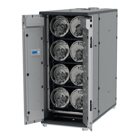
- Page 1 Array AR 3000 - AR 4000 US INSTALLATION AND OPERATION MANUAL...
- Page 2 This appliance ensures maximum comfort over a long life, with high reliability, MODEL ASSEMBLY NUMBER efficiency, performance, quality and safety. Array AR 3000 20144522 This manual provides information that is essential to the installation Array AR 4000 20144042 of the appliance. Used in conjunction with your own knowledge and expertise, it will enable you to install the appliance quickly, easily, and correctly.
-
Page 3: Table Of Contents
6.3.1 Riello Screen ....... 31 Operating Limits of the Boiler ....13 6.3.2 Cascade Screen . -
Page 4: General
GENERAL GENERAL 1.1 Warnings & Cautions Array AR 3000 and AR 4000 MBH Boilers are fully Installers and operating personnel MUST, at all times, observe modulating, high-efficiency condensing units. They represent all safety regulations. The following warnings and cautions a true industry advancement that meets the needs of today’s are general and must be given the same attention as specific energy and environmental concerns. -
Page 5: Safety Instructions
GENERAL 1.2 Safety Instructions 1.3 General Warning Observe these instructions for your safety. The installation must conform to the requirements of the authority The burner and control must be correctly installed and adjusted to having jurisdiction or, in the absence of such requirements, to the ensure safe and economical operation of the gas boiler. -
Page 6: Product Description
PRODUCT DESCRIPTION 2 PRODUCT DESCRIPTION Component Packaging method Relief Valves Drain Adapter (2.5” NPT Cardboard box on pallet 2.1 Introduction female) Flue Adapter 10”-8” Cardboard box on pallet • The gas-fired condensing Array boilers are designed to be used Mounting Anchor Plates Cardboard box on pallet in central heating systems. -
Page 7: Prolonged Shutdown
PRODUCT DESCRIPTION 2.6 Prolonged Shutdown or equipment. The sign shall read, in print size no less than one-half (1/2) inch in size, “GAS VENT DIRECTLY BELOW. KEEP CLEAR OF ALL OBSTRUCTIONS”. After prolonged shutdown, the startup procedures and the safety device test procedures of this manual shall be performed to verify 4. -
Page 8: Size And Connections
PRODUCT DESCRIPTION 2.7 Size and Connections ARRAY AR 3000, AR 4000 72.74” Ø 2.36’’ Ø 1.57’’ 15.5” 4.5” 7.75” 7.08” Ø 4’’ Ø 10’’ Ø 8’’ Ø 2’’ Ø 4’’ Ø 10’’ 23.47” 56.78” (*) Boilers’ feet may be removed for reducing overall height of 2”. -
Page 9: Technical Data
PRODUCT DESCRIPTION 2.8 Technical Data Unit AR 3000 AR 4000 Boiler Category ASME Sect.IV Type of Gas Natural Gas, Propane* Max input rate BTU/hr 3,000,000 4,000,000 (kW) (879) (1172) Min input rate BTU/hr 100,000 100,000 (kW) (29) (29) Turndown Rate 30:1 40:1 Gas Connections (NPT) -
Page 10: Assembly Components
PRODUCT DESCRIPTION 2.9 Assembly Components 26 25... - Page 11 PRODUCT DESCRIPTION Item Description Item Description Outer frame Burner head O-ring Burner flange (outer) Burner gasket Supply pipe Sight glass combustion Purge valve Igniter Gas pipe Burner tube Gas valve Burner flange (inner) Heat exchanger Gasket burner flange Pump Water shutoff valve Brass connection Flow meter Brass fitting...
-
Page 12: Efficiency Curves
PRODUCT DESCRIPTION 2.10 Efficiency Curves ARRAY AR 3000, AR 4000 100% 100% input 30% input 20% input Return water temperature (°F) @ 36 Degree Rise... -
Page 13: Regulations
4.4 Site Preparation Ensure that the site selected for installation of the Array AR 3000 and AR 4000 Boiler includes: − Access to AC Input Power at 230 VAC, three phase,L1, L2, L3, N, GND, 60 Hz. -
Page 14: Installation Clearances
Fig. 4. 24” 24” Fig. 4 Array AR 3000 and AR 4000 Forklift Handling If a crane is required, the boiler must be lifted through bands. WARNING: When lifting the boiler with crane: use bands or Fig. -
Page 15: Boiler Location
FRONT 0.75’’ 0.28’’ 29.9” 13.8” Fig. 5 Array AR 3000 and AR 4000 Crane Lifting Handling The unit must be installed on a concrete service pad (4” height), 0.28’’ with no gradient in any direction, to ensure proper condensate 0.75’’... -
Page 16: Water Quality Guidelines
− When using oxygen permeable PEX, the system must be separated from the boiler by a heat exchanger. − A correctly sized and working expansion vessel must be Fig. 9 Array AR 3000 and AR 4000 Connections installed. − Excessive flow can cause erosion damage to the heat exchanger. -
Page 17: High Limit Safety Switch
INSTALLATION 4.11 Condensate Drain and Piping “33 LWCO/Air inlet block”. At this point press the Reset button. The error will turn off. The Array Boiler is designed to condense water vapor from the Module level: flue products. Each heat exchanger of the boiler is equipped a Low Water Cut Off (LWCO) sensor is installed on top of the supply with a condensate trap (see Fig. -
Page 18: Gas Supply Piping
The maximum condensate flow cfh for AR 4000, and maintain the recommended minimum rate is 23.8 GPH for Array AR 3000 and 31.7 GPH for Array AR 4000. gas pressure at 8” w.c. while operating the burners at The drain line must be removable for routine maintenance. -
Page 19: External Gas Supply Regulator
Riello factory prior to all conversions from natural gas to propane. Take appropriate measures to prevent accidental reconnection. The installer is responsible for the proper conversion of this appliance. -
Page 20: Adjusting And Setting O Limits
INSTALLATION 4.12.5 Adjusting and Setting O Limits Array Combustion Values Gas Type Max. Fire O Min. Fire O − Insert a combustion analyzer probe into the test port Natural Gas 4.2 – 5.8 4.2 – 5.8 shown in Fig. 15 −... -
Page 21: Electrical Power Requirements
Fig. 18 Front Doors Electrical box 4.13.1 Electrical Power Requirements All of the components in the Electrical box are mounted on a DIN rail. The voltage configuration of Array AR 3000 and AR 4000 is as follows: Main Switch − 208-230V/3Ph+Neutral/60Hz... -
Page 22: Field Control Wiring
INSTALLATION included in the boiler, to be provided and wired by the installer. Power Supply connection CASCADE Supply DHW Tank Enable / 0-10 V System BMS - RS485 LINK DAMPER Door Sensor Sensor Disable Sensor 1 2 3 4 5 6 7 8 9 10 11 12 13 14 15 16 17 18 19 DHW 3-WAY CH ALARM MAIN /... -
Page 23: Outdoor Temperature Sensor
INSTALLATION Fig. 26 Combustion Air and Flue Gas Connections This output needs a minimum load of approx. 10VA to work correctly and the max load must be limited to 50VA at mains voltage. Connection of an external relay to this output to be able to switch DANGER: The condensate traps must be filled with water a higher load is only possible when an additional resistor or load or combustion gases will enter the room with a risk of an... - Page 24 INSTALLATION VENTING CONFIGURATIONS: The following figures show the acceptable piping installation for venting and combustion air. EXHAUST EXHAUST BOILER BOILER Fig. 27 All Combustion Air from Adjacent Indoor Spaces through Fig. 29 All Combustion Air From Outdoors - Inlet Air From Ventilated Indoor Combustion Air Openings Crawl Space and Outlet Air to Ventilated Attic EXHAUST...
- Page 25 INSTALLATION EXHAUST EXHAUST BOILER BOILER Fig. 31 All Combustion Air from Outdoors through Single Fig. 33 Sealed Combustion Located on Same Side with Exhaust Combustion Air Opening (horizontal) EXHAUST EXHAUST BOILER BOILER Fig. 32 Sealed Combustion Located on Same Side with Exhaust Fig.
-
Page 26: Combustion Air
INSTALLATION − For a natural draft installation the draft must not exceed - 0.25” w.c. − These factors must be planned into the vent installation. If the maximum allowable equivalent lengths of piping are exceeded, the unit will not operate properly or reliably. −... -
Page 27: Combustion Air From Outside The Building
COMMISSIONING in the following sections. with water prior to restarting it, otherwise combustion gases will enter the room with a risk of an excessive level of carbon 4.16.1 Combustion Air From Outside the Building monoxide. 5.3 Filling the Boiler Heating System Air supplied from outside the building must be provided through two permanent openings. -
Page 28: Boiler Startup Procedure
COMMISSIONING 5.5 Boiler Startup Procedure To start the boiler, do the following: − Open the manual gas shut off valve (Fig. 2). − Turn ON the main power switch (Fig. 21). − Push all Module power switches to ON (Fig. 18). −... -
Page 29: Minimum Water Flow (Heat Exchanger Protection)
COMMISSIONING Adjusting the parameters on that screen, the reset curve below All other safety and control functions associated with the boiler will modify shape and slope to meet the needs of the specific will react normally to adverse condition and override control of the application. -
Page 30: Multiple Boiler Cascade Installation And Start-Up
COMMISSIONING 5.6 Multiple Boiler Cascade Installation and Start-Up Appendix L shows an example of Array boilers installed in a cascade of three units. The built-in control system is capable of managing up to 8 boilers as a single, coordinated heating system. The logical schematic is: Demand: 0-10V / OpenTherm / On-Off System sensor D2 is T outside... -
Page 31: Operation
Installation” page 13 must be completed before attempting to start the unit. 6.2 Control Panel Description Fig. 47 Riello Screen All Array Series Boilers utilize the Touchscreen Control Panel shown in Fig. 46. This Touchscreen panel contains the basic controls for The R logo is the entry point of the Control System. -
Page 32: Boiler Screen
OPERATION − Stats button: not active; − Errors button: move to the Errors screen; − Service button: move to Service screen; − Settings button: move to Settings screen; − Back button: move to the previous screen. 6.3.3 Boiler Screen Through this screen, the following actions can be done: −... -
Page 33: Error Screen
OPERATION 6.3.6 Error Screen how long service was overdue on the system/appliance which can be useful when handling warranty claims. For each boiler, the Error screen shows the list of the last 40 errors A maximum of 15 Service moments can be logged by the 900PB, occurred on its own modules. -
Page 34: Shutdown
SHUTDOWN SHUTDOWN 8 ENVIRONMENTAL PROTECTION/DISPOSAL Environmental protection is one of the fundamental company policies of the . We regard quality of performance, economy CAUTION: Risk of system damage through frost. and environmental protection as equal objectives. When there is a frost, the heating system can freeze up if it is not Environmental protection laws and regulations are strictly adhered operational, e.g. -
Page 35: Appendix
SHUTDOWN APPENDIX APPENDIX A - WIRING DIAGRAM AWG 12 black AWG 12 gray AWG 12 brown J3-4 DEP. 4 J3-4 DEP. 3 J3-4 DEP. 2 J3-4 MANAGING AWG12 blue J3-9 DEP. 4 J3-9 DEP. 3 J3-9 DEP. 2 J3-9 MANAGING N L3 L2 L1 ⏚... - Page 36 SHUTDOWN APPENDIX WIRING DIAGRAM - MANAGING - LEFT DOOR J7-2 WATER PRESSURE SWITCH CONDENSATE PRESS. SWITCH SLAVE 4 CONDENSATE PRESS. SWITCH SLAVE 8 FLOWMETER 11 12 J6-5 FLUE SENSOR MIN+MAX GAS J6-12 J7-4 9 10 PRESSURE SWITCH J9-4 J6-10 RETURN T. SENSOR J9-2 J6-3 WATER PRESSURE...
- Page 37 SHUTDOWN APPENDIX WIRING DIAGRAM - DEPENDENT 2 / 3 / 4 - LEFT DOOR J12-2 UNIT FLOW TEMP. J12-5 J12-4 SAFETY LIMIT WATER THERMOSTAT J12-1 FLOWMETER J7-8 J7-7 FLUE PRESS. SWITCH + J7-6 CONDENSATE PRESS. SWITCH J7-2 J7-3 FOR SLAVE 2 / 3 J6-5 Only ON Slave 4 FLUE TEMP.
- Page 38 SHUTDOWN APPENDIX RIGHT DOOR J3-4 DEP. 5 J3-4 DEP. 6 J3-4 DEP. 7 J3-4 DEP. 8 J3-9 DEP. 5 J3-9 DEP. 6 J3-9 DEP. 7 J3-9 DEP. 8 (PRE-WIRED) PUMP 5 PUMP 6 PUMP 7 PUMP 8 ON-OFF POWER BUTTON Blue Blue LEFT DOOR...
- Page 39 SHUTDOWN APPENDIX WIRING DIAGRAM - DEPENDENT 5 / 6 / 7 / 8 - RIGHT DOOR...
-
Page 40: Appendix B - Connection Diagram
SHUTDOWN APPENDIX APPENDIX B - CONNECTION DIAGRAM Int. ionization CONNECTION DIAGRAM 905MN CONTROL BOARD 0...10V J9-1 Ignition 0V(GND) J9-3 BURNER J9-2 Open Thermostat interface Spark Return Room Thermostat ON/OFF J9-4 J10-1 J2 1-6 J10-2 J10-5 J10-6 J1-5 MAINS SUPPLY (120VAC, 60Hz) J1-1 COMM. - Page 41 SHUTDOWN APPENDIX CONNECTION DIAGRAM 905PB DISPLAY CONNECTION DIAGRAM 905PB DISPLAY 905PB05_3R Connector Function PC interface Connection to MN control/Modbus 905PB05_3R Display: RJ-11 Connector: RS485 / Mod BUS J25-1 J25-2 J25-3 1: GND/VSS J25-4 AL-BUS 2: ModBus_B (= Data -) J25-5 3: ModBus_A (= Data +) +24V J25-6...
-
Page 42: Appendix C - Maintenance
SHUTDOWN APPENDIX APPENDIX C - MAINTENANCE Gas Leak Inspection A qualified and adequately trained technician must perform the Verify all gas piping to ensure that there are no leaks. inspection as specified in these instructions before each heating season and at regular intervals. DANGER: To verify the gas leaks use a soap solution or a gas Servicing, inspection and adjustment must be done by a trained leak detector. -
Page 43: Appendix D - Head Available For The System
SHUTDOWN APPENDIX APPENDIX D - HEAD AVAILABLE FOR THE SYSTEM HEAD AVAILABLE (NO GLYCOL) Array ∆T = 36°F ∆T = 45°F AR 3000 9 ft 21 ft AR 4000 9 ft 21 ft HEAD AVAILABLE (50% MAXIMUM GLYCOL) ∆T = 36°F ∆T = 45°F Array AR 3000... -
Page 44: Appendix E - De-Rating For Altitude Installation
(input BTU/hr) ARRAY AR 3000 Altitude (ft) -
Page 45: Appendix F - Troubleshooting Table
SHUTDOWN APPENDIX APPENDIX F - TROUBLESHOOTING TABLE LOCKOUT CODES Error no. Error Description Checks Solutions E2PROM_READ_ERROR Internal software error Replace the power control board IGNIT_ERROR Three unsuccessful ignition a- Check gas supply a- If the gas supply pressure attempts in a row pressure;... - Page 46 SHUTDOWN APPENDIX Error no. Error Description Checks Solutions APS_NOT_OPEN Air pressure switch not working APS_NOT_CLOSED Air pressure switch not working MAX_TEMP_ERROR The external overheat a- Check module water a- Change the pump or protection is enabled or the temp. restart it; T_Supply sensor measures a b- Check the pump to verify b- Open the valves on...
- Page 47 SHUTDOWN APPENDIX Error no. Error Description Checks Solutions FLUE_PRESSURE_LOCKING Flue pressure switch is a- Check for obstruction in closed for the fourth time. the flue piping. b- Blocking errors should be recorded prior to the locking error to occur. c- Check for condensate in the hose towards the flue pressure switch to ensure it isn’t blocked.
- Page 48 SHUTDOWN APPENDIX Error no. Error Description Checks Solutions a- Check system water pressure. b- Ensure that it is above min recommended pressure (7.5PSI). LOW_WATER_PRESSURE_ERROR Low water pressure error c- Check the value of the reading of this sensor in the info screen.
- Page 49 SHUTDOWN APPENDIX Error no. Error Description Checks Solutions a- If the wiring is damaged, replace it; a- Check the integrity of the b- Verify that the wire connections; DHW_SHORTED DHW sensor shorted temperature sensor has the b- Check the DHW correct resistance values.
- Page 50 SHUTDOWN APPENDIX a- Check interconnecting wiring between boilers. b- Make sure all boilers are powered on. c- Make sure that Parameter 167 set to proper number of boilers. Cascade System: Leading d- Whichever boiler(s) loses boiler lost communication CC_LOSS_BOILER_COMM communication with the with one of the depending Master Boiler will enter boiler boilers...
-
Page 51: Appendix G - Boiler Installation (Example Drawings)
SHUTDOWN APPENDIX APPENDIX G - BOILER INSTALLATION (EXAMPLE DRAWINGS) Array AR 3000 / AR 4000 Single Unit Installation... - Page 52 SHUTDOWN APPENDIX ARRAY AR 3000 / AR 4000 Multiple Boiler Installation...
-
Page 53: Appendix H - Venting Size Data
SHUTDOWN APPENDIX Appendix H - VENTING SIZE DATA T supply / return (F°) : 176 / 140 T supply / return (F°) : 104 / 86 ARRAY AR 3000 Max. Input Min. Input Max. Input Min. Input 5.0% 5.0% 5.0% 5.0%... -
Page 54: Appendix I - Exhaust Terminals And Air Inlet Clearances
SHUTDOWN APPENDIX APPENDIX I - EXHAUST TERMINALS AND AIR INLET CLEARANCES Direct vent (sealed combustion) Fan assisted appliance (Room air for combustion) Forced air inlet Forced air inlet Gravity air inlet Gravity air inlet Exhaust terminal Exhaust terminal X1 1 foot (305 mm) X1 1 foot (305 mm) X2 See Note 1 X2 See Note 1... - Page 55 SHUTDOWN APPENDIX Horizontal venting system (sealed combustion): Vertical venting system (sealed combustion): X ≥ 4” (102 mm); X > 12” (305 mm) Y ≥ 12” (305 mm) Y = 12” (305 mm) above maximum snow level or at least 24” whichever is greater Air intake Vent...
-
Page 56: Appendix J - Sensor Resistance
SHUTDOWN APPENDIX APPENDIX J - SENSOR RESISTANCE SENSOR RESISTANCE TABLE Vent terminals Temperature °F (°C) Resistance [Ω] Testing tolerance ±10% Vent terminals 32 (0) 27396 41 (5) 22140 50 (10) 17999 59 (15) 14716 68 (20) 12099 77 (25) 10000 86 (30) 8308 95 (35) -
Page 57: Appendix K - List Of Parameters (With Ranges And Default Values)
SHUTDOWN APPENDIX APPENDIX K - LIST OF PARAMETERS (WITH RANGES AND DEFAULT VALUES) Menu item Sub item / Parameter Range Default Value Units User level Boiler Parameters (1) CH Mode 0…5 2: Installer (3) CH Setpoint 30…90 °C 1: User (185) Calc. - Page 58 SHUTDOWN APPENDIX Menu item Sub item / Parameter Range Default Value Units User level (52) DHW Instant PID I 0…1255 3: Factory (53) DHW Instant PID D 0…1255 3: Factory (60) Flow Rate Start 0.1…20 l/min 3: Factory (61) Flow Rate Lo Temp Pwr 0.1…20 l/min 3: Factory...
- Page 59 SHUTDOWN APPENDIX Menu item Sub item / Parameter Range Default Value Units User level 0) Disabled 1) General Pump 2) CH Pump 3) DHW Pump 4) System Pump 5) Cascade Pump 6) Alarm Relay 7) Filling Valve *See Appliance (125) Prog. Output 1. 8) LPG Tank 2: Installer settings...
- Page 60 SHUTDOWN APPENDIX Menu item Sub item / Parameter Range Default Value Units User level 0) Disabled 1) General Pump 2) CH Pump 3) DHW Pump 4) System Pump 5) Cascade Pump 6) Alarm Relay 7) Filling Valve *See Appliance (187) Prog. Output 5. 8) LPG Tank 2: Installer settings...
- Page 61 SHUTDOWN APPENDIX Menu item Sub item / Parameter Range Default Value Units User level (80) Max Setp Offset Up 0…40 °C 2: Installer (81) Start Mod Delay Fact 0…60 Min. 2: Installer (82) Next Module Start Rate 10…100 2: Installer (83) Next Module Stop Rate 10…100 2: Installer...
-
Page 62: Appendix L - Flowcharts
SHUTDOWN APPENDIX APPENDIX L - FLOWCHARTS SINGLE MODULE Module in Stop pump Stand-by Demand for Post pump module ready Start pump Supply Temp Start fan lower than Setpoint Module Blocking CH flow Start burner (*) error is above min_flow? BURN Burn: Based on delta of Supply sensor and Setpoint PID output is determined Is the supply... - Page 63 SHUTDOWN APPENDIX BURNER IGNITION SEQUENCE Start burner Pre-Purge 0 Pre-Purge 1 Fan on ignition speed Fan on ignition Blocking error speed within time? Pre ignition on Ignite: ignition on, Gas Valve open Flame Proving, Checking flame Flame Current Ignition Tries Above Minimal less than 3? Current?
- Page 64 SHUTDOWN APPENDIX MODULE CASCADE (STAND-ALONE BOILER) Boiler in Stop boiler Locking error stand-by pump Boiler error Locking Present? error? Blocking error Post pump Boiler Heat ready Demand? Calculate Start boiler boiler pump setpoint Boiler Temperature Clear demand Remove all higher than active modules setpoint First module...
- Page 65 SHUTDOWN APPENDIX MODULE CASCADE (STAND-ALONE BOILER): ADD/REMOVE MODULE Add module function Delay period for starting new module is 0? Open Air damper Air damper open? Are we allowed to add another dependent? Add dependent to the cascade demand Reload delay time Update demand flags...
- Page 66 SHUTDOWN APPENDIX BOILER CASCADE Stop system System in pump stand-by Locking error Boiler error Locking Present? error? Blocking error System Post pump Heat ready Demand? Start system Calculate system pump setpoint System Temperature Clear demand Remove all higher than active boilers setpoint Clear demand? First boiler...
- Page 67 SHUTDOWN APPENDIX BOILER CASCADE: ADD/REMOVE BOILER Remove Boiler function Delay period Are we allowed for starting new to add another boiler is 0? dependent? Remove dependent from Reload delay time the cascade demand Update demand flags Remove Boiler function Delay period Are we allowed to for starting new remove another...
- Page 68 SHUTDOWN APPENDIX ERROR CHECKING CYCLE Stand-by Boiler Min/Max Gas pressure Locking error switches are closed? Boiler Blocked Blocking Flue pressure error switch is closed Boiler Water Blocking pressure switch is error closed? Module High limit Locking error sensor is closed? Supply/return/ Blocking Flue sensor are...
- Page 72 RIELLO S.p.A. 37045 Legnago (VR) Tel. 0442630111 - Fax 044222378 RIELLO NORTH AMERICA 35 Pound Park Road Hingham, Massachusetts U.S.A. 02043 2165 Meadowpine Blvd Mississauga, Ontario Canada L5N 6H6 Tel. (905) 542-0303 www.riello.com/North-America/ www.rielloboilers.com The manufacturer strives to continuously improve all products. Appearance, dimensions, technical specifications, standard equipment and...
Need help?
Do you have a question about the Array AR 3000 and is the answer not in the manual?
Questions and answers