Avery Dennison SNAP 700 Operator's And Service Manual
Hide thumbs
Also See for SNAP 700:
- Operator's and service manual (176 pages) ,
- User manual (155 pages) ,
- Reference manual (22 pages)

Related Manuals for Avery Dennison SNAP 700


Summary of Contents for Avery Dennison SNAP 700
- Page 1 Operator’s and Service Manual Avery Dennison SNAP 700 Printer 028028 SNAP 700 RFID Printer 621398 Rev 4.5 3/14 © 2014 Avery Dennison Corp. All rights reserved...
- Page 2 User’s Manual—SNAP™ 700 Printer WARNING This device complies with Part 15 of the FCC Rules. Operation is subject to the following two conditions: 1) this device may not cause harmful interference, and 2) this device must accept any interference that may cause undesired operations. This Class A digital apparatus meets all requirements of the Canadian Interference Causing Equipment Regulations.
-
Page 3: Table Of Contents
User’s Manual—SNAP™ 700 Printer Table of Contents 1.0 INTRODUCTION 2.0 INSTALLATION 2.1 Preparing for the installation 2.1.1 AC Power Line 2.1.2 Location Considerations 2.1.3 PC Requirements 2.1.4 User Safety 2.2 Receiving 2.3 Unpacking 2.3.1 Removing the printer from the carton 2.3.2 Inspection / Inventory Checklist 2.3.3 Downloading Support Documentation 2.4 Printer Description... - Page 4 User’s Manual—SNAP™ 700 Printer 3.1.4 Butt Splice 3.1.5 Threading Diagrams 3.2 Sending a Print Job to the Printer 3.3 Printing Labels 3.3.1 The Control Panel 3.3.2 Printing 3.3.3 Handling the Leader 3.3.4 Feeding the stock 3.3.5 Errors 3.3.6 End of Day 3.3.7 Clearing Print Jobs 3.4 Using Pre-Printed Stock 3.4.1 Selecting the Sensor...
- Page 5 User’s Manual—SNAP™ 700 Printer 4.4 Web Server 4.4.1 Setting the Printer IP Address 4.4.2 Obtaining a DHCP Address 4.4.3 Determining the DHCP Address 4.4.4 Converting the DHCP Address to a Static Address 4.4.5 Resetting the Printer to DHCP Mode 4.4.6 Viewing and Changing the Printer Settings 4.4.7 Troubleshooting the Network Connection 5.0 MAINTENANCE 5.1 Print Head Cleaning and Handling...
- Page 6 User’s Manual—SNAP™ 700 Printer 8.2 Stock / Ink Advance 8.3 Print 8.4 Cut / Stack 10.5 Printer Errors 9.0 MECHANICAL TROUBLESHOOTING 9.1 Stock 9.2 Ink 9.3 Print 9.4 Knife APPENDICES 1. Fuse Configuration 2. Ink and Stock Transfer Types 3. Printer Specifications 4.
- Page 7 User’s Manual—SNAP™ 700 Printer Unwind Assembly – Single Shaft Design (Old) Unwind Assembly – Two Shaft Design (New) Unwind Assembly RFID 3” / 4” – Single Shaft Design (Old) Unwind Assembly RFID 3” / 4” – Two Shaft Design (New) Unwind Motor Assembly Decurler Assembly Web Guide Assembly...
- Page 8 User’s Manual—SNAP™ 700 Printer Addendum II – Short Feed Short Feed O-Ring Replacement Short Feed Assembly Short Feed Part List Revision Record...
-
Page 9: Introduction
SNAP 700 printer. Please read this section of the manual to familiarize yourself with the printer and to guide you through the initial receiving and set-up of your new SNAP 700 printer. Throughout this manual, a system of NOTES, CAUTIONS, and WARNINGS identify key information to ensure your personal safety and to proper printer operation. -
Page 10: Installation
2.1.2 Location Considerations The SNAP 700 printer weighs 60 pounds (27.2 Kg) and requires a table of sufficient quality and strength to handle this load. The printer requires an area of approximately 72" wide x 30" deep x 32" high (1.8 m x 76 cm x 81 cm). The host PC (if used) and any printer options will increase the required area. -
Page 11: Pc Requirements
AVERY DENNISON Command Language, or PCL. PCMate Platinum tag and label printing software supports the new virtual control panel feature when using the SNAP 700 printer. PCMate features higher communication speeds of the SNAP 700. Finally, it can deliver firmware upgrades from the Internet. -
Page 12: User Safety
/ receiving department. Move the carton to the installation location. 1. Move the SNAP 700 printers with a forklift, fork cart or handcart to its intended location. It is easier and safer to use one of these handling devices to move the printer. -
Page 13: Unpacking
CAUTION: Do not discard any of the packing / shipping material in case you have to move the printer to another location or return it to AVERY DENNISON for service. 3. The printer has been wrapped with shrink wrap to protect the printer from the packing material and moisture. -
Page 14: Inspection / Inventory Checklist
2.3.2 Inspection / Inventory Checklist 1. Inspect the printer for any damage that may have occurred from shipping. 2. Check the SNAP 700 printer shipping carton to be sure the following items are also included with your printer. Serial Cable A quick-disconnect power cord for 115-Volt printer) 3. -
Page 15: Printer Description
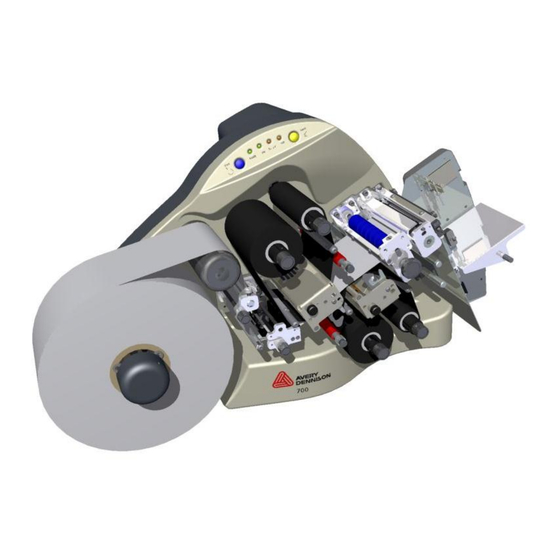
User’s Manual—SNAP™ 700 Printer SNAP 700 printer User's Manual 2.4 Printer Description Shown below are the important parts of the SNAP 700 Printer. Please take a moment to familiarize yourself with the printer. Upper Print Station Control Panel Rotary Knife Assembly... -
Page 16: Printer Configurations
2.4.1 Printer Configurations The Snap 700 comes in 2 configurations: 1 over 1 – The Snap 700 1 over 1 features one upper print head over one • lower print head, capable of printing a two sided label. -
Page 17: Setting Up The Printer
User’s Manual—SNAP™ 700 Printer 2.5 Setting up the Printer 2.5.1 Attaching the Stacker Label Stop Nip Roller Rotary Knife Stacker Sensor Assembly Switch Platform Shafts Figure 4. Rotary Knife and Stacker The stacker and knife are two separate assemblies that can be installed and/or replaced easily and quickly. -
Page 18: Checking The Main Fuse Configuration
(Line voltage of 90-132VAC @ 50-60Hz, single phase or 180-265VAC @ 50-60Hz, single phase). The main fuse(s) on the SNAP 700 printers are located inside the AC power entry receptacle on the backside of the printer (see Figure 5). The AC power entry has a fuse drawer that holds the fuse(s) and selects the appropriate line voltage. -
Page 19: Installing The Power Cord
2. Plug the power cord into the AC power entry receptacle. 2.5.4 Installing the PC Interface Cable If you will be using your SNAP 700 printers with a personal computer, one of the following computer interface cables is required: Null-modem serial cable with Part number 581139 connector •... -
Page 20: Installing Pcmate Platinum Software
The PCMate Platinum software is a Windows application used to create formats for the SNAP 700 printer as well as all other AVERY DENNISON control printers. The printer is also capable of operating directly from a mainframe when using the RS232 interface and AVERY DENNISON's command language (PCL). -
Page 21: Printing A Test Label
User’s Manual—SNAP™ 700 Printer 2.6 Printing a Test Label 2.6.1 Loading Supplies Before you can print a test label, the printer must be loaded with stock and ink. Refer to section 3.1 for instructions on loading the stock and ink. 2.6.2 Turning the Printer on 1. -
Page 22: Printing The Test Labels
User’s Manual—SNAP™ 700 Printer 2.6.4 Printing the Test Labels 1. Press the Start button. The stacker (if installed) will move the platform to its start position and the printer will begin printing the test labels. If there is no stacker installed there will be a noticeable delay in the start of the printer. 2. -
Page 23: Operation
3.0 Operation 3.1 Loading Supplies Your SNAP 700 printer is designed with upper and optional lower ink supply stations. . The ink supply station setup is dictated by the option of the printer your ordered. There is no way to change this setup at your location. - Page 24 User’s Manual—SNAP™ 700 Printer Upper Ink Rewind Arbor Upper Ink Supply Arbor Core Stop Upper Print Station Figure 7. Upper Ink Supply and Print Stations - Unloaded NOTE: The ink system is designed to rewind one roll of ink at a time. When the rewind core is full, replace it with an empty ink core.
- Page 25 User’s Manual—SNAP™ 700 Printer Rewind Core Upper Rewind Arbor Upper Ink Supply Roll Lower Print Station Upper Print Station Print Head Lower Ink Supply Roll Figure 8. Upper and Lower Ink Supply and Print Stations - Loaded 4. Fasten the ink supply to the rewind core. a.
-
Page 26: Installing Ink To The Bottom Ink Supply Station
Turning the knob clockwise will widen the web guides, while counterclockwise turns will narrow the web guides. The Upper and Lower Print Stations on the SNAP 700 printer are stationary. The rollers swing open and closed for threading and printing. These rollers are held in position for printing with latches on both the inside and outside end of the rollers. - Page 27 User’s Manual—SNAP™ 700 Printer 3. To install the stock supply roll, begin with the leading end at the top of the roll pulling off towards the stacker. 4. Slide the stock roll onto the Stock Arbor (see Figure 9). 5. Rotate the Stock Arbor knob counter-clockwise quickly to extend the fingers that hold the supply roll in place.
-
Page 28: Butt Splice
CAUTION: To prevent damage to the print head, do not use butt splices. The SNAP 700 printer is designed to allow for fast, frequent changing and loading of stock and ink. We recommend re-threading the stock rather than to using a butt splice. If you determine that splicing is faster for threading, tape the ends of the stock together. -
Page 29: Threading Diagrams
User’s Manual—SNAP™ 700 Printer 3.1.5 Threading Diagrams Upper Ink Rewind Upper Ink Unwind Stock Lower Ink Rewind Lower Ink Unwind Threading Diagram Decurler & Guide not used on Threading Diagram - RFID... -
Page 30: Sending A Print Job To The Printer
3.3 Printing Labels 3.3.1 The Control Panel The Control Panel on your SNAP 700 printer is located at the top of the machine. Figure 11 shows the control buttons and lights displayed on the printer. The buttons allow you to control the printer, and the lights indicate the status of the printer. -
Page 31: Printing
User’s Manual—SNAP™ 700 Printer Figure 11. Control Panel 3.3.2 Printing Once a print job has been sent to the printer, the Data light will come on. You can then press the Start/Stop Button to start printing. When printing starts, the stacker will move the platform to the correct position. Then the printer will start printing labels. -
Page 32: Errors
NOTE: If the error condition no longer exists, the printer will start. It is not necessary to press the Start button twice as is required with previous AVERY DENNISON printer models. If the error continues to recur, contact your local AVERY DENNISON representative. -
Page 33: Using Pre-Printed Stock
The bottom reflective sensor is also standard on the SNAP 700. This • sensor is built into the through-hole sensor and will detect a black sense mark printed on the bottom of white tape or tag stock. -
Page 34: Selecting The Sensor
User’s Manual—SNAP™ 700 Printer 3.4.1 Selecting the Sensor Select the sensor one of two ways. First, the sensor type can be selected as part of the format (see the PCMate Platinum manual or the PCL manual for details). Second, override the format sensor using the Virtual Control Panel (see section 8.0). -
Page 35: Option Menu System
User’s Manual—SNAP™ 700 Printer alignment of the sensor to the sense mark. If the sensor is not aligned with the sensor mark, the light will flash slower. If the sensor is aligned with the sense mark, the light will flash rapidly or stay on. To align the sensor to the sense mark, move the stock so that the sensor mark shows in the slot under the sensor. -
Page 36: Running Test Patterns
Voice Button Volume. Appendix 8 contains a flowchart of the Option Menu System. 3.5.1 Running Test Patterns Your SNAP 700 printer offers you two Test Patterns to run before you proceed to production. Test Pattern 1 (Narrow Setup Test Pattern), is a format designed to run on a 2”... - Page 37 User’s Manual—SNAP™ 700 Printer 8. The voice message will say, “Clearing Current Batch.” The Data light will go out. If you want to run Test Pattern 2, you must first clear the batch, and begin with Step 1 for Test Pattern 1. Figure 12a.
-
Page 38: Setting / Adjusting Voice Button Volume
The procedure for printing test pattern 3 and 4 is the same as described above. 3.5.2 Setting / Adjusting Voice Button Volume The volume level of the voice messages on your SNAP 700 printer is set at Level 3 at the factory. If you want to adjust the voice button’s volume setting on your printer, follow the steps listed below. - Page 39 User’s Manual—SNAP™ 700 Printer If you want to decrease the voice volume to Level 1 or 2, follow Steps 1-7 above and continue to press the Voice button until you reach the desired volume level. Figure 12c. Adjusting Voice Volume...
-
Page 40: Making Adjustments
4.0 Making Adjustments 4.1 Print Head Adjustments The print stations on the SNAP 700 printer are stationary. The print rollers swing open for loading stock and ink and are closed when the machine is printing. The rollers are held in the print position with a latch on both the inside and outside end of the rollers. -
Page 41: Adjusting Density (Darkness)
4.2 Adjusting the Stacker The stacker on your SNAP 700 printer is adjustable in four ways: the position of the stacker on the mounting pins, the height of the stack, the angle at which labels are accumulated in the stack, and the angle of the platform. -
Page 42: Stacker Position
User’s Manual—SNAP™ 700 Printer of the labels being printed and the material being used. There are no incorrect settings, only adjustments that allow the stacker to better accommodate the size and type of material used for the label being printed and stacked. You will soon learn the settings that work best for your labels. -
Page 43: Platform
User’s Manual—SNAP™ 700 Printer Label Stop Nip Roller Rotary Knife Stacker Sensor Assembly Switch Platform Adjustment Shafts Figure 14. Stacker Angle – Almost Vertical 4.2.4 Platform The platform angle can be adjusted in two different locations to alter the angle at which labels are stacked and stopped. -
Page 44: Virtual Control Panel
PCMate Platinum allows the operator to control the printer and make adjustments directly from the PC. The Virtual Control Panel (VCP) shows at the bottom of the PCMate Platinum screen when a SNAP 700 printer is properly connected (see figure 21). Printer Selection Box Printer Controls and Lights... -
Page 45: Changing Printer Settings In Pcmate (Printer Settings)
User’s Manual—SNAP™ 700 Printer 4.3.2 Changing Printer Settings in PCMate (Printer Settings) Click on the “Show Settings” button on the VCP to bring up the Settings Window (see figure 22). Figure 22: Virtual Control Panel with Show Setting Window Printer settings have several pages. Click on the tab to select one of the pages. 4.3.3 Print/Cut Adjust (VCP Print/Cut Adjust Tab) The cut adjust will help the printer cut in the right place with relation to the sense mark on pre-printed tape. -
Page 46: Selecting The Printer Language (Vcp Options Tab)
Refer to the PCMate Platinum manual for details. 4.3.4 Selecting the Printer Language (VCP Options Tab) The SNAP 700 printer has the capability of presenting both text and voice messages in multiple languages. The printer is shipped with several languages installed. When performing an upgrade, however, the Operating System (OS) upgrade file contains only the English language messages. -
Page 47: Setting The Date And Time (Vcp Options Tab)
5 ips (the third speed in the printer’s speed list of 3, 4, and 5 ips), the SNAP 700 printer would use 6 ips, which is the third speed in its speed list of 3, 4.5, 6, and 7 ips. -
Page 48: Selecting The Flagging Mode (Vcp Options Tab)
• Side-step – This selection is for the High Volume Stacker, which is not • available for the SNAP 700 printer. Do not select this. Disabled – Disables flagging. No flagging will be done. • 4.3.9 Selecting the Sense Mark Type (VCP Options Tab) This selection allows you to override the sense mark type (none, top reflective or bottom reflective) selected in the format. -
Page 49: Viewing The Life Counts (Vcp Versions/History Tab)
User’s Manual—SNAP™ 700 Printer 4.3.11 Viewing the Life Counts (VCP Versions/History Tab) The SNAP 700 printer maintains a count of the total number of labels printed, and the total number of inches of material. Also, there is a resettable label counter. -
Page 50: Print Quality (Vcp Arbor Tension Adjust Tab)
User’s Manual—SNAP™ 700 Printer 4.3.13 Print Quality (VCP Arbor Tension Adjust Tab) If there are problems with the thermal transfer ink wrinkling, you can adjust the tensions of the arbors to remove the wrinkles. Click on the “Arbor Tension Adjust” tab and slide the Unwind and Rewind arbor tensions in order to remove the wrinkles. -
Page 51: Web Server
User’s Manual—SNAP™ 700 Printer 4.4 Web Server The SNAP Printer Web Server provides the ability to set up the printer for an Ethernet connection, view and change the printer settings remotely over a network, and upgrade the printer remotely over a network. The printer can get a network (IP) address via DHCP. -
Page 52: Determining The Dhcp Address
There are two Ethernet connectors on the back of the printer. One is on the motherboard and is not used. You need to have a network interface card installed on the printer to use it. Contact Avery Dennison Customer Service if you need a card. It can be installed in the field Network Interface Card Motherboard. -
Page 53: Converting The Dhcp Address To A Static Address
User’s Manual—SNAP™ 700 Printer If no IP address prints on the Network ID Test Label, the printer may not have completed the DHCP process. Wait a few minutes and try again. If there is still a problem, make sure the network cable is connected proper and check the other network connections. -
Page 54: Resetting The Printer To Dhcp Mode
User’s Manual—SNAP™ 700 Printer The DHCP address is shown in the IP Address box and the mode is DHCP. Enter the static IP address in the IP Address box and click the “Submit as Static address” button. At this time, the IP address is set to the static address and the web server will no longer be available. -
Page 55: Viewing And Changing The Printer Settings
User’s Manual—SNAP™ 700 Printer 4.4.6 Viewing and Changing the Printer Settings Access the web server by opening a browser on any computer connected to the network. Enter the printer’s IP address in the address bar and press Enter. The following window will appear: The values shown are the current printer settings. -
Page 56: Troubleshooting The Network Connection
User’s Manual—SNAP™ 700 Printer 4.4.7 Troubleshooting the Network Connection If there are problems, perform this procedure. You will need to obtain a valid IP address from your network administrator. 1. Turn the printer off and connect a standard computer monitor and keyboard to connections on the printer’s motherboard. -
Page 57: Maintenance
Wear anti-static gloves at all times when handling print heads to prevent oils on your hands from contaminating the print head. The SNAP 700 printer optional spare parts kit contains an anti-static wrist strap and gloves. -
Page 58: Cleaning Procedures
CAUTION: AVERY DENNISON recommends Master Cleaning Kit #921341K for use in cleaning print heads. 1. Before cleaning any part of your SNAP 700 printer, turn off the power to the printer. 2. To avoid damaging the print head, wear the anti-static wrist strap (which must be in contact with the skin and be tight). -
Page 59: Print Head Replacement
User’s Manual—SNAP™ 700 Printer 5.2 Print Head Replacement When you see voids in the printing, and print quality does not improve, even after cleaning the heads, it is time to replace the print heads. Follow the procedures listed below. Turn off the power to the printer. 2. - Page 60 User’s Manual—SNAP™ 700 Printer locating pins. Pull the head towards the stacker end of the printer. It will slip out from under the flat retaining springs located at both ends of the head. 9. Unplug the two cables that connect to the print head by grasping the print head cable, rocking it gently (see Fig.
- Page 61 User’s Manual—SNAP™ 700 Printer be inside of the connectors located on the print head. 13. Replace the stock and ink supplies, and double-check your work. 14. Turn on the power to the printer. 15. You must set the printhead category to adjust for variations in the individual printheads.
-
Page 62: Lubrication
5.4 Rotary Knife Assembly The rotary knife assembly for the SNAP 700 printer is fastened directly to the frame. It has been designed to deliver an average of two million cuts if used with woven tapes and four million cuts when used with coated tapes, provided no foreign objects are inserted into the assembly that could damage the knife blades. -
Page 63: Removing And Replacing The Knife Assembly
User’s Manual—SNAP™ 700 Printer 5.4.1 Removing and Replacing the Knife Assembly WARNING: When adjusting, removing, or replacing the knife assembly, you must turn off the power to the printer to avoid personal injury. 1. Turn off the power to the printer. 2. - Page 64 User’s Manual—SNAP™ 700 Printer knife. The Gold color spring is on the inboard end and the Light Blue spring is on the outboard end of the assembly. 8. Remove the Bridge Blade, Knife Output from the Stationary Knife by removing the two 8-32 x ¼ BHCS. 9.
- Page 65 User’s Manual—SNAP™ 700 Printer 11. Insert the rotary knife blade with the long end and flat to the inboard side of the printer. 12. Place the Gold torsion springs on the inboard end of the stationary knife. The “L” bent tang of the spring will extend towards the back of the knife. The cutting edge of the blade will be to the left of the rotary knife pointing down.
-
Page 66: Adjust The Knife Home Position
User’s Manual—SNAP™ 700 Printer 5.4.2 Adjust the Knife Home Position To adjust the Knife Home Position, follow the procedure listed below. 1. Insert a flat blade screwdriver into the slot in the end of the knife. 2. Rotate the screwdriver counterclockwise until you hear an audible click. 3. -
Page 67: Service Adjustments
User’s Manual—SNAP™ 700 Printer 6.0 Service Adjustments 6.1 Stock (Web) Guide Position The stock (web) guide is set at the factory to center the stock to the printed image. If a slight mechanical adjustment is needed, follow these steps. 1. Locate the two plastic thumb screws under the Stock (Web) Guide mount shaft. - Page 68 User’s Manual—SNAP™ 700 Printer 3. Loosen the outer pivot screw by making one complete turn (see Fig. 19a). 4. The two setscrews move the stationary outboard end of the knife to increase or decrease the shear. 5. To increase the shear, loosen the right setscrew ¼ turn (see Fig. 19b) and tighten the left setscrew (see Fig.
-
Page 69: Upgrading The Printer Firmware
7.1 Introduction The SNAP 700 printer firmware can be updated electronically using “UPG” files received from Avery Dennison. A “UPG” file is a software file with “.upg” as an extension. Files are either “zip” files, which must be extracted/unzipped, or UPG files. -
Page 70: Getting The Upg File
You may download the upgrade file as follows: 1. Go to www.monarch.averydennison.com. 2. On the left, click “SUPPORT”, then “Printer Utilities, Firmware & Drivers” 3. Next in the Firmware second (2 one down), click “Apparel Models – SNAP 500 & SNAP 700”... -
Page 71: Performing The Upgrade
User’s Manual—SNAP™ 700 Printer 4. Choose one of 3 upgrade files. For example, for version 3.32.13.12: a. V3_32_13_12.upg – This is the complete upgrade and includes English and all alternate language messages and prompts b. V3_32_13_12_OS.upg – This is the upgrade with English only c. -
Page 72: Upgrading Through Pcmate
User’s Manual—SNAP™ 700 Printer 7.4.2 Upgrading through PCMate 1. Once you have received the upgrade file through D2Comm, check that the UPG file is in the “C:\D2Comm\Control\” folder. 2. Start PCMate Platinum. The following screen will appear. 3. Click on the Yes button to start the upgrade. Clicking on the No button start PCMate Platinum. - Page 73 User’s Manual—SNAP™ 700 Printer 5. In the box under Upgrade Schedule, it will say Upgrade Now. If you click on the box, a drop down list will offer the following choices: Upgrade Now – this will cause the printer to be upgraded when you click on the Start Upgrade button.
- Page 74 User’s Manual—SNAP™ 700 Printer 8. Once the files are on the printer, the following window will appear. Do not click on any buttons until the upgrade finishes. 9. The printer will reboot, ring the chimes, and may say, - Upgrade in progress. Please wait - Programming MCB.
-
Page 75: Upgrading Through Usb Flash Drive
User’s Manual—SNAP™ 700 Printer 7.4.3 Upgrading through USB Flash Drive 1. Make sure the file you received has a “.upg” extension. If it has a “.zip” extension, then extract/unzip to get the upgrade file. 2. Place the upgrade file in the root directory of a USB flash drive. 3. - Page 76 User’s Manual—SNAP™ 700 Printer Connecting to the Printer through Filezilla 1. Start the Filezilla application. The following window will appear: Refresh icon 2. Enter the printer’s IP address in the host box, enter the printer’s username (Avery) and password (Dennison) in the corresponding boxes, and click the Quickconnect button.
- Page 77 User’s Manual—SNAP™ 700 Printer Printer’s Root Directory Upgrade File 6. To transfer the file, simply drag it from the bottom left pane to the bottom right pane, or double click the upgrade file. There may be a folder in the root directory of the printer called PAXA.
- Page 78 User’s Manual—SNAP™ 700 Printer 7. To upgrade the printer, first open a browser window, enter the printer’s IP address in the address bar, and press Enter. The following window will appear. 8. Click the Upgrade Firmware button. The printer will perform the upgrade operation automatically.
-
Page 79: Electrical Troubleshooting
User’s Manual—SNAP™ 700 Printer 8.0 Electrical Troubleshooting 8.1 Power Up / Sign On / Communications Problem Probable Cause Corrective Action LEDs do not light. 1) Incorrect supply voltage. 1) Confirm that the AC entry is configured for the line voltage intended to be applied to the machine. - Page 80 1) Reconfigure PCMate Platinum for AVERY PCMate Platinum . DENNISON PCL printer as per your PCMate Platinum manual. 6) Faulty Mother Board 1) Replace the Mother Board. IF THE RECOMMENDED CORRECTIVE ACTIONS DO NOT RESOLVE THE PROBLEM (S), CONTACT YOUR LOCAL AVERY DENNISON REPRESENTATIVE.
-
Page 81: Stock / Ink Advance
/ display. 3) Stock is bound. 1) Remove and rethread the stock. 4) Ink is bound. 1) Remove and rethread the ink. IF THE RECOMMENDED CORRECTIVE ACTIONS DO NOT RESOLVE THE PROBLEM (S), CONTACT YOUR LOCAL AVERY DENNISON REPRESENTATIVE. -
Page 82: Print
Refer to section 6.2, Stock (Web) Guide Width Adjustments. 3) Stock Arbor is not tight. 1) Check and adjust as needed. Refer to section 3.1 Loading Supplies. IF THE RECOMMENDED CORRECTIVE ACTIONS DO NOT RESOLVE THE PROBLEM (S), CONTACT YOUR LOCAL AVERY DENNISON REPRESENTATIVE. - Page 83 1) Set print head pressure. Refer to section pressure. 4.1.1, Adjusting Print Head Pressure. 5) Worn printer roller. 1) Contact your local AVERY DENNISON representative. IF THE RECOMMENDED CORRECTIVE ACTIONS DO NOT RESOLVE THE PROBLEM (S), CONTACT YOUR LOCAL AVERY DENNISON REPRESENTATIVE.
-
Page 84: Cut / Stack
Adjustment. Knife will not cut. 1) Knife blades are dull. 1) Refer to section 5.4.1, Removing and Replacing the Knife assembly. IF THE RECOMMENDED CORRECTIVE ACTIONS DO NOT RESOLVE THE PROBLEM (S), CONTACT YOUR LOCAL AVERY DENNISON REPRESENTATIVE. -
Page 85: Printer Errors
User’s Manual—SNAP™ 700 Printer 10.5 Printer Errors Printer errors are indicated by either the Supply or Error light being on. When the Supply light is on, the printer supplies (stock or ink) require attention. Generally, this means the stock or one of the ink rolls is empty, or the stacker is full. - Page 86 MCB BAD STACK ERROR continues to occur, report the error and the MCB KNF FLIT TBL TOO circumstances that cause it to Avery Dennison Service. These errors are caused by errors in the MCB KNIFE STATE TOO software and are not caused by hardware failures.
- Page 87 User’s Manual—SNAP™ 700 Printer Voice Message Prompt Description lower (upper) INK OUT BOTTOM (TOP) This error indicates that the ink on the specified print print station ink roll is station is either missing or broken, or the supply roll empty is empty.
- Page 88 User’s Manual—SNAP™ 700 Printer Voice Message Prompt Description Missed contrast MISSED CONTR The format specifies a contrast sense mark, but no sense mark SENSEMARK sense mark was found. Possible causes are misalignment of the sensor to the sense mark or incompatibility of the sense mark and the sensor type.
- Page 89 User’s Manual—SNAP™ 700 Printer Voice Message Prompt Description Contrast sense mark CONTR SENSEMARK CAL When first running a format specifying a contrast calibration error ERROR sense mark, or after a missed sense mark error, the printer automatically calibrates the sensor. This error indicates that the printer could not calibrate the sensor.
- Page 90 MCB with the power off, then replacing it. This will also reset all the printer settings (print and cut adjust, baud rate, cutter enable, etc.) to their default values. IF THE RECOMMENDED CORRECTIVE ACTIONS DO NOT RESOLVE THE PROBLEM (S), CONTACT YOUR LOCAL AVERY DENNISON REPRESENTATIVE.
-
Page 91: Mechanical Troubleshooting
1) Be sure the nip roller is free to rotate and moves easily in the bearing slots. Check for a loose drive gear. IF THE RECOMMENDED CORRECTIVE ACTIONS DO NOT RESOLVE THE PROBLEM (S), CONTACT YOUR LOCAL AVERY DENNISON REPRESENTATIVE. -
Page 92: Ink
Stock is popping in front 1) Knife blades are dull. 1) Refer to section 5.4.1, Removing and of the knife. Replacing the Knife Assembly. IF THE RECOMMENDED CORRECTIVE ACTIONS DO NOT RESOLVE THE PROBLEM (S), CONTACT YOUR LOCAL AVERY DENNISON REPRESENTATIVE. -
Page 93: Appendices
Appendices 1. Fuse Configuration The main fuse(s) on the SNAP 700 are located inside the AC power entry receptacle. The entry has a fuse drawer that holds the fuse(s) and selects the appropriate line voltage. If the number in the window DOES NOT match the AC line voltage intended to be supplied to the printer, DO NOT plug the power cord in. -
Page 94: Ink And Stock Transfer Types
User’s Manual—SNAP™ 700 Printer 2. Ink and Stock Transfer Types Transfer Type values associated with the XT commands. Value Transfer Type Heat Seal & SD-1111 Ink Fabric 2800 & TT-1111 Ink Fabric 2800 & HR-3111 Ink Fabric 2800 & TT-3111 Ink Fabric 2800 &... - Page 95 User’s Manual—SNAP™ 700 Printer Value Transfer Type 601SST Fabric & CT-1111 Ink 591SST/601SST Fabrics & CT-1115 Ink 591SST/601SST Fabrics & CT-1117 Ink 591SST Fabric & CT-1112 Ink 601SST Fabric & CT-1112 Ink 4900NWT / 4900HSA & HS1111 1800FRA & TW1111 1800FRA &...
-
Page 96: Printer Specifications
User’s Manual—SNAP™ 700 Printer 3. Printer Specifications Print Method: 5” web thermal transfer two sided printer Speeds: 3 IPS (76.2mm/second), 4.5 IPS (114.3mm/second), 5 IPS (127mm/second), 6 IPS (152.4mm/second), 7 IPS (177.8mm/second), 8 IPS (202.3mm/second), 10 IPS (254mm/second), 12 IPS (304.8mm/second) Label Size Standard Feed: Min:... - Page 97 Ink Ribbon AVERY DENNISON standard thermal colors and widths AVERY DENNISON white plastic core: Maximum Ink O.D. 3.5” Ink widths: With Metric Adapter - 25mm to 127mm metric widths in 5mm increments. With Inch Adapter - 1” to 5” inch widths in ¼” increments.
-
Page 98: Installation Procedure
User’s Manual—SNAP™ 700 Printer 4. Instructions for Factory / Field Installation of Top Sensor Assemblies 620006 & 620007 These Sensors are alike in mechanical configuration. 620006 is a Contrast Sensor Assembly only and 620007 is a Color Contrast Assembly Installation Procedure 1. - Page 99 User’s Manual—SNAP™ 700 Printer 5. Create a sub-assembly of the Plastic Collet, the Fiber Optic Slide Shaft, The Fiber Optic Cable and the O-Ring. Slide the two cables at the rear of the Fiber-Optic Assembly through the Collet as shown. This must be done by sliding one cable through, then sliding cable end of the other cable through parallel to the first.
- Page 100 User’s Manual—SNAP™ 700 Printer 7. Install the “O”-Ring in the front groove behind the Fiber-Optic Tube. (See pics below for clarity)
- Page 101 User’s Manual—SNAP™ 700 Printer 8. Assemble Sensor Mounting Bracket to Sensor body with two 6-32 x ¼ Button Head Screws. MCB POWER CABLE CONNECTOR SENSOR SENSOR MOUNTING BRACKET (4) 10-32 X 1/4 BUTTON HEAD SCREWS 9. Remove two plastic Jam Nuts from Sensor, slide ends of “Y” Cable through nuts and secure with two 7/32 E-Rings.
-
Page 102: Programming The Contrast Sensors
Sensor. 5. Programming the Contrast Sensors There are two optional contrast sensors available for the SNAP 700 printer. 620006-1 is the standard contrast sensor. It works well in most situations where there is significant contrast between the material background and the sense mark. In situations where there is less contrast between the material and the sense mark, or the material and sense mark are of similar colors, the 620007-1 Color Contrast Sensor may be required. -
Page 103: Programming The Contrast Sensor
User’s Manual—SNAP™ 700 Printer Programming the Contrast Sensor The figure below shows the control panel for the Contrast Sensor. The sensor can detect a light sense mark on dark material (L) or a dark sense mark on light material (D). In each mode, the control switch can be set to RUN or TEACH. To teach the sensor, thread the printer with the stock to be used. -
Page 104: Programming The Color Contrast Sensor
User’s Manual—SNAP™ 700 Printer Move the configuration switch to either the RUN L or RUN D position, depending on the sense mark. Programming the Color Contrast Sensor The figure below shows the control panel for the Color Contrast Sensor. configuration switch has three positions: Q1 –... - Page 105 User’s Manual—SNAP™ 700 Printer Move the configuration switch to RUN position. Item Part # Description 594008 Collet, Sensor mount 624029 Mount, Fiber Optic 624026 Shaft, Turn Bar 581316 Bracket, Color Sensor, Mount 581181 Sensor, Contrast, Sick 581182 Sensor, Color, Sick 990089 10-32 x ¼...
-
Page 106: Instructions For Factory / Field Installation Of High Speed Verifier Assembly 620008F (Factory) And 620008 (Field)
User’s Manual—SNAP™ 700 Printer 6. Instructions for Factory / Field Installation of High Speed Verifier Assembly 620008F (Factory) and 620008 (Field) Installation Procedure - Mechanical Disconnect Power to Printer. Disconnect Stacker Interface Cable. Remove the Rear Cover (save screws). Install the Bracket, Verifier, Mount Base (621303) on the back of the Upright Frame in the (2) 10- 32 Pem Nuts in the upper most right side of the Frame. - Page 107 User’s Manual—SNAP™ 700 Printer Install the Bracket Verifier Mount (621307A) to the Bracket, Verifier Upright (621304) as shown using a washer, set screw and knob. Attach the Verifier to the Assembly, Bracket, Verifier Mount with (2) 6-32 x 3/8 Cap Screws (990016). 991204 –...
-
Page 108: Installation Procedure - Electrical
User’s Manual—SNAP™ 700 Printer Installation Procedure - Electrical 1) Facing the back of the Printer, remove the existing connector plate and screws and discard. REMOVE REMOVE 2) Assemble Internal Verifier Cable into slot and secure with hardware supplied on 581129. 581129 - INTERNAL VERIFIER CABLE 3) Mount J1 (5 wire, 10 pin connector) to MCB J7. -
Page 109: Installation - Rear Cover
User’s Manual—SNAP™ 700 Printer Installation – Rear Cover 1) Insert the Template supplied into the cover hole below and closest to the above Verifier Bracket Assembly. Bending the Template slightly to match the Cover contour will assure a more accurate location. 2) Scribe a line around the inner cutout of the Template. -
Page 110: Warranty Policy
− Consumable elements are not covered. Consumable elements are those that show normal wear from typical equipment usage including, without limitation, printheads, knives, rollers in contact with the web, and sonic units. Avery Dennison reserves the right to determine which elements are defined as “consumable.”... -
Page 111: Service
Americas (United States, Canada, Mexico, Central America, Caribbean Region, and South America excluding Brazil). − Outside the US, the local Avery Dennison office is responsible for equipment and parts warranty. Customers must ensure coverage during machine purchase. − Equipment purchased and exported to regions outside local Avery Dennison office coverage are not covered by warranty. -
Page 112: Option Menu System Flowchart
User’s Manual—SNAP™ 700 Printer 8. Option Menu System Flowchart PRESS START BUTTON TO ACCEPT THE CURRENT OPTION PRESS AND HOLD VOICE BUTTON UNTIL OPTION PRESS VOICE BUTTON TO GO TO THE NEXT OPTION MENU BEGINS NOTE: PRESS AND HOLD THE VOICE BUTTON AT ANY TIME TO EXIT THE VOICE MENU SYSTEM. PRESS START FOR PRESS START FOR TEST PRESS START FOR... -
Page 113: Electrical Drawings
User’s Manual—SNAP™ 700 Printer Electrical Drawings... -
Page 114: Electrical System Schematic
User’s Manual—SNAP™ 700 Printer Electrical System Schematic AC ENTRY 341111 24V CONTROL RELAY PART OF 591141 FLYBACK DIODE PART OF 591141 POWER SUPPLY 24V HARNESSED 581119F FACTORY 591141 LINE +24V COMM 581119K FIELD LINE CORD GROUND 181134 RETURN 581113 581112 NEUTRAL MINI FP 115V OPERATION... -
Page 115: Harness Connections
User’s Manual—SNAP™ 700 Printer Harness Connections... - Page 116 User’s Manual—SNAP™ 700 Printer FEED FEED MOTOR - J13 24V - J21 KNIFE MOTOR - J15 KNIFE KNIFE HOME - J27 SPEAKER SPEAKER - J38 UNWIND MEDIA UNWIND - J17 STACKER S2 PRINT HEAD - J32 STACKER - J34 S2 INK UNWIND - J19 STATION 2 S2 INK REWIND - J20 S2 HEAD OPEN - J25...
-
Page 117: Mechanical Assembly Drawings
User’s Manual—SNAP™ 700 Printer Mechanical Assembly Drawings... -
Page 118: Unwind Assembly - Single Shaft Design (Old)
User’s Manual—SNAP™ 700 Printer Unwind Assembly – Single Shaft Design (Old) ***If you have a unwind with a single shaft (item 6) and need a replacement, order parts 05623020, 05634051, and 05996311 instead. -
Page 119: Unwind Assembly - Two Shaft Design (New)
User’s Manual—SNAP™ 700 Printer Unwind Assembly – Two Shaft Design (New) -
Page 120: Unwind Assembly Rfid 3" / 4" - Single Shaft Design (Old)
User’s Manual—SNAP™ 700 Printer Unwind Assembly RFID 3” / 4” – Single Shaft Design (Old) ***If you have a unwind with a single shaft (item 5) and need a replacement, order parts 05623020, 05634051, and 05996311 instead. -
Page 121: Unwind Assembly Rfid 3" / 4" - Two Shaft Design (New)
User’s Manual—SNAP™ 700 Printer Unwind Assembly RFID 3” / 4” – Two Shaft Design (New) -
Page 122: Unwind Motor Assembly
User’s Manual—SNAP™ 700 Printer Unwind Motor Assembly... -
Page 123: Decurler Assembly
User’s Manual—SNAP™ 700 Printer Decurler Assembly... -
Page 124: Web Guide Assembly
User’s Manual—SNAP™ 700 Printer Web Guide Assembly... -
Page 125: Sensor Tray Assembly
User’s Manual—SNAP™ 700 Printer Sensor Tray Assembly * Items 13 and 30 ordered as one Assembly, Part no. 624087 – Assy, Rear Support **Items 14 and 30 ordered as one Assembly, Part no. 624088 – Assy, Front Support Parts shown exploded for clarity purposes... -
Page 126: Sensor Tray Assembly Rfid
User’s Manual—SNAP™ 700 Printer Sensor Tray Assembly RFID * Items 13 and 39 ordered as one Assembly, Part no. 624087 – Assy, Rear Support **Items 14 and 39 ordered as one Assembly, Part no. 624088 – Assy, Front Support Parts shown exploded for clarity purposes... -
Page 127: Top Print Head Assembly
User’s Manual—SNAP™ 700 Printer Top Print Head Assembly Items 9 and 26 are not used in the RFID Printer. -
Page 128: Bottom Print Head Assembly
User’s Manual—SNAP™ 700 Printer Bottom Print Head Assembly... -
Page 129: Print Head Assembly
User’s Manual—SNAP™ 700 Printer Print Head Assembly... -
Page 130: Platen Roller Assembly
User’s Manual—SNAP™ 700 Printer Platen Roller Assembly... -
Page 131: Ink Arbor Assembly
User’s Manual—SNAP™ 700 Printer Ink Arbor Assembly... -
Page 132: Ink Unwind / Rewind Motor(S) Assembly
User’s Manual—SNAP™ 700 Printer Ink Unwind / Rewind Motor(s) Assembly... -
Page 133: Drive Assembly
User’s Manual—SNAP™ 700 Printer Drive Assembly... -
Page 134: Knife Assembly
User’s Manual—SNAP™ 700 Printer Knife Assembly... - Page 135 User’s Manual—SNAP™ 700 Printer Items 1 & 3 ordered as a kit only, includes both torsion springs items 4 & 5. Parts shown exploded for clarity purposes * See Addendum II for Knife Parts List of machines with short feed option*...
-
Page 136: Nip Roller Assembly
User’s Manual—SNAP™ 700 Printer Nip Roller Assembly * See Addendum II for Nip Roller Parts List of machines with short feed option*... -
Page 137: Knife / Drive Motors Assembly
User’s Manual—SNAP™ 700 Printer Knife / Drive Motors Assembly... -
Page 138: Knife / Drive Motors Assembly Rfid
User’s Manual—SNAP™ 700 Printer Knife / Drive Motors Assembly RFID... -
Page 139: Rfid Reader Assembly
User’s Manual—SNAP™ 700 Printer RFID Reader Assembly... -
Page 140: Covers Assembly
User’s Manual—SNAP™ 700 Printer Covers Assembly... -
Page 141: Cooling Fans Assembly
User’s Manual—SNAP™ 700 Printer Cooling Fans Assembly... -
Page 142: Stacker Assembly (Sheet 1 Of 2)
User’s Manual—SNAP™ 700 Printer Stacker Assembly (Sheet 1 of 2) -
Page 143: Stacker Assembly (Sheet 2 Of 2)
User’s Manual—SNAP™ 700 Printer Stacker Assembly (Sheet 2 of 2) -
Page 144: Stacker Parts List
User’s Manual—SNAP™ 700 Printer Stacker Parts List ITEM PART NO. DESCRIPTION ITEM PART NO. DESCRIPTION 628010 FRAME, STACKER, 700 989986 4-40 ES NUT HARNESS, DOWN STACKER ASSY, 628004 BRACKET, STACKER MOUNT 581177 PROGRAMMED WITH GEAR 6-32 X 250 PHILLIPS PAN HEAD 990273 WASHER, #10 BELLEVILLE 991372... -
Page 145: Addendum I - Printing And Supplies Handling Procedure
2. While AVERY DENNISON has designed the printer to be reasonably quiet, select an area where repetitious noise from printing and cutting processes is acceptable and where heat generated by the printer can be quickly dissipated. - Page 146 The information contained herein is believed to be reliable but AVERY DENNISON makes no representations concerning the accuracy or correctness of the data. This product, the related media and supplies, like any other should be tested by the customer/user thoroughly under end user conditions to ensure the product meets the particular requirements.
- Page 147 User’s Manual—SNAP™ 700 Printer Addendum II – Short Feed Machines equipped with short feed option use different parts noted after O-ring replacement instructions. Machines with short feed option have ability to handle labels as short as .66” long. O-rings on short feed nip rollers are wear items and require occasional changing. It is recommended to change all O-rings at same time.
- Page 148 User’s Manual—SNAP™ 700 Printer NIP ROLLER BRACKET "O" RING BELT RUBBER ROLLER RUBBER ROLLER "O" RING BELT NOTE: "O" RING BELTS SHOWN STATIC BRUSH LOOSE FOR CLARITY. WHEN INSTALLING BELTS, THEY WILL BE TIGHT WHEN STRETCHED. THUMB SCREW BRIDGE BLADE NIP ROLLER BRACKET...
- Page 149 User’s Manual—SNAP™ 700 Printer Short Feed Assembly...
- Page 150 User’s Manual—SNAP™ 700 Printer Short Feed Part List ITEM PART NO. DESCRIPTION 197319 TORSION SPR FRONTDC KNIFE 357029 TORSION SPR BACK, DC KNIFE 357093 ASSEMBLY, STATIONARY KNIFE 448010 STATIC BRUSH 517021 BLOCK, SHEAR ADJUST 627024 BRACKET, BRIDGED BLADE 627091 ASSEMBLY, GROUND ROTARY 627301 SHAFT, SHORT FEED NIP EXT 627302...
- Page 151 User’s Manual—SNAP™ 700 Printer Avery Dennison Technical Support Product / Services Installation Report (For office use) Customer: Failure Report #: Address: Service Report #: Failure Reported Date: Model #: Contact: Serial #: (For office use) Phone #: Mfg. Date: Within...
- Page 152 Added support for RFID printers in the parts pages Added updates to many of the parts pages for the latest production parts Updated text to support both SNAP 700 and SNAP 700 RFID Added addendum for Printer and Supplies Handling.
- Page 153 User’s Manual—SNAP™ 700 Printer 028028 Avery Dennison 170 Monarch Lane Miamisburg, OH 45342 1-800 543-6650 (In the U.S.A.) 1-800-387-4740 (In Canada) www.averydennison.com...
Need help?
Do you have a question about the SNAP 700 and is the answer not in the manual?
Questions and answers