Avery Dennison snap 700 Operator's And Service Manual
Hide thumbs
Also See for snap 700:
- User manual (155 pages) ,
- Operator's and service manual (153 pages) ,
- Reference manual (22 pages)

Subscribe to Our Youtube Channel
Related Manuals for Avery Dennison snap 700


Summary of Contents for Avery Dennison snap 700
- Page 1 Operator’s and Service Manual Avery Dennison SNAP 700 Printer 028028 SNAP 700 RFID Printer 05621398 Rev 4.8 02/17 © 2017 Avery Dennison Corp. All rights reserved Classification: Avery Dennison - Public...
- Page 2 2) this device must accept any interference that may cause undesired operations. This Class A digital apparatus meets all requirements of the Canadian Interference Causing Equipment Regulations. Cet appareil numerique de la classe A respecte toutes les exigences du Reglement sur le material broilleur du Canada Classification: Avery Dennison - Public...
- Page 3 User’s Manual—SNAP™ 700 Printer Classification: Avery Dennison - Public...
-
Page 4: Table Of Contents
Connecting the networking cable 3.7.3 Setting the Printer IP Address PCMate Platinum Software Installation Printing a Test Label 3.9.1 Loading Supplies 3.9.2 Turning the Printer on 3.9.3 Selecting the Test Format 3.9.4 Printing the Test Labels Classification: Avery Dennison - Public... - Page 5 Selecting the Printer Language 5.3.5 Setting the Date and Time 5.3.6 Enabling or Disabling the Cutter 5.3.7 Selecting the Print Speed 5.3.8 Selecting the Flagging Mode 5.3.9 Selecting the Sense Mark Type 5.3.10 Setting the Default Transfer Classification: Avery Dennison - Public...
- Page 6 Getting UPG file without using D2Comm Performing the Upgrade 8.4.1 Unzipping the file 8.4.2 Upgrading through PCMate 8.4.3 Upgrading through USB Flash Drive 8.4.4 Upgrading through the Webserver ELECTRICAL TROUBLESHOOTING Power Up / Sign On / Communications Classification: Avery Dennison - Public...
- Page 7 11.8 8. Option Menu System Flowchart 12.0 ELECTRICAL DRAWINGS 12.1 Electrical System Schematic 12.2 Harness Connections 13.0 MECHANICAL ASSEMBLY DRAWINGS 13.1 Unwind Assembly 13.2 Unwind Assembly RFID 3” / 4” 13.3 Unwind Motor Assembly 13.4 Decurler Assembly Classification: Avery Dennison - Public...
- Page 8 13.23 Stacker Assembly (Sheet 2 of 2) 14.0 ADDENDUM I – HANDLING PROCEDURES 15.0 ADDENDUM II – SHORT FEED 15.1.1 Short Feed O-Ring Replacement 15.1.2 Short Feed Assembly 15.1.3 Short Feed Assembly Part List 16.0 REVISION RECORD Classification: Avery Dennison - Public...
-
Page 9: Introduction
SNAP 700 printer. Please read this section of the manual to familiarize yourself with the printer and to guide you through the initial receiving and set-up of your new SNAP 700 printer. Throughout this manual, a system of NOTES, CAUTIONS, and WARNINGS identify key information to ensure your personal safety and to proper printer operation. - Page 10 User’s Manual—SNAP™ 700 Printer Page intentionally left blank Classification: Avery Dennison - Public...
-
Page 11: Safety Instructions
Do not remove, deface, or defeat any safety guards or warning labels. Do not operate the printer with any parts missing or broken. For information about supply compatibility or environmental information, contact your local Avery Dennison Customer Service. Classification: Avery Dennison - Public... - Page 12 CAUTION: Danger of explosion if battery is incorrectly replaced. Return product to Avery Dennison for proper replacement and disposal. Call 1 – 800 – 543 – 6650 There are hazardous moving parts at the Warning: ...
-
Page 13: Installation
3.1.2 Location Considerations The SNAP 700 printer weighs 60 pounds (27.2 Kg) and requires a table of sufficient quality and strength to handle this load. The printer requires an area of approximately 72" wide x 30" deep x 32" high (1.8 m x 76 cm x 81 cm). The host PC (if used) and any printer options will increase the required area. -
Page 14: Pc Requirements
AVERY DENNISON Command Language, or PCL. PCMate Platinum tag and label printing software supports the new virtual control panel feature when using the SNAP 700 printer. PCMate features higher communication speeds of the SNAP 700. Finally, it can deliver firmware upgrades from the Internet. -
Page 15: User Safety
Move the SNAP 700 printers with a forklift, fork cart or handcart to its intended location. Use one of these handling devices to more easily and safely move the printer. Leave the printer in the carton while moving it to protect it. -
Page 16: Unpacking
CAUTION: Do not discard any of the packing / shipping material in case you have to move the printer to another location or return it to AVERY DENNISON for service. The printer has been wrapped with plastic to protect the printer from the packing material and moisture. -
Page 17: Inspection / Inventory Checklist
Figure 2B: Lift Locations 3.3.2 Inspection / Inventory Checklist Inspect the printer for any damage that may have occurred from shipping. Check the SNAP 700 printer shipping carton to be sure the following items are also included with your printer. ... -
Page 18: Downloading Support Documentation
1. Go to http:/pfs.averydennison.com/en/home/support.html 2. PCMate Platinum is available from this page. 3. For printer related material, click on “Manuals and Status Codes” 4. Under “Apparel Model Search (SNAP 500, SNAP 700 and other printers) select “SNAP 700”. SNAP printer firmware ... -
Page 19: Printer Description
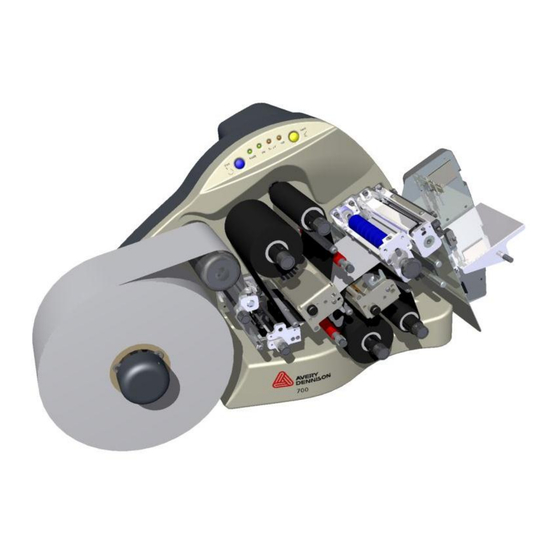
User’s Manual—SNAP™ 700 Printer 3.4 Printer Description 3.4.1 Component Descriptions Shown below are the important parts of the SNAP 700 Printer. Please take a moment to familiarize yourself with the printer. Upper Print Station Control Panel Rotary Knife Assembly Upper Ink Arbors... -
Page 20: Printer Configurations
1 over 1 – The Snap 700 1 over 1 features one upper print head over one lower print head, capable of printing a two sided label. 1 over 0 – The Snap 700 1 over 0 features one print head on top only. Classification: Avery Dennison - Public... -
Page 21: Printer Setup
NOTE: There is a sleeve on the connector that will snap when the connector is fully engaged with the mating connector. The two cables will slide into each other only when the connectors are properly aligned with each other. Classification: Avery Dennison - Public... -
Page 22: Attaching The Unwind Assembly
(Line voltage of 90-132VAC @ 50-60Hz, single phase or 180-265VAC @ 50-60Hz, single phase). The main fuse(s) on the SNAP 700 printers are located inside the AC power entry receptacle on the backside of the printer (see Figure 5). The AC power entry has a fuse drawer that holds the fuse(s) and selects the appropriate line voltage. -
Page 23: Installing The Power Cord
User’s Manual—SNAP™ 700 Printer for your location, you can proceed with setting up your printer. 2. If the line voltage does not match the voltage for your location, contact your local AVERY DENNISON supplier. To change the Fuse Configuration, see Appendix 1. ... -
Page 24: Communications Cable Installation
1. Use either the USB option card if higher download speeds are required for the extra expense of the option, or 2. USB to Serial adapter, if the USB connector is needed and serial download speed is acceptable. Classification: Avery Dennison - Public... -
Page 25: Networking Setup
For GbE Controller set to “ENABLE”. For 82573 Controller set to “ENABLE”. Press F10, the Enter (OK) to save. Restart the printer. 3.7.2 Connecting the networking cable Older motherboards: Network Interface Card Motherboard: Do not use. Classification: Avery Dennison - Public... -
Page 26: Setting The Printer Ip Address
Enter the static IP address as described in section 5.4.2. 5. If moving to another network, set the printer back into DHCP mode. See section 5.4.3 for instructions using the webserver. 6. See section 5.4.4 for troubleshooting tips on the network connection. Classification: Avery Dennison - Public... -
Page 27: Pcmate Platinum Software Installation
3.8 PCMate Platinum Software Installation The software used to drive the AVERY DENNISON family of printers is covered in a separate manual. The PCMate Platinum software is a Windows® application used to create designs for the SNAP 500 printer as well as all other AVERY DENNISON printers. -
Page 28: Selecting The Test Format
Correct the problem and press the Start button again. Repeat this until the printer runs continuously. If you can’t get the printer to run, refer to sections 9 and 10 for troubleshooting. Classification: Avery Dennison - Public... -
Page 29: User's Manual-Snap™ 700 Printer
4.0 Operation 4.1 Loading Supplies Your SNAP 700 printer is designed with upper and optional lower ink supply stations. . The ink supply station setup is dictated by the option of the printer your ordered. There is no way to change this setup at your location. - Page 30 3. Open the print roller (See Figure 8). 4. Pull the ink down and to the right, beneath the turn bar, between the upper print roller and the upper print station, toward the stacker side of the upper ink rewind arbor. Classification: Avery Dennison - Public...
- Page 31 To remove an ink core from the arbor, turn the black knob at the end of the ink arbor counterclockwise and slide the core from the arbor. Save the empty core to be used as the next rewind core. Classification: Avery Dennison - Public...
-
Page 32: Installing Ink To The Bottom Ink Supply Station
Turning the knob clockwise will widen the web guides, while counterclockwise turns will narrow the web guides. The Upper and Lower Print Stations on the SNAP 700 printer are stationary. The rollers swing open and closed for threading and printing. These rollers are held in position for printing with latches on both the inside and outside end of the rollers. - Page 33 11. If the stock will not advance through the knife, refer to Section 5.4.2, Knife Home Position Adjustment. 12. Rotate the stock web guide knob to align it to the stock width. 13. Close the upper and lower print rollers. Classification: Avery Dennison - Public...
-
Page 34: Butt Splice
CAUTION: To prevent damage to the print head, do not use butt splices. The SNAP 700 printer is designed to allow for fast, frequent changing and loading of stock and ink. We recommend re-threading the stock rather than to using a butt splice. If you determine that splicing is faster for threading, tape the ends of the stock together. -
Page 35: Threading Diagrams
User’s Manual—SNAP™ 700 Printer 4.1.5 3.1.5 Threading Diagrams Upper Ink Rewind Upper Ink Unwind Stock Lower Ink Rewind Lower Ink Unwind Threading Diagram Note: Decurler & Web Guide not used on RFID Set-UP Threading Diagram - RFID Classification: Avery Dennison - Public... -
Page 36: Sending A Print Job To The Printer
4.3 Printing Labels 4.3.1 The Control Panel The Control Panel on your SNAP 700 printer is located at the top of the machine. Figure 11 shows the control buttons and lights displayed on the printer. The buttons allow you to control the printer, and the lights indicate the status of the printer. -
Page 37: Printing
4.3.4 Feeding the stock To feed the tape, press and hold the Start/Stop button. After a short delay, the printer will feed tape though the printer. To stop the feed, release the Start/Stop button. Classification: Avery Dennison - Public... -
Page 38: Errors
NOTE: If the error condition no longer exists, the printer will start. It is not necessary to press the Start button twice as is required with previous AVERY DENNISON printer models. If the error continues to recur, contact your local AVERY DENNISON representative. -
Page 39: Using Pre-Printed Stock
The bottom reflective sensor is also standard on the SNAP 700. This sensor is built into the through-hole sensor and will detect a black sense mark printed on the bottom of white tape or tag stock. -
Page 40: Aligning The Sensor To The Stock
When you are in the Option Menu System, you can get out by pressing and holding the Voice button until the printer says “Returning to print mode.” Classification: Avery Dennison - Public... -
Page 41: Running Test Patterns
Voice Button Volume. Appendix 8 contains a flowchart of the Option Menu System. 4.5.1 Running Test Patterns Your SNAP 700 printer offers you two Test Patterns to run before you proceed to production. Test Pattern 1 (Narrow Setup Test Pattern), is a format designed to run on a 2”... - Page 42 8. The voice message will say, “Clearing Current Batch.” The Data light will go out. Figure 12a. Running Test Patterns Test Pattern 2 1. Press and hold the Voice button for about two seconds. The voice message will state, “Press Start for Test Pattern.” Classification: Avery Dennison - Public...
-
Page 43: Setting / Adjusting Voice Button Volume
The procedure for printing test pattern 3 and 4 is the same as described above. 4.5.2 Setting / Adjusting Voice Button Volume The volume level of the voice messages on your SNAP 700 printer is set at Level 3 at the factory. To adjust volume: NOTE: When you select volume setting, the menu will ... - Page 44 If you want to decrease the voice volume to Level 1 or 2, follow Steps 1-7 above and continue to press the Voice button until you reach the desired volume level. Figure 12c. Adjusting Voice Volume Classification: Avery Dennison - Public...
-
Page 45: Making Adjustments
5.0 Making Adjustments 5.1 Print Head Adjustments The print stations on the SNAP 700 printer are stationary. The print rollers swing open for loading stock and ink and are closed when the machine is printing. The rollers are held in the print position with a latch on both the inside and outside end of the rollers. -
Page 46: Adjusting Density (Darkness)
5.2 Adjusting the Stacker The stacker on your SNAP 700 printer is adjustable in four ways: the position of the stacker on the mounting pins, the height of the stack, the angle at which labels are accumulated in the stack, and the angle of the platform. -
Page 47: Stacker Angle
The platform angle can be adjusted in two different locations to alter the angle at which labels are stacked and stopped. 1. Pull the spring loaded Adjustment Pin and move the platform from a horizontal to a backwards angle approximately 20 degrees up on the outer Classification: Avery Dennison - Public... -
Page 48: Static Brush
In general – a light pressure is sufficient to stack well, but long feeds will require slightly more pressure. Keep the static brush parallel to the nip roller mount bracket. Classification: Avery Dennison - Public... -
Page 49: Virtual Control Panel
PCMate Platinum allows the operator to control the printer and make adjustments directly from the PC. The Virtual Control Panel (VCP) shows at the bottom of the PCMate Platinum screen when a SNAP 700 printer is properly connected (see figure 21). Printer Selection Box Batch Control... -
Page 50: Changing Printer Settings In Pcmate
Figure 22a: Virtual Control Panel with Show Setting Window (Firmware 3.35 and below) Figure 22b: Virtual Control Panel (Firmware 3.36 and PCMate 7.6 and above) showing the adjustments available across the width of the printer. Classification: Avery Dennison - Public... -
Page 51: Print/Cut Adjust Tab
NOTE: Don’t use print and cut adjusts to “fine-tune” a format. Rather correct any print position problems in the format and use these adjustments to correct printer variation only. Otherwise, you have to adjust each format before printing. Classification: Avery Dennison - Public... -
Page 52: Selecting The Printer Language
5.3.5 Setting the Date and Time The SNAP 700 printer has a built-in clock and calendar. You may change the date and time as follows: In the Virtual Control Panel, click on the Options Tab. The current printer date and time is shown. -
Page 53: Enabling Or Disabling The Cutter
5 ips (the third speed in the printer’s speed list of 3, 4, and 5 ips), the SNAP 700 printer would use 6 ips, which is the third speed in its speed list of 3, 4.5, 6, and 7 ips. -
Page 54: Selecting The Sense Mark Type
Its main purpose is to allow you to activate the optional Contrast Sensor, since older formats or formats for other AVERY DENNISON printers will not have the Contrast Sensor type. This option is set in the same way as Print Speed. -
Page 55: Viewing The Life Counts
User’s Manual—SNAP™ 700 Printer 5.3.11 Viewing the Life Counts The SNAP 700 printer maintains a count of the total number of labels printed, and the total number of inches of material. Also, there is a resettable label counter. In the Virtual Control Panel, the Life Counts can be found in the Life Counts/Software Version tab. -
Page 56: Print Quality
Files – lists files stored on the printer. This can help determine in the printer has a font installed. Diagnostics – Test various printer components by running Interactive SNAP Diagnostics. You can also view the Error Log File. Classification: Avery Dennison - Public... -
Page 57: Web Server
Enter the printer’s IP address in the address bar and press Enter. The following window will appear: The values shown are the current printer settings. To change the settings, click the “Configure” button. The following window will appear: Classification: Avery Dennison - Public... -
Page 58: Converting The Dhcp Address To A Static Address
Static address” button. At this time, the IP address is set to the static address and the web server will no longer be available. Enter the new IP address in a new browser window. Classification: Avery Dennison - Public... -
Page 59: Resetting The Printer To Dhcp Mode
198.1.63.123” <Enter>. 10. The ping command will try to contact the printer four times. If there is a problem with the connection, the result will be “Request timed out” 11. A successful ping looks like this Classification: Avery Dennison - Public... -
Page 60: Maintenance
Wear anti-static gloves at all times when handling print heads to prevent oils on your hands from contaminating the print head. The SNAP 700 printer optional spare parts kit Classification: Avery Dennison - Public... -
Page 61: Cleaning Procedures
CAUTION: AVERY DENNISON recommends Master Cleaning Kit #921341K for use in cleaning print heads. 1. Before cleaning any part of your SNAP 700 printer, turn off the power to the printer.To avoid damaging the print head, wear the anti-static wrist strap (which must be in contact with the skin and be tight). -
Page 62: Print Head Replacement
5. Fasten the clip end of the anti-static wrist strap to a metal portion of the printer (usually the stacker) to prevent static from your skin from entering the print station. Clip Springs for Print Head release Print head Cable Connector(s) Classification: Avery Dennison - Public... - Page 63 Figure 17b. Print Head released from Cable springs Print Head Assembly – Figure 17c. Figure 17d. Inserting Print Head Removed Assembly 9. Place the new print head assembly onto the print station (see Fig. 17c and Classification: Avery Dennison - Public...
- Page 64 Options tab and set appropriate head category. Click the Apply Settings button to return to PCMate Platinum. 17. As a final test, make a test run to check the print quality of the labels. Classification: Avery Dennison - Public...
-
Page 65: Lubrication
6.4 Rotary Knife Assembly The rotary knife assembly for the SNAP 700 printer is fastened directly to the frame. It has been designed to deliver an average of two million cuts if used with woven tapes and four million cuts when used with coated tapes, provided no foreign objects are inserted into the assembly that could damage the knife blades. -
Page 66: Removing And Replacing The Knife Assembly
3/32” allen key. Do not change the setting of the shear adjustment. Remove the end cap and used blades by sliding the end cap out of the “U” shaped holder. Note the location of the pressure spring to reassemble the Classification: Avery Dennison - Public... - Page 67 Caution: Do not mix new and used knife blades as they will cause premature ware and shorten their life. A chip or a nick in the blades may damage a new blade on start up. Gold Spring Light Blue Spring Classification: Avery Dennison - Public...
- Page 68 21. Turn on the power to the printer and allow the knife to return to home position. 22. Rethread the stock through the Auxiliary Feed, Nip Roller, and knife. Classification: Avery Dennison - Public...
-
Page 69: Adjust The Knife Home Position
1. 05624097 – Assembly, Feed Roller 2. 05625014 – Roller, Molded Platen, Red 3. 05624024 – Roller, Nip Drive, Molded Failure to replace these rollers as suggested above may result in poor print quality, tracking and feed issues. Classification: Avery Dennison - Public... -
Page 70: Service Adjustments
If the stock will not advance through the Knife, check to be sure the knife is in the home position (see Sect. 5.4.2, Knife Home Position Adjustment). Classification: Avery Dennison - Public... -
Page 71: Knife Shear Adjustment
Right Set Screw Pivot Screw Figure 19a. Loosening Outer Pivot Screw Figure 19b. Adjusting Right Set Screw Left Set Screw Knife Rotation Figure 19c. Adjusting Left Set Screw Figure 19d. Manual Rotation of Knife Shaft Classification: Avery Dennison - Public... - Page 72 9. If the two parts of the material are still attached by thread, the knife is damaged and must be replaced. 10. If your test only cuts the material part way through, an additional adjustment is required. 11. Retest and repeat Steps 9 and 10 above. Classification: Avery Dennison - Public...
-
Page 73: Upgrading The Printer Firmware
8.1 Introduction The SNAP 700 printer firmware can be updated electronically using “UPG” files received from Avery Dennison. A “UPG” file is a software file with “.upg” as an extension. Files are either “zip” files, which must be extracted/unzipped, or UPG files. -
Page 74: Getting Upg File Without Using D2Comm
2. Under “Products and Services” click “Utilities and Firmware” 3. Next under “Apparel Model Search” (2 one down), click “SNAP 700” 4. Choose one of 3 upgrade files. For example, for version 3.36: a. V336_15_10.zip – This is the complete upgrade and includes English and all alternate language messages and prompts b. -
Page 75: Upgrading Through Pcmate
PCMate Platinum. Each time you start PCMate Platinum, this screen will appear until you either perform the upgrade or remove it (see below). 4. When you click on the Yes button, the following screen will appear. Classification: Avery Dennison - Public... - Page 76 The upgrade process can take quite a while. If the process is interrupted, the printer will attempt to revert to the last revision. If it fails, it will revert to a safe version. If this occurs, it will be necessary to redo the upgrade. Classification: Avery Dennison - Public...
- Page 77 The top progress bar shows the file being sent, while the bottom bar shows the overall progress. 8. Once the files are on the printer, the following window will appear. Do not click on any buttons until the upgrade finishes. Classification: Avery Dennison - Public...
-
Page 78: Upgrading Through Usb Flash Drive
4. When the printer is turned on, it will detect the USB flash drive and upgrade the printer automatically. 5. This process takes approximately 4-5 minutes. Some older operating systems do not support this function. If you try it and it doesn’t work, you must upgrade using PCMate. Classification: Avery Dennison - Public... -
Page 79: Upgrading Through The Webserver
(Avery) and password (Dennison) in the corresponding boxes, and click the Quickconnect button. 3. The screen is divided into two sets of panes. The left panes show folders on the computer, and the right panes show folders on the printer. The top pane on each Classification: Avery Dennison - Public... - Page 80 There may be a folder in the root directory of the printer called PAXA. This is a temporary folder used in processing the upgrade file. Ignore this directory and place the upgrade file in the root directory. Classification: Avery Dennison - Public...
- Page 81 If you refresh the browser window during the upgrade process, you will receive an error message that the connection has timed out or the web page is unavailable. Simply refresh again until the web page appears. Classification: Avery Dennison - Public...
-
Page 82: Electrical Troubleshooting
1) Connect a standard PC monitor and or “Hardware error 2, keyboard to the printer and follow the printer requires service” instructions found in the Engineering or “BIOS corrupted, Bulletin “06_015_500_BIOS_Revised.doc” replace the mother to reset the BIOS settings. Classification: Avery Dennison - Public... - Page 83 1) Flash Disk Failure 1) Replace Flash Disk Module or “Hardware error three” during power up. Printer requires service. Corrupted safe operating system. Replace the flash disk”. (Message depends on software version.) 2) Motherboard Failure 1) Replace motherboard Classification: Avery Dennison - Public...
- Page 84 DENNISON PCL printer as per your PCMate Platinum manual. 6) Faulty Mother Board 1) Replace the Mother Board. IF THE RECOMMENDED CORRECTIVE ACTIONS DO NOT RESOLVE THE PROBLEM (S), CONTACT YOUR LOCAL AVERY DENNISON REPRESENTATIVE. Classification: Avery Dennison - Public...
-
Page 85: Stock / Ink Advance
3) Stock is bound. 1) Remove and rethread the stock. 4) Ink is bound. 1) Remove and rethread the ink. IF THE RECOMMENDED CORRECTIVE ACTIONS DO NOT RESOLVE THE PROBLEM (S), CONTACT YOUR LOCAL AVERY DENNISON REPRESENTATIVE. Classification: Avery Dennison - Public... -
Page 86: Print
3) Stock Arbor is not tight. 1) Check and adjust as needed. Refer to section 3.1 Loading Supplies. IF THE RECOMMENDED CORRECTIVE ACTIONS DO NOT RESOLVE THE PROBLEM (S), CONTACT YOUR LOCAL AVERY DENNISON REPRESENTATIVE. Classification: Avery Dennison - Public... - Page 87 1) Set print head pressure. Refer to section pressure. 4.1.1, Adjusting Print Head Pressure. 5) Worn printer roller. 1) Contact your local AVERY DENNISON representative. IF THE RECOMMENDED CORRECTIVE ACTIONS DO NOT RESOLVE THE PROBLEM (S), CONTACT YOUR LOCAL AVERY DENNISON REPRESENTATIVE.
-
Page 88: Cut / Stack
Knife will not cut. 1) Knife blades are dull. 1) Refer to section 5.4.1, Removing and Replacing the Knife assembly. IF THE RECOMMENDED CORRECTIVE ACTIONS DO NOT RESOLVE THE PROBLEM (S), CONTACT YOUR LOCAL AVERY DENNISON REPRESENTATIVE. Classification: Avery Dennison - Public... -
Page 89: Printer Errors
Check the printhead connections. If the error still occurs, change the printhead. If the error still occurs, replace the printhead cable. If the error still occurs, replace the MCB. Classification: Avery Dennison - Public... - Page 90 MCB BAD STACK ERROR continues to occur, report the error and the MCB KNF FLIT TBL TOO circumstances that cause it to Avery Dennison Service. These errors are caused by errors in the MCB KNIFE STATE TOO software and are not caused by hardware failures.
- Page 91 If the format does not specify a bottom reflective sense mark, the sensor type override may be set. Classification: Avery Dennison - Public...
- Page 92 This error indicates that the printer could not calibrate the sensor. Possible causes are misalignment of the sensor to the sense mark or incorrect sensor type Classification: Avery Dennison - Public...
- Page 93 The printer checks to make sure the software software versions are versions within the printer are compatible. This error not compatible indicates that the versions are not compatible. Upgrade to the latest operating system software. Classification: Avery Dennison - Public...
- Page 94 This will also reset all the printer settings (print and cut adjust, baud rate, cutter enable, etc.) to their default values. IF THE RECOMMENDED CORRECTIVE ACTIONS DO NOT RESOLVE THE PROBLEM (S), CONTACT YOUR LOCAL AVERY DENNISON REPRESENTATIVE. Classification: Avery Dennison - Public...
-
Page 95: Mechanical Troubleshooting
1) Be sure the nip roller is free to rotate and moves easily in the bearing slots. Check for a loose drive gear. IF THE RECOMMENDED CORRECTIVE ACTIONS DO NOT RESOLVE THE PROBLEM (S), CONTACT YOUR LOCAL AVERY DENNISON REPRESENTATIVE. Classification: Avery Dennison - Public... -
Page 96: Ink
1) Knife blades are dull. 1) Refer to section 5.4.1, Removing and of the knife. Replacing the Knife Assembly. IF THE RECOMMENDED CORRECTIVE ACTIONS DO NOT RESOLVE THE PROBLEM (S), CONTACT YOUR LOCAL AVERY DENNISON REPRESENTATIVE. Classification: Avery Dennison - Public... -
Page 97: Stacker
2) Loose set screw or drive gear - Tighten 3) Soft material / narrow web 1) Adjust the height of the static brush hitting static brush IF THE RECOMMENDED CORRECTIVE ACTIONS DO NOT RESOLVE THE PROBLEM(S), CONTACT YOUR LOCAL AVERY DENNISON REPRESENTATIVE. Classification: Avery Dennison - Public... -
Page 98: Appendices
11.0 Appendices 11.1 Fuse Configuration The main fuse(s) on the SNAP 700 are located inside the AC power entry receptacle. The entry has a fuse drawer that holds the fuse(s) and selects the appropriate line voltage. If the number in the window DOES NOT match the AC line voltage intended to be supplied to the printer, DO NOT plug the power cord in. -
Page 99: Ink And Stock Transfer Types
4002NWT Fabric & XC-3111 (UK) 4002NWT Fabric & HR-1111 (UK) G.S. Satin & XC-3111 (UK) 2012T Fabric & XC-3111 (UK) 1021T Fabric & XC-3111 (UK) 2800 Fabric & CT-1111 591SST Fabric & CT-1111 Ink 591SST/601SST Fabrics & CT-1114 Ink Classification: Avery Dennison - Public... - Page 100 4800TST Fabric & HS1111 770SWT Fabric & CT1112 770SWT Fabric & CT1114 770SWT Fabric & CT1115 770SWT Fabric & CT5137 772SWT Fabric & CT1112 772SWT Fabric & CT1114 772SWT Fabric & CT1115 772SWT Fabric & CT5137 Classification: Avery Dennison - Public...
-
Page 101: Printer Specifications
Also support for blank or pre-printed card stock, coated or uncoated, up to 10 point - as well as pressure sensitive labels. Supply Roll: 3” ID (76 mm) cardboard core, Maximum roll size 11.5” O.D. (29 cm) Classification: Avery Dennison - Public... - Page 102 Ink Ribbon AVERY DENNISON standard thermal colors and widths AVERY DENNISON white plastic core: Maximum Ink O.D. 3.5” Ink widths: With Metric Adapter - 25mm to 127mm metric widths in 5mm increments. With Inch Adapter - 1” to 5” inch widths in ¼” increments.
-
Page 103: Factory / Field Installation Of Top Sensor Assemblies
Replace with the Slotted Web Turn Shaft so that the larger slot is in the upper position as shown. Install the ¼-20 x 3/8 Button Head Cap Screw on the end of the shaft. Slotted Web Turn Shaft ¼-20 x 3/8 BHCS Replace Turn Shaft Classification: Avery Dennison - Public... - Page 104 6. From the back of the Upright Frame, slide the Collet / Cable Assembly through the ¾ diameter hole and secure with (2) 10-32 x 3/8 Button Head Screws. 10-32 X 3/8 Button Head Screws Classification: Avery Dennison - Public...
- Page 105 User’s Manual—SNAP™ 700 Printer 7. Install the “O”-Ring in the front groove behind the Fiber-Optic Tube. (See pics below for clarity) Classification: Avery Dennison - Public...
- Page 106 11. Assemble the Sensor / Bracket / Lead Assembly to the Upright Frame using (2) Pem Nuts shown above. Use 10-32 x ¼ Button Head Screws supplied with kit. 12. Assemble Sensor Power Cable to Sensor and plug into MCB Connector labeled “Option Top Color / Contrast”. Classification: Avery Dennison - Public...
-
Page 107: Programming The Contrast Sensors
Sensor. 11.5 Programming the Contrast Sensors There are two optional contrast sensors available for the SNAP 700 printer. 620006-1 is the standard contrast sensor. It works well in most situations where there is significant contrast between the material background and the sense mark. In situations where there is less contrast between the material and the sense mark, or the material and sense mark are of similar colors, the 620007-1 Color Contrast Sensor may be required. -
Page 108: Programming The Contrast Sensor
Move the material so that the sense mark moves back and forth under the sensor. The Q light on the sensor should flash when the sense mark passes under the sensor. Classification: Avery Dennison - Public... -
Page 109: Programming The Color Contrast Sensor
Move the material so that the sense mark moves back and forth under the sensor. The Q/ok light on the sensor should flash when the sense mark passes under the sensor. Classification: Avery Dennison - Public... - Page 110 991305 O-Ring, 5/16 x ½ x .032 Wall 990134 ¼-20 x 3/8 BHCS 620006D Instructions, Top Color / Contrast Sensor 990090 10-32 x 3/8 BHCS *620006 use part no. 581181 *620007 use part no. 581182 Classification: Avery Dennison - Public...
-
Page 111: Factory / Field Installation Of High Speed Verifier Assembly
Install the Bracket, Verifier Upright onto the Base Bracket with (2) 8-32 x 3/8 Flat Head Screws. Tighten securely. 621304 – Bracket, Verifier Upright 990083 – 10-32 x ¾ SHCS 990055 – 8-32 x 3/8 FHCS 621303 – Bracket, Verifier, Mount Base Classification: Avery Dennison - Public... - Page 112 (2) 6-32 x 3/8 Cap Screws (990016). 991204 – Knob 621307A – Bracket, Verifier Mount 989979 – 10-32 x 1 Set Screw 990102 – #10 SAE Washer 551144 – Verifier 990016 – 6-32 x 3/8 SHCS Classification: Avery Dennison - Public...
-
Page 113: Installation Procedure - Electrical
3) Mount J1 (5 wire, 10 pin connector) to MCB J7. Mount J2 (3 wire, 10 pin connector) to MCB J11. 4) Assemble External Verifier Lead Connector to mating Connector in internal cable (installed in step 2) & mating Connectors to top of Verifier. Classification: Avery Dennison - Public... -
Page 114: Installation - Rear Cover
2) Scribe a line around the inner cutout of the Template. 3) Remove the Template and with a small saw or Dremel Tool, remove the material within the scribed line. Slide the Cover onto the Printer to assure a clearance around the Verifier Bracket. Classification: Avery Dennison - Public... -
Page 115: Warranty Policy
Consumable elements are not covered. Consumable elements are those that show normal wear from typical equipment usage including, without limitation, printheads, knives, rollers in contact with the web, and sonic units. Avery Dennison reserves the right to determine which elements are defined as “consumable.”... -
Page 116: Service
Americas (United States, Canada, Mexico, Central America, Caribbean Region, and South America excluding Brazil). Outside the US, the local Avery Dennison office is responsible for equipment and parts warranty. Customers must ensure coverage during machine purchase. Equipment purchased and exported to regions outside local Avery Dennison office coverage are not covered by warranty. -
Page 117: Option Menu System Flowchart
1 AND RETURNS TO LEVEL 2 AND RETURNS 3 AND RETURNS TO TO PRINT MODE. PRINT MODE. TO PRINT MODE. PRINT MODE. PRINT MODE. RETURNING TO PRINT MODE. RETURNS TO PRINT MODE. VOICE OPTION MENU NAVIGATION CHART Classification: Avery Dennison - Public... -
Page 118: Electrical Drawings
User’s Manual—SNAP™ 700 Printer 12.0 Electrical Drawings Classification: Avery Dennison - Public... -
Page 119: Electrical System Schematic
User’s Manual—SNAP™ 700 Printer 12.1 Electrical System Schematic For RFID Printer 621107RFID TM Classification: Avery Dennison - Public... -
Page 120: Harness Connections
S1 CONTRAST POT - J31 OPTIONS OPTION - J35 VERIFIER - J7 (RFID - J11) USER INTERFACE OPTIONAL FRONT PANEL - J10 MINI FRONT PANEL - J5 MOTHER BOARD MB RESET - J22 MOTHER BOARD AUDIO - J37 Classification: Avery Dennison - Public... -
Page 121: Mechanical Assembly Drawings
User’s Manual—SNAP™ 700 Printer 13.0 Mechanical Assembly Drawings Classification: Avery Dennison - Public... -
Page 122: Unwind Assembly
User’s Manual—SNAP™ 700 Printer 13.1 Unwind Assembly Classification: Avery Dennison - Public... - Page 123 6-32 E-S NUT 05623012 SUPPORT, OUTER UNWIND 05583006 KNOB, UNWIND 05990052 8:32 X 1/2 CAP SCREW 05593003 HUB, INNER 05634051 SHAFT, QUICK ATTACH UNWIND 05996311 4 SCREW, 4-40 X 5/8 PPHS W/ EXT TOOTH LOCK WASHER Classification: Avery Dennison - Public...
-
Page 124: Unwind Assembly Rfid 3" / 4
User’s Manual—SNAP™ 700 Printer 13.2 Unwind Assembly RFID 3” / 4” Classification: Avery Dennison - Public... - Page 125 ADAPTER, 4" HUB 05623010 RING, UNWIND HUB 05990028 6:32X3/8 SOCKET F.HD. SCREW 05623011 SPRING CLAMP 05990019 6:32X1/4 B.H. SCREW 05634051 SHAFT, QUICK ATTACH UNWIND 05996311 4 SCREW, 4-40 X 5/8 PPHS W/ EXT TOOTH LOCK WASHER Classification: Avery Dennison - Public...
-
Page 126: Unwind Motor Assembly
User’s Manual—SNAP™ 700 Printer 13.3 Unwind Motor Assembly Classification: Avery Dennison - Public... - Page 127 05991510 BALL BEARING, 16MM OD X 8 MM ID FLG 117954 GEAR-RIBBON 75T 05990327 SNAP RING, 5/16 "E" RING 117955 GEAR-RIBBON 54T-15T 05991367 E-RING, 9/64 05581186 MOTOR, STOCK UNWIND W/EXTENSION 05991639 M2.6 X 4mm PPHS Classification: Avery Dennison - Public...
-
Page 128: Decurler Assembly
User’s Manual—SNAP™ 700 Printer 13.4 Decurler Assembly Classification: Avery Dennison - Public... - Page 129 DESCRIPTION 05624012 SHAFT, DECURLER 05991376 10-32 X 1/2 PAN PHILLIPS 117903 BEARING-PLATEN 05594011 ROLLER, DECURLER 05990327 SNAP RING, 5/16 "E" RING 05990067 WASHER, #8 SAE 05991379 10-32 X 3/8 PHPS 05991516 PLUG, 5/8 DIA HOLE Classification: Avery Dennison - Public...
-
Page 130: Web Guide Assembly
User’s Manual—SNAP™ 700 Printer 13.5 Web Guide Assembly Classification: Avery Dennison - Public... - Page 131 ASSY, WEB GUIDE MOUNT 05624050 SHAFT, WEB ADJUST 05990325 SNAP RING, 3/16 "E" RING 05196028 KNOB, BLACK (GLOSS) .187 SHAFT HOLE BUSHING SOCKET SET SCREW 05624049 WEB GUIDE, REAR 05624047 WEB GUIDE, FRONT 05990484 1/4:20X1/2 NYLON SLOTTED SCREW Classification: Avery Dennison - Public...
-
Page 132: Sensor Tray Assembly
User’s Manual—SNAP™ 700 Printer 13.6 Sensor Tray Assembly Classification: Avery Dennison - Public... - Page 133 KNOB, BLACK (GLOSS) .187 SHAFT 05196028 HOLE BUSHING SOCKET SET SCREW 05624044 BRIDGE BLADE, BOTTOM 05990055 8:32X3/8 F. H. SCREW 05990066 8:32X1/4 BTN. SCREW 05624030 BLOCK, LED MOUNT 05581128 SENSOR, REFLECTIVE HARNESSED 05989985 WASHER, #2 SAE Classification: Avery Dennison - Public...
-
Page 134: Sensor Tray Rfid Assembly
* Items 1 and 4 ordered as one Assembly, Part no. 05624087 – Assy, Rear Support **Items 3 and 4 ordered as one Assembly, Part no. 05624088 – Assy, Front Support Parts shown exploded for clarity purposes Classification: Avery Dennison - Public... - Page 135 SHAFT, WEB TURN, STACKER MOUNT 126547 (REPLACES 126354) 5990133 1/4:20 X 3/4 F H SCREW 5624064 SPACER, RFID ANTENNA 5990374 COLLAR, 1/2" 5991074 3 X 12MM FLAT HEAD SCREW 5990484 1/4:20X1/2 NYLON SLOTTED SCREW 125731 BOX, ANTENNA Classification: Avery Dennison - Public...
-
Page 136: Top Print Head Assembly
User’s Manual—SNAP™ 700 Printer 13.8 Top Print Head Assembly * Items 26 and 27 are not required on the RFID Printer Classification: Avery Dennison - Public... - Page 137 6:32 X 1/2 BUTTON HEAD SCREW 05990051 8:32 X 3/8 CAP SCREW 05990513 TIE WRAP, TY523M SMALL 05991597 SPRING, EXT 05625010 TURN BAR, INK 05990055 8:32X3/8 F. H. SCREW 05621124 CABLE, PRINT HEAD 700, BOTTOM Classification: Avery Dennison - Public...
-
Page 138: Bottom Print Head Assembly
User’s Manual—SNAP™ 700 Printer 13.9 Bottom Print Head Assembly Classification: Avery Dennison - Public... - Page 139 6:32 X 1/2 BUTTON HEAD SCREW 05990051 8:32 X 3/8 CAP SCREW 05990513 TIE WRAP, TY523M SMALL 05991597 SPRING, EXT 05625010 TURN BAR, INK 05990055 8:32X3/8 F. H. SCREW 05621124 CABLE, PRINT HEAD 700, BOTTOM Classification: Avery Dennison - Public...
-
Page 140: Print Head Assembly
User’s Manual—SNAP™ 700 Printer 13.10 Print Head Assembly Classification: Avery Dennison - Public... - Page 141 User’s Manual—SNAP™ 700 Printer Printhead Assembly Parts List ITEM PART NO. DESCRIPTION 05625094-1 ASSEMBLY, 700 PRINT HEAD, 5 INCH 05625050 GUARD, PRINT HEAD Classification: Avery Dennison - Public...
-
Page 142: Platen Roller Assembly
User’s Manual—SNAP™ 700 Printer 13.11 Platen Roller Assembly Classification: Avery Dennison - Public... - Page 143 SHAFT, PLATEN ROLLER 05625046 SPACER, SWING ARM GUIDE 05990327 SNAP RING, 5/16 "E" RING 05625014 ROLLER, MOLDED, PLATEN, RED 05990067 WASHER, #8 SAE 05990068 WASHER, #8 LOCKWSAHER 05991454 8-32 X 1/4 THUMB SCREW 05991608 SPRING, EXTENSION Classification: Avery Dennison - Public...
-
Page 144: Ink Arbor Assembly
User’s Manual—SNAP™ 700 Printer 13.12 Ink Arbor Assembly Classification: Avery Dennison - Public... - Page 145 SHAFT, ADJUSTMENT 05991543 FOIL KNOB, G-12 05990058 8-32 X 1/4 KNURLED CUP POINT 05626011 CORE STOP, FRONT 05626012 CORE STOP, REAR 05990057 8-32 X 1/8 KNURLED CUP POINT 05991567 SCREW, 8-32 X 3/16 NYLON SET SCREW Classification: Avery Dennison - Public...
-
Page 146: Ink Unwind / Rewind Motor(S) Assembly
User’s Manual—SNAP™ 700 Printer 13.13 Ink Unwind / Rewind Motor(s) Assembly Classification: Avery Dennison - Public... - Page 147 User’s Manual—SNAP™ 700 Printer Ink Unwind / Rewind Motor(s) Assembly Parts List ITEM PART NO. DESCRIPTION 05621237 KIT, FRAME ASSEMBLY, SNAP 700 05991510 BALL BEARING, 16MM OD X 8 MM ID FLG 05626088-1 ASSEMBLY, INK ARBOR SHAFT 117954 GEAR-RIBBON 75T 05990327 SNAP RING, 5/16 "E"...
-
Page 148: Drive Assembly
User’s Manual—SNAP™ 700 Printer 13.14 Drive Assembly Classification: Avery Dennison - Public... - Page 149 05990066 8:32X1/4 BTN. SCREW 05990079 10:32 X 1/4 CAP SCREW 05624046 BRACKET, STRIPPER UPPER 05624178 COVER, FEED GUARD, SNAP 700 05624015 BRACKET, BASE, DRIVE MODULE 05991626 COMPRESSION SPRING, .360 OD X .059 WIRE X .69 Classification: Avery Dennison - Public...
-
Page 150: Knife Assembly
Items 5 & 7 ordered as a kit only, includes both torsion springs items 18 & 19. Parts shown exploded for clarity purposes * See Addendum II for Knife Parts List of machines with short feed option* Classification: Avery Dennison - Public... -
Page 151: Knife Assembly Parts List
SCREW, 6-32 BUTTON HEAD CS X 3/16 05357095 ASSEMBLY, OILER MOUNT 05990055 8:32X3/8 F. H. SCREW 05197319 TORSION SPRING,RIGHT 05357029 TORSION SPRING BACK, DC KNIFE 05990025 6:32 X 1/4 SET SCREW 05990120 1/4:20 X 1/2 CAP SCREW Classification: Avery Dennison - Public... -
Page 152: Nip Roller Assembly
User’s Manual—SNAP™ 700 Printer 13.16 Nip Roller Assembly * See Addendum II for Nip Roller Parts List of machines with short feed option* Classification: Avery Dennison - Public... - Page 153 SPRING, COMP 500/600 NIP ASSEMBLY 05990424 4-40 X 3/8" SH CAP SCREW 05624038 BRACKET, STRIPPER 05448010 STATIC BRUSH 05991373 8-32 X 1/4 PAN PHILLIPS 05991454 8-32 X 1/4 THUMB SCREW 05991377 10-32 X 3/4 PAN PHILLIPS Classification: Avery Dennison - Public...
-
Page 154: Knife / Drive Motors Assembly
User’s Manual—SNAP™ 700 Printer 13.17 Knife / Drive Motors Assembly Classification: Avery Dennison - Public... - Page 155 05991642 DRIVE, BEAM COUPLING 05587018 ASSEMBLY, KNIFE DRIVE SHAFT 05581130 SENSOR, OPTICAL SLOTTED, HARNESSED 05585016 GEAR, 38T DRIVE 300 DPI 05991422 4-40 X 1/4 PAN HD PHILLIPS 05990006 4:40 X 1/4 CAP SCREW 117902 GEAR-PLATEN Classification: Avery Dennison - Public...
-
Page 156: Knife Drive Motor Assembly Rfid
User’s Manual—SNAP™ 700 Printer 13.18 Knife Drive Motor Assembly RFID Classification: Avery Dennison - Public... - Page 157 10:32X1/2 CAP SCREW 05627030 DRIVE, BEAM COUPLING, ALTERED 05587018 ASSEMBLY, KNIFE DRIVE SHAFT 05581130 SENSOR, OPTICAL SLOTTED, HARNESSED 05991422 4-40 X 1/4 PAN HD PHILLIPS 05627031 SHAFT, INERTIAL SLUG 05990077 8:32 X 1/2 KNURLED CUP POINT Classification: Avery Dennison - Public...
-
Page 158: Rfid Reader Assembly
User’s Manual—SNAP™ 700 Printer 13.19 RFID Reader Assembly Classification: Avery Dennison - Public... - Page 159 RFID Reader Assembly Parts List ITEM PART NO. DESCRIPTION 05591141 POWER SUPPLY, 24V HARNESSED 05621023-1 BRACKET, SIRIT / THINGMAGIC 05999787 4M 8MM SHCS 129383 MODULE, UHF RFID, THINGMAGIC M5E-C 05991422 4-40 X 1/4 PAN HD PHILLIPS Classification: Avery Dennison - Public...
-
Page 160: Covers Assembly
User’s Manual—SNAP™ 700 Printer 13.20 Covers Assembly Classification: Avery Dennison - Public... - Page 161 User’s Manual—SNAP™ 700 Printer Covers Assembly Parts List ITEM PART NO. DESCRIPTION 05621237 KIT, FRAME ASSEMBLY, SNAP 700 05621202A COVER, FRONT, 700 SNAP 1/1 05581205 COVER, REAR, 500 05991376 10-32 X 1/2 PAN PHILLIPS 05991508 8-32 X 1/2 FLANGED BUTTON HEAD SCREW 05341210 FEET, 1 1/2"...
-
Page 162: Cooling Fans Assembly
User’s Manual—SNAP™ 700 Printer 13.21 Cooling Fans Assembly Classification: Avery Dennison - Public... - Page 163 User’s Manual—SNAP™ 700 Printer Cooling Fans Assembly Part List ITEM PART NO. DESCRIPTION 05621237 KIT, FRAME ASSEMBLY, SNAP 700 05621206-2 BRACKET, MCB SUPPORT 05621007 BRACKET, EXIT FAN CHUTE 05991372 6-32 X 1/4 PAN PHILLIPS 05621004 BRACKET, EXIT FAN MOTOR 05621134...
-
Page 164: Stacker Assembly (Sheet 1 Of 2)
User’s Manual—SNAP™ 700 Printer 13.22 Stacker Assembly (Sheet 1 of 2) Classification: Avery Dennison - Public... - Page 165 SPRING, PIN LOCK 05996159 SWITCH ROCKER, SPDT 05989986 4-40 ES NUT HARNESS, DOWN STACKER ASSY, PROGRAMMED WITH 05581177 GEAR 05628033-1 COVER, DOWN STACKER, 700 05991442 8-32 X 3/8 PHILLIPS FLAT HEAD SCREW 05628012 SPACER, STACKER SLIDE Classification: Avery Dennison - Public...
-
Page 166: Stacker Assembly (Sheet 2 Of 2)
User’s Manual—SNAP™ 700 Printer 13.23 Stacker Assembly (Sheet 2 of 2) Classification: Avery Dennison - Public... - Page 167 SPRING, PIN LOCK 05991442 8-32 X 3/8 PHILLIPS FLAT HEAD SCREW 05996159 SWITCH ROCKER, SPDT 05628011 CHAIN, STACKER DRIVE 05991510 BALL BEARING , 16mm O.D. x 8mm I.D. FLG 05628012 SPACER, STACKER SLIDE 05628002 SHAFT, MAIN DRIVE Classification: Avery Dennison - Public...
- Page 168 User’s Manual—SNAP™ 700 Printer Page intentionally left blank Classification: Avery Dennison - Public...
-
Page 169: Addendum I - Handling Procedures
PRINTER WEIGHT: The printer weighs are 75 pounds (34 Kg) or less and requires a table of sufficient quality and strength to handle this load. The AVERY DENNISON SNAP® printer line requires an area with the approximate dimensions of 72" wide x 30" deep x 32" high (1.8 m x 76 cm x 81 cm). The host PC (if used) and any printer options will increase the required area. - Page 170 The information contained herein is believed to be reliable but AVERY DENNISON makes no representations concerning the accuracy or correctness of the data. This product, the related media and supplies, like any other should be tested by the customer/user thoroughly under end user conditions to ensure the product meets the particular requirements.
-
Page 171: Addendum Ii - Short Feed
"O" RING BELT RUBBER ROLLER RUBBER ROLLER "O" RING BELT NOTE: "O" RING BELTS SHOWN STATIC BRUSH LOOSE FOR CLARITY. WHEN INSTALLING BELTS, THEY WILL BE TIGHT WHEN STRETCHED. THUMB SCREW BRIDGE BLADE NIP ROLLER BRACKET Classification: Avery Dennison - Public... -
Page 172: Short Feed Assembly
User’s Manual—SNAP™ 700 Printer 15.1.2 Short Feed Assembly 2 33 11 11 32 26 30 26 30 Classification: Avery Dennison - Public... -
Page 173: Short Feed Assembly Part List
8-32 X 1/4 BHCS 05991253 6-32 X 3/16 BHCS 05991454 8-32 X 1/4" THUMB SCREW 05991523 SPRING, COMP 500/600 NIP ASSEMBLY 05991651 6-32 X 7/8 BHCS 05999001 R6FF BEARING 05999097 BUSHING, FL 1/4 X 3/8 X 3/16 Classification: Avery Dennison - Public... - Page 174 Re-adjustment required externally to part. function. Missing Electrical part, machine won’t Part fell off or disconnected, put back on, still function. good. Missing mechanical part, machine Missing Supplies or Formats won’t function. Description of Failure Classification: Avery Dennison - Public...
-
Page 175: Revision Record
Added support for RFID printers in the parts pages Added updates to many of the parts pages for the latest production parts Updated text to support both SNAP 700 and SNAP 700 RFID Added addendum for Printer and Supplies Handling. - Page 176 User’s Manual—SNAP™ 700 Printer 028028 Avery Dennison 170 Monarch Lane Miamisburg, OH 45342 1-800 543-6650 (In the U.S.A.) 1-800-387-4740 (In Canada) www.averydennison.com Classification: Avery Dennison - Public...
Need help?
Do you have a question about the snap 700 and is the answer not in the manual?
Questions and answers