Table of Contents
Advertisement
Quick Links
Advertisement
Table of Contents

Related Manuals for Keysight N9340B


Summary of Contents for Keysight N9340B
- Page 1 Keysight Technologies N9340B Handheld Spectrum Analyzer Demo Guide...
- Page 2 This demo guide is a tool for the new user to gain familiarity with the basic functions and features of the Keysight Technologies, Inc. N9340B handheld spectrum analyzer. Almost all exercises utilize a signal from an external signal generator with amplitude of –10 dBm and frequency of 100 MHz.
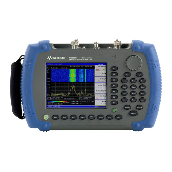
- Page 3 Section 1 Panel Tour Caption Function Power switch Toggles the analyzer between on and off Function keys Includes hardkeys: SYS, FREQ, SPAN, AMPTD, BW/SWP, TRACE, MEAS, and MODE Preset Returns the analyzer to a known state, also turns on/off power save feature (press for 1 sec.) Enter Confirms a parameter selection or configuration ESC/CLR...
-
Page 4: Top Panel Overview
Section 1 Top Panel Overview Caption Function External DC power connector Provides input for the DC power source via an AC-DC adapter or automotive type DC adapter. LED indicator (charging) Light is {On} when the battery is charging LED indicator Light is {On} when external DC power is connected to the tester USB interface (device) Connects the analyzer to a PC... -
Page 5: Adjust The Display Brightness
Communication system maintenance and repair often requires a technician to troubleshoot in bright daylight or in the dark. There is a light sensor on the front panel of the N9340B that measures the ambient light and automatically adjusts the brightness of the display and its backlit keys. - Page 6 A key feature of the Keysight N9340B Handheld spectrum analyzer is the easy-to-use file system. In addition to the 16 MB internal memory, the Keysight N9340B also allows you to save files to an external USB memory device, such as a USB memory stick.
- Page 7 Section 2 Save/Recall Setups and Results (continued) 2. Save the state file to an external USB memory stick. Instruction Key strokes Insert a USB memory stick into the USB port on the top panel of the analyzer. Call up the file save menu. [SYS] Select the save path.
- Page 8 3. Finally, the amplitude is adjusted to give the optimum view of the signal. In this section, you will set an external signal generator to 100 MHz at –10 dBm and connect an RF cable from its output port to the input port of the N9340B. Software...
- Page 9 If you do not have a signal generator or this signal generator only generates one peak, you can connect an antenna to the input port of the N9340B and perform this demonstration using ambient signals, such as from several local radio stations.
- Page 10 Section 5 Measuring Signal to Noise with Delta Markers Harmonic distortion is present in any electronic system where a signal travels through an active device. Communication engineers are extremely concerned with harmonic distortion. For example, cellular radio systems must be checked for harmonics of the carrier signal that might interfere with other systems operating at the same frequencies as the harmonics.
- Page 11 The Keysight N9340B provides a 1-dB step attenuator to allow maximum flexibility when setting the analyzer’s dynamic range. If after adjusting the attenuation and RBW, a signal is still near the noise, visibility can be improved by using the video bandwidth (VBW) or averaging functions.
- Page 12 Section 7 Limit Lines and Pass/Fail Testing: Creating a Mask with Limit Lines In many onsite test situations, it is necessary to quickly test a signal to see whether or not it meets a specifi cation for frequency and amplitude. For example, during radio transmitter service and maintenance, the technician would want to make sure that the center frequency of a carrier and its harmonic fall within a certain frequency and amplitude mask.
- Page 13 Section 8 Spectrogram The Spectrogram shows a three-dimensional display of the spectrum with power over frequency and time. This allows you to locate intermittent interfer- ing signals and identify spurious signals that cause dropped calls and poor service quality in communications systems. The X-axis represents frequency as in a normal spectrum display, but amplitude is now represented by color, red for a strong signal and blue for noise floor.
- Page 14 Section 8 Spectrogram (continued) Figure 5. Spectrogram screenshot Trace display shows the trace from the spectrogram for the time selected. Figure 6. Spectrogram trace mode...
-
Page 15: Transmission Measurements
The tracking generator is a signal source whose RF output follows (tracks) the tuning of the spectrum analyzer. The N9340B spectrum analyzer has an optional high-performance, built-in tracking generator (Option TG3), operating from 5 MHz to 3 GHz. - Page 16 Section 9 Tracking Generator: Transmission and Reflection Measurements (continued) Instruction Key strokes Preset the analyzer. [PRESET] Set the start and stop frequencies and the [FREQ] {Start Freq}, [100] {MHz}, {Stop resolution bandwidth. Freq}, [1] {GHz}, [BW/SWP], {RBW}, [1] {MHz} Turn on tracking generator, and set its output [MODE], {Tracking Generator}, {Amplitude level to –10 dBm.
-
Page 17: Reflection Measurements
Reflection measurements This demo shows a return loss measurement on a 300 MHz bandpass fi lter. You will need a directional bridge such as the Keysight 86205A to perform this measurement. Before making the measurement, calibrate the test setup using a calibration standard with a known reflection coefficient. - Page 18 Section 9 Reflection measurements (continued) Instruction Key strokes Preset the analyzer. [PRESET] Turn on tracking generator, set the output [MODE], {Tracking Generator}, [ENTER], level to –10 dBm. {Amplitude {On}}, –10, dBm Set the start and stop frequencies for your [FREQ], {Start Freq}, [100], {MHz} {Stop DUT.
-
Page 19: Power Meter
Results can be displayed in power meter mode with fast display update rates or on a chart of power versus time. In this demo, the N9340B is used with a U2000A USB power sensor to measure the output power of an external signal generator. - Page 20 Section 10 Power Meter (continued) The N9340B can display power measurement results in meter mode or chart mode. Figure 12. Power meter mode Figure 13. Chart mode...
-
Page 21: Field Strength Measurements
You can also set limit lines for pass/fail testing. In the following demo, an Omni antenna with a frequency range from 890 MHz to 960 MHz is needed. 1. Edit the antenna factor file and load it into the N9340B via USB cable. Instruction Key strokes Connect the N9340B to a PC using a USB cable. - Page 22 {AntennaTable}, highlight the file by rotating the knob, {Load} You can set up limit lines using the N9340B limit function or the PC software. Figure 14. Field strength measurement The N9340B fi eld strength measurements are automatically adjusted using the...
- Page 23 Section 12 AM/FM, ASK/FSK Demodulation AM/FM demodulation The N9340B provides optional AM/FM demodulation analysis: Option AMA. This capability can be activated with a license key. Optional AM/FM demodulation analysis provides modulation metrics, including carrier power, modulation rate, AM depth/FM deviation, signal to noise and distortion ratio (SINAD) and carrier frequency offset.
- Page 24 Section 12 AM/FM, ASK/FSK Demodulation (continued) AM demodulation analysis Instruction Key strokes Connect the signal generator to the RF IN connector and turn on the signal generator’s AM and RF output. Set the signal generator to 100 MHz, AM; AM depth, 50%;...
- Page 25 Section 12 AM/FM, ASK/FSK Demodulation (continued) FM demodulation Instruction Key strokes Connect the signal generator to the RF IN connector and turn on the signal generator’s FM and RF output. Set the signal generator to 100 MHz, FM; FM deviation, 100 kHz; FM rate, 1 kHz; amplitude –15 dBm.
- Page 26 Amplitude Shift Keying (ASK) and Frequency Shift Keying (FSK) are used in many applications including cordless phones, paging systems, automotive electronics (TPMS, RKE and PKE) and RFID. N9340B provides the ASK/FSK demodulation analysis Option DMA. This capability can be activated with a license key. It supports four display modes: – Symbol –...
- Page 27 Section 12 ASK/FSK Demodulation Analysis (continued) ASK demodulation analysis Instruction Key strokes Connect the signal generator to the RF IN connector and turn on the signal generator’s ASK and RF output. Turn on the ASK demodulation analysis [MODE], rotate the knob to highlight function.
- Page 28 Section 12 ASK/FSK Demodulation Analysis (continued) FSK demodulation analysis Instruction Key strokes Connect the signal generator to the RF IN connector and turn on the signal generator’s FSK and RF output. Turn on the FSK demodulation analysis [MODE], rotate the knob to highlight function.
-
Page 29: Spectrum Emission Mask (Sem)
For WLAN, the reference power is taken as the peak PSD in the signal, and all offset results are also the peak PSD in that offset as opposed to the integrated power. The N9340B’s default setup for SEM is W-CDMA (3GPP). - Page 30 You can program and control the N9340B using SCPI programming over LAN or USB and monitor signal changes remotely. The following two modes are used to set up the N9340B’s LAN IP address: – Static – DHCP For the following demos, the N9340B’s PC software and the Keysight I/O library...
- Page 31 Section 14 Automation (continued) In the following demo, an N9340B with firmware A.01.02 or later, an NI604+C... A1 router, a PC with Keysight IO Libraries Suite (version 15.0 or later), and N9340 PC software (version A.01.04) or later installed, and 3 LAN cables are needed.
- Page 32 Instruction Key strokes Connect the equipment as shown in Figure 22. Next, power on the equipment. Set the N9340B IP address with DHCP mode. [SYS], {Setting}, {IP Admin}, {IP Address {DHCP}} You can also set the N9340B IP address [SYS], {Setting}, {IP Admin}, {IP Address with static mode such as a static IP address: {Static}}, [192.168.0.112], {ENTER}...
- Page 33 33 | Keysight | N9340B Handheld Spectrum Analyzer - Demo Guide Evolving Since 1939 For more information on Keysight Technologies’ products, applications or Our unique combination of hardware, software, services, and people can help you services, please contact your local Keysight reach your next breakthrough.
Need help?
Do you have a question about the N9340B and is the answer not in the manual?
Questions and answers