Table of Contents
Advertisement
Quick Links
" Graphics and specifications may change without notice " .
A
R
LMOST
WWW.SEAGULLMODELS.COM
A S S E M B L Y M A N U A L
F
EADY TO
www.seagullmodels.com
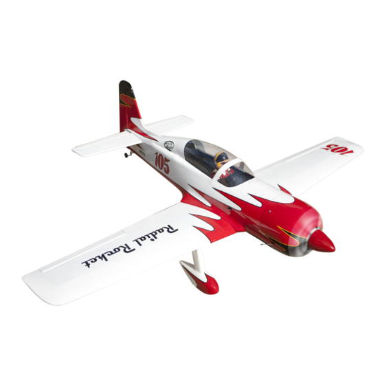
Specifications:
Wingspan---------------62.3 in (158.2 cm).
Wing area---------------570.4 sq.in (36.8sq.dm).
Weight-------------------7.1 - 7.3 lbs (3.2 - 3.3kg).
Length-------------------45.1in (114.5cm).
Engine-------------------10cc
----------------------------0.82 - 1.0 cu.in ------4-stroke
Radio--------------------5 channels with 7 servos.
LY
Electric conversion: Optional.
MS: 229
1
Advertisement
Table of Contents

Subscribe to Our Youtube Channel
Related Manuals for Seagull Models Radial Rocket JD 10cc


Summary of Contents for Seagull Models Radial Rocket JD 10cc
- Page 1 WWW.SEAGULLMODELS.COM A S S E M B L Y M A N U A L “ Graphics and specifications may change without notice “ . MS: 229 Specifications: Wingspan---------------62.3 in (158.2 cm). Wing area---------------570.4 sq.in (36.8sq.dm). Weight-------------------7.1 - 7.3 lbs (3.2 - 3.3kg). Length-------------------45.1in (114.5cm).
-
Page 2: Kit Contents
Instruction Manual. INTRODUCTION. Thank you for choosing the RADIAL ROCKET TD 10CC ARTF by SEAGULL MODELS COMPANY LTD,. The RADIAL ROCKET TD 10CC was designed with the intermedi- ate/advanced sport flyer in mind. It is a semi scale airplane which is easy to fly and quick to assemble. -
Page 3: Additional Items Required
WWW.SEAGULLMODELS.COM HINGING THE FLAP. KIT CONTENTS. SEA229 RADIAL ROCKET TD 10CC Note : The control surfaces, including the ai- SEA22901 Fuselage lerons, elevators, and rudder, are prehinged SEA22902 Wing set with hinges installed, but the hinges are not glued in place. It is imperative that you prop- SEA22903 Tail set erly adhere the hinges in place per the steps SEA22904 Canopy... -
Page 4: Hinging The Aileron
RADIAL ROCKET 10cc Instruction Manual. 4) Deflect the aileron and completely satu- 8) After both ailerons are securely hinged, rate each hinge with thin C/A glue. The ailer- firmly grasp the wing panel and aileron to ons front surface should lightly contact the make sure the hinges are securely glued and wing during this procedure. -
Page 5: Hinging The Elevators
WWW.SEAGULLMODELS.COM 5) Turn the wing panel over and deflect the aileron in the opposite direction from the opposite side. Apply thin C/A glue to each hinge, making sure that the C/A penetrates into both the aileron and wing panel. 6) Using C/A remover/debonder and a pa- per towel, remove any excess C/A glue that Hinge. -
Page 6: Hinging The Rudder
RADIAL ROCKET 10cc Instruction Manual. 2) Carefully remove the elevator from one of the horizontal stabilizer panels. Note the position of the hinges. 3) Remove each hinge from the hori- zontal stabilizer panel and elevator and place a T-pin in the center of each hinge. - Page 7 WWW.SEAGULLMODELS.COM INSTALL FLAP CONTROL HORN. Elevator fiberglass control horn. Install the flap control horn using the same method as same as the aileron con- trol horns. Epoxy. INSTALL RUDDER CONTROL HORN. Fiberglass control horn. Repeat steps to install the rudder control horn as same as steps done for ailerons.
- Page 8 RADIAL ROCKET 10cc Instruction Manual. INSTALLING THE SWITCH RECEIVER. INSTALLING THE FUSELAGE SERVOS. Because the size of servos differ, you Install the switch into the precut hole in may need to adjust the size of the precut the side, in the fuselage. opening in the mount.
-
Page 9: Installing The Stopper Assembly
WWW.SEAGULLMODELS.COM Vent tube. Fuel pick up tube. Switch. INSTALLING THE STOPPER Fuel fill tube. ASSEMBLY. 1) Using a modeling knife, carefully cut 3) Carefully bend the second nylon tube up off the rear portion of one of the 3 nylon at a 45º... -
Page 10: Engine Mount Installation
RADIAL ROCKET 10cc Instruction Manual. 7) Slide the fuel tank into the fuselage. Guide the lines from the tank through the hole in the firewall. 8) Use plywood template to hold in place the fuel tank with C/A glue to secure the fuel tank inside the fuselage. - Page 11 WWW.SEAGULLMODELS.COM 4) On the fire wall has the location for the MOUNTING THE ENGINE - 10CC. throttle pusshrod tube (pre-drill). 1) Position the engine with the drive 5) Slide the pushrod tube in the firewall washer (125mm) forward of the firewall and guide it through the fuel tank mount.
- Page 12 RADIAL ROCKET 10cc Instruction Manual. COWLING. Please see these below pictures. 8) Reinstall the servo horn by sliding the connector over the pushrod wire. Center the throttle stick and trim and install the servo horn perpendicular to the servo center line. 9) Move the throttle stick to the closed po- sition and move the carburetor to closed.
- Page 13 WWW.SEAGULLMODELS.COM 1) Slide the fiberglass cowl over the en- gine and line up the back edge of the cowl with the marks you made on the fuselage then trim and cut as shown. Because of the size of the cowl, it may be nec- 3x10mm essary to use a needle valve extension for the high speed needle valve.
- Page 14 RADIAL ROCKET 10cc Instruction Manual. 5) Slide the pushrod tube in the firewall and guide it through the fuel tank mount. Use medium C/A to glue the tube to the firewall and the fuel tank mount. 6) Connect the Z-bend in the 450mm throttle pushrod to the outer hole of the carburetor arm.
- Page 15 WWW.SEAGULLMODELS.COM Trim and cut. 3x10mm 2) While keeping the back edge of the cowl flush with the marks, align the front of the cowl with the crankshaft of the engine. The front of the cowl should be positioned so the crankshaft is in nearly the middle of the cowl opening.
- Page 16 RADIAL ROCKET 10cc Instruction Manual. ELECTRIC POWER CONVERSION. 1) Locate the items neccessary to install the electric power conversion included with your model. M4x20mm 4) Attach the motor to the front of the electric motor box using four 4mm blind nut, four M3x15mm hex head bolts to se- cure the motor.
- Page 17 WWW.SEAGULLMODELS.COM 4 mm Balsa stick. Epoxy 6) Attach the speed control to the side of the motor box using two-sided tape and tie wraps. Connect the appropriate leads from the speed control to the mo- tor. Make sure the leads will not interfere with the operation of the motor.
-
Page 18: Installing The Propeller
RADIAL ROCKET 10cc Instruction Manual. INSTALLING THE PROPELLER. Servos Small weight Thread Because the size of servos differ, you may need to adjust the size of the precut opening in the mount. The notch in the sides of the mount allow the servo lead to pass through. - Page 19 WWW.SEAGULLMODELS.COM 8) A string has been provided in the wing to pull the aileron lead through to the wing root. Remove the string from the wing at the servo location and use the tape to attach it to the servo extension lead.
-
Page 20: Installing The Aileron Servo
RADIAL ROCKET 10cc Instruction Manual. INSTALLING THE AILERON SERVO. Repeat the procedure for the aileron servo. INSTALLING THE FLAP SERVO. Repeat the procedure for the aileron servo. 9) Set the aileron hatch in place and use a AILERON PUSHROD HORN Phillips screw driver to install it with four INSTALLATION. -
Page 21: Installing Landing Gear
WWW.SEAGULLMODELS.COM Use a felt tip pen to mark the wire where INSTALLING THE FLAP PUSHROD. it crosses the hole. Use a pair of pliers to put a shrp 90-degree bend in the wire at Repeat the procedure for the aileron the mark. - Page 22 RADIAL ROCKET 10cc Instruction Manual. 3) Install Fiberglass Wheel Pants into Wings. Epoxy. Drill. Drill.
-
Page 23: Installing The Horizontal Stabilizer
WWW.SEAGULLMODELS.COM 4) Install Wheels. INSTALLING THE HORIZONTAL STABILIZER. 1) Using a ruler and a pen, locate the cen- terline of the horizontal stabilizer, at the trailing edge, and place a mark. Use a tri- angle and extend this mark, from back to front, across the top of the stabilizer. - Page 24 RADIAL ROCKET 10cc Instruction Manual. Draw center line 2) Using a modeling knife, carefully re- move the covering at mounting slot of horizontal stabilizer ( both side of fuse- lage). 5) Remove the stabilizer. Using the lines you just drew as a guide, carefully remove the covering from between them using a modeling knife.
-
Page 25: Installing Vertical Stabilizer
WWW.SEAGULLMODELS.COM 7) When you are sure that everything is 1) Using a modeling knife, remove the aligned correctly, mix up a generous covering from over the precut hinge slot cut amount of 30 Minute Epoxy. Apply a thin into the lower rear portion of the fuselage. layer to the top and bottom of the stabi- lizer mounting area and to the stabilizer mounting platform sides in the fuselage. - Page 26 RADIAL ROCKET 10cc Instruction Manual. ELEVATOR PUSHROD HORN Epoxy INSTALLATION. 1) Locate items necessaryto install rud- der pushrod. 2) Install the elevator control horn using the same method as with the aileron con- trol horns. 3) Position the elevator control horn on the both side of elevator.
-
Page 27: Tail Wheel Installation
WWW.SEAGULLMODELS.COM RUDDER PUSHROD HORN INSTALLATION. 1) Locate items necessaryto install rud- der pushrod. Elevator control horn. 2) Adjust the wheel collar shown to set the height of the tailwheel wire. Then check to see if the long steering leg of the Rudder control horn. -
Page 28: Apply The Decals
RADIAL ROCKET 10cc Instruction Manual. INSTALLATION PILOT AND CANOPY. Epoxy. 1) Locate items necessary to install pilot, seats. 170mm 4) Position the canopy onto the fuselage. Trace around the canopy and onto the fuselage using a felt-tipped pen. 2) A scale pilot is included with this ARF. The Seagull Pilot included fitting well to the cockpit. - Page 29 WWW.SEAGULLMODELS.COM Attach the aluminium tube into fuselage. INSTALLING BATTERY - RECEIVER. 1) Plug the five servo leads and the switch lead into the receiver. Plug the battery pack lead into the switch also. 2) Wrap the receiver and battery pack in the protective foam rubber to protect them from vibration.
- Page 30 RADIAL ROCKET 10cc Instruction Manual. BALANCING. 1) It is critical that your airplane be balanced correctly. Improper balance will cause your plane to lose control and crash. THE CENTER OF GRAV- ITY IS LOCATED 88MM BACK FROM THE LEADING EDGE OF THE WING AT THE WING ROOT.
-
Page 31: Control Throws
WWW.SEAGULLMODELS.COM With the wing attached to the fuselage, all parts of the model installed ( ready to fly), and empty fuel tanks, hold the mod- 88 mm el at the marked balance point with the stabilizer level. Lift the model. If the tail drops when you lift, the model is “tail heavy”... -
Page 32: Flight Preparation
RADIAL ROCKET 10cc Instruction Manual. FLIGHT PREPARATION. PREFLIGHT CHECK. Check the operation and direction 1) Completely charge your trans- of the elevator, rudder, ailerons and mitter and receiver batteries before throttle. your first day of flying. A) Plug in your radio system per the 2) Check every bolt and every glue manufacturer’s instructions and turn joint in the RADIAL ROCKET TD...
Need help?
Do you have a question about the Radial Rocket JD 10cc and is the answer not in the manual?
Questions and answers