
Related Manuals for Planet ICG-2510W-LTE Series


Summary of Contents for Planet ICG-2510W-LTE Series
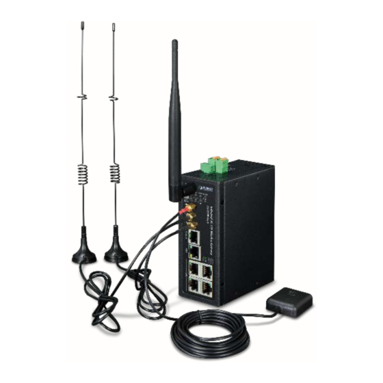
- Page 1 Industrial 4G LTE Cellular Wireless Gateway with 5-Port 10/100/100T ICG-2510W-LTE/ICG-2510WG-LTE Series...
- Page 2 PLANET has made every effort to ensure that this User's Manual is accurate; PLANET disclaims liability for any inaccuracies or omissions that may have occurred.
- Page 3 Do not dispose of WEEE as unsorted municipal waste and have to collect such WEEE separately. Revision PLANET ICG-2510W(G)-LTE Series User's Manual Model: ICG-2510W-LTE and ICG-2510WG-LTE Series Revision: 1.0 (October, 2019) Part No: EM-ICG-2510W(G)-LTE Series_v1.0...
-
Page 4: Table Of Contents
TABLE OF CONTENTS INTRODUCTION .......................... 7 1.1. Packet Contents ............................7 1.2. Product Description ..........................8 1.3. How to Use This Manual ........................13 1.4. Product Features ........................... 14 1.5. Product Specifications ........................... 16 INSTALLATION ........................... 19 2.1. Hardware Description ..........................19 2.1.1. - Page 5 4.3. Management and Configuration ......................33 4.3.1. Setting ................................ 33 4.3.1.1. Basic Setting ............................33 4.3.1.2. DDNS............................... 44 4.3.1.3. Clone MAC Address ..........................45 4.3.1.4. Advanced Routing ........................... 46 4.3.1.5. VLANS ..............................47 4.3.1.6. Networking ............................. 48 4.3.2. Wireless ..............................52 4.3.2.1.
- Page 6 4.3.10.6. Backup ..............................92 4.3.11. Status ............................... 93 APPENDIX A RJ45 PIN ASSIGNMENTS ................94 5.1. A.1 10/100Mbps, 10/100BASE-TX ......................94...
-
Page 7: Introduction
1. INTRODUCTION Thank you for purchasing PLANET Industrial 4G LTE Cellular Wireless Gateway. Please refer to the table list below for the models used in Europe and the U.S.: 4G LTE Model Name ICG-2510W-LTE-EU B1/B3/B5/B7/B8/B20 B38/B40/B41 █ ICG-2510WG-LTE-EU ICG-2510W-LTE-US B2/B4/B12 █... -
Page 8: Product Description
1.2. Product Description Making Network Connection Easy with 4G LTE Cellular Gateway PLANET ICG-2510W(G)-LTE series is a reliable, secure and high-bandwidth communications industrial-grade cellular gateway for demanding mobile applications, M2M (machine-to-machine) and IoT deployments. It features 4G LTE (Long Term Evolution), 2.4G/5G Wi-Fi, five Ethernet ports (4 LAN and 1 WAN), serial console port, DI and DO interfaces, and VPN technology bundled in a compact yet rugged metal case. - Page 9 Dual-band WLAN Solution PLANET ICG-2510W(G) series, adopting the IEEE 802.11b/g/n/ac standard, provides a high-speed transmission of power and data, meaning two remote nodes in the 5GHz frequency band can be bridged. The 2.4GHz wireless connection can also be used simultaneously.
- Page 10 Remote Manageable Solution for Ethernet to RS232/RS485 Application PLANET ICG-2510W(G)-LTE series’ serial RS232/RS485 communication interface can be converted over the Fast Ethernet networking. It can operate as a virtual server or client where IP-based serial equipment can be managed. The ICG-2510W(G)-LTE series helps save the network administrator’s valuable time in detecting and locating network...
- Page 12 Superior Management Functions For networking management features, the ICG-2510W(G)-LTE series provides such functions as DHCP server, DMZ and port forwarding, as well as full secure functions including Network Address Translation (NAT), WAN access policy, URL/Packet/MAC filtering. The ICG-2510W(G)-LTE series has 4G and WAN connection failover characteristics, which can automatically switch over to the redundant, stable WAN connection to keep users always online without missing any fascinating moments.
-
Page 13: How To Use This Manual
1.3. How to Use This Manual This User Manual is structured as follows: Section 2, INSTALLATION The section explains the functions of the Cellular Gateway and how to physically install the Cellular Gateway. Section 3, CELLULAR GATEWAY MANAGEMENT The section contains the information about the software function of the Cellular Gateway. Section 4, WEB CONFIGURATION The section explains how to manage the Cellular Gateway by Web interface. -
Page 14: Product Features
1.4. Product Features Benefits ■ Dual module SIMs for network load balancing and redundancy ■ Wi-Fi compliant IEEE 802.11b/g/n/ac dual-band for mobile client connectivity ■ 5-port Gigabit Ethernet, built-in redundant VRRP protocol ■ 2 DI, 1 DO and 1 serial console port (RS232 or RS485) for Modbus applications ■... - Page 15 ■ Supports IPSec (3DES, AES128, AES256, MD5, SHA1, SHA2-256, SHA2-512) ■ Supports TCP, UDP, TCP Server and Modbus TCP ■ Supports Dynamic DNS and PLANET DDNS ■ Provides Firewall and access policy functions ■ Supports WAN connection types: DHCP-4G, DHCP Client, Static IP, PPPoE Client, 3G Link1, 3G Link 2, DHCP-Backup 4G ■...
-
Page 16: Product Specifications
1.5. Product Specifications Product ICG-2510W-LTE ICG-2510WG-LTE Hardware Specifications 4 LAN 10/100/1000BASE-T RJ45 auto-MDI/MDI-X ports Copper Ports 1 WAN 10/100/1000BASE-T RJ45 auto-MDI/MDI-X port DB9 to RJ45 serial console port TCP/UDP PAD mode Modbus (ASCII, DTU, variable) Serial Interface ... - Page 17 LNK/ACT (Green) LTE SIM and Signal : SIM1 and SIM2 (Blue) LTE signal: High and low (Blue) Dimensions (W x D x H) 133 x 115.7 x 45 mm Weight 564g Power Requirements – DC 9~36V DC, 1.5A Power Consumption 8.4 watts/28.6 BTU Multi Band Supports ...
- Page 18 Supports QoS for bandwidth management Supports VLAN, 15 VLAN ID Other Supports Modbus TCP (only functions with console) Supports Port Forwarding Supports Dynamic DNS and PLANET DDNS Supports NTP client Management Basic Management Console, Telnet, HTTP, HTTPS, SNMP v1, v2c, CMS...
-
Page 19: Installation
2. INSTALLATION This section describes the hardware features and installation of the Industrial Cellular Gateway on the desktop or mounting. For easier management and control of the Industrial Cellular Gateway, familiarize yourself with its display indicators and ports. Front panel illustrations in this chapter display the unit LED indicators. Before connecting any network device to the Industrial Cellular Gateway, please read this chapter completely. -
Page 20: Led Indications
Reset Button On the front of the ICG-2510W(G)-LTE series, the reset button is designed to reboot the Industrial Cellular Gateway without turning off and on the power. The following is the summary table of the reset button functions: Figure 2-3 Rest Button of ICG-2510W(G)-LTE Series Reset Button Pressed and Released Function Reset the Industrial Cellular Gateway to Factory Default... -
Page 21: Cellular Gateway Upper Panel
10/100/1000BASE-T LAN Port Interfaces (Port-1 to Port-4) Color Function Lights Indicates that the link is successfully established. Ethernet Green Blinking Indicates that the port is actively sending or receiving data. 10/100/1000BASE-T WAN Port Interface Color Function Lights Indicates that the link is successfully established. Ethernet Green Blinking... -
Page 22: Wiring The Digital Input/Output And Relay
2.1.5. Wiring the Digital Input/Output and Relay The two 3-contact terminal block connectors on the top panel of ICG-2510W(G)-LTE Series is used for Digital Input, Digital Output and Relay. Digita Digital l Input Output Relay Figure 2-6 Wiring the DI/DO Inputs and Relay Input ON 5 to 30 VDC Input OFF... -
Page 23: Dual Sim Cards Installation
Blue Green Transmit Data Input White/ Data Terminal Ready Input Brown Brown Request To Send Input 2.1.7. Dual SIM Cards Installation Before inserting or removing the SIM card, ensure that the power has been turned off and the power connector has been removed from Cellular Gateway. -
Page 24: Installing Microsd Card
2.1.8. Installing MicroSD Card The ICG-2510W(G)-LTE series provides a MicroSD card slot . Refer to the SIM card installation method for inserting the MircoSD card. -
Page 25: Mounting Installation
2.2. Mounting Installation This section describes how to install your Industrial Cellular Gateway and make connections to the Industrial Cellular Gateway. Please read the following sections and perform the procedures in the order being presented. To install your Industrial Cellular Gateway on a desktop or shelf, simply complete the following steps. 2.2.1. - Page 26 Step 2: Place the bottom of DIN-rail bracket lightly into the track. Step 3: Check whether the DIN-rail bracket is tightly on the track. Step 4: Please refer to the following procedures to remove the Industrial Cellular Gateway from the track. Step 5: Lightly pull out the bottom of DIN-rail bracket to remove it from the track.
-
Page 27: Cellular Gateway Management
3. CELLULAR GATEWAY MANAGEMENT This chapter explains the methods that you can use to configure management access to the Industrial Cellular Gateway. It describes the types of management applications and the communication and management protocols that deliver data between your management device (workstation or personal computer) and the system. It also contains information about port connection options. -
Page 28: Management Access Overview
3.2. Management Access Overview The Industrial Cellular Gateway gives you the flexibility to access and manage it using any or all of the following methods: Web browser interface An external SNMP-based network management application The Web browser interfaces are embedded in the Industrial Cellular Gateway software and are available for immediate use. -
Page 29: Web Management
3.3. Web Management The Industrial Cellular Gateway offers management features that allow users to manage the Industrial Cellular Gateway from anywhere on the network through a standard browser such as Microsoft Internet Explorer. After you set up your IP address for the cellular gateway, you can access the Industrial Cellular Gateway's Web interface applications directly in your Web browser by entering the IP address of the Industrial Cellular Gateway. -
Page 30: Snmp-Based Network Management
3.4. SNMP-based Network Management You can use an external SNMP-based application to configure and manage the Industrial Cellular Gateway, such as SNMPc Network Manager, HP Openview Network Node Management (NNM) or What’s Up Gold. This management method requires the SNMP agent on the cellular gateway and the SNMP Network Management Station to use the same community string. -
Page 31: Web Configuration
4. WEB CONFIGURATION This chapter describes how to configure and manage the cellular gateway 4.1. Configuration Connection Before configuration, you should connect the cellular gateway and your configuration PC with the supplied network cable. Plug the cable’s one end into the Local Network port of the cellular gateway, and another end into your configure PC’s Ethernet port. - Page 32 The information main page is shown below. Users need to input user name and password if it is their first time to log in. Input correct user name and password to visit relevant menu page. Default user name and password are admin.
-
Page 33: Management And Configuration
4.3. Management and Configuration The Industrial Cellular Gateway offers management features that allow users to manage the Industrial Cellular Gateway from anywhere on the network through a standard browser such as Microsoft Internet Explorer. After you set up your IP address for the cellular gateway, you can access the Industrial Cellular Gateway's Web interface applications directly in your Web browser by entering the IP address of the Industrial Cellular Gateway. - Page 34 Object – Static IP Description WAN IP Address Users set IP address by their own or ISP assigns Subnet Mask Users set subnet mask by their own or ISP assigns Gateway Users set gateway by their own or ISP assigns Static DNS1/DNS2/ Users set static DNS by their own or ISP assigns DNS3...
- Page 35 Object – Description dhcp-4G User Name Login user’s ISP (Internet Service Provider) Password Login user’s ISP Access point name of user’s ISP PIN code of user’s SIM card...
- Page 36 PPPoE Object – PPPoE Description User Name Login the Internet Password Login the Internet...
- Page 37 3G Link1 Object – 3G Description Link1 User Name Login user’s ISP (Internet Service Provider) Password Login user’s ISP Dial String Dial number of user’s ISP Access point name of user’s ISP PIN code of user’s SIM card...
- Page 38 3G Link2 Object – 3G Description Link2 User Name Login user’s ISP (Internet Service Provider) Password Login user’s ISP Dial String Dial number of user’s ISP Access point name of user’s ISP PIN code of user’s SIM card dhcp-bkup4G IP address of WAN port gets automatic via DHCP-4G.
- Page 39 Object – Description dhcp-bkup4G User Name Login user’s ISP (Internet Service Provider) Password Login user’s ISP Access point name of user’s ISP PIN code of user’s SIM card Connection Type The connection type provides 12 options for required mode. This option allows user to select connection type which he prefers, such as auto, force 3G or force 4G.
- Page 40 Keep Online This function is used to detect whether the Internet connection is active, if users set it and when the Router detects the connection is inactive, it will redial to users' ISP immediately to make the connection active. If the network is busy or the user is in private network, we recommend that Router mode will be better.
- Page 41 Force reconnect This option schedules the PPPoE or 3G reconnection by killing the pppd daemon and restarts it. After enabling the function, you are able to set the time to reconnect. STP (Spanning Tree Protocol) can be applied to loop network. Through certain algorithm achieves path redundancy, and loop network cuts to tree-based network without loop, thus avoiding the hyperplasia and infinite circulation of a message in the loop network.
- Page 42 LAN Network Setup Object – Router Description Local IP Address IP address of the gateway. The default IP address is 192.168.1.1 Subnet Mask The subnet mask of the gateway Set internal gateway of the cellular gateway. By default, internal Gateway gateway is the address of the gateway DNS server is auto assigned by network operator server.
- Page 43 Object – DHCP Description DHCP Type DHCP Server and DHCP Forwarder Keep the default Enable to enable the gateway's DHCP server option. If DHCP Server users already have a DHCP server on their network or users do not want a DHCP server, then select Disable. Enter a numerical value for the DHCP server to start with when issuing Start IP Address IP addresses.
-
Page 44: Ddns
Users' domain name in the field of local search increases the expansion of the host option to adopt DNSMasq that can assign IP addresses and DNSMasq DNS for the subnet. If select DNSMasq, dhcpd service is used for the subnet IP address and DNS. Time Settings Select time zone of your location. -
Page 45: Clone Mac Address
Object – DDNS Description Supports PLANETDDNS, PLANET EasyDDNS, DynDNS, freedns, DDNS Service Zoneedit, NO-IP, 3322, easyDNS, TZO, DynSIP and Custom based on the user User Name Users register in DDNS server, up to 64 characteristic Users register in DDNS server, not limited for input characteristic for Host Name IP address of NTP server, up to 32 characters. -
Page 46: Advanced Routing
4.3.1.4. Advanced Routing Operating Mode: Gateway, BGP, RIP2 Router, OSPF Router and Router If the Router is hosting users' Internet connection, select Gateway mode. If another Router exists on their network, select Router mode. Dynamic Routing Dynamic Routing enables the Router to automatically adjust to physical changes in the network's layout and exchange routing tables with other Routers. -
Page 47: Vlans
Static Routing Object – Static Description Routing Select set 1-50 number Route Name Defined routing name by users, up to 25 characters Metric 0-9999 Destination LAN The Destination IP Address is the address of the network or host to which users want to assign a static route The Subnet Mask determines which portion of an IP address is the Subnet Mask network portion, and which portion is the host portion... -
Page 48: Networking
meanwhile LAN port and WAN port disable is to divide into one VLAN port. 4.3.1.6. Networking Object – Description Networking... - Page 49 Creates a new empty network bridge for later use. STP means Bridging-Create Spanning Tree Protocol and with PRIO users are able to set the bridge Bridge priority order. The lowest number has the highest priority. Allows users to assign any valid interface to a network bridge. Consider Bridging-Assign setting the Wireless Interface options to Bridged if they want to assign to Bridge...
- Page 50 Prio means priority level: work if multiple ports are within the same bridge. The smaller the number gets, the higher the level is. Click 'Add' to take effect. The corresponding interfaces of WAN ports should not be bound; this bridge function is basically used for LAN port, and should not be bound with WAN port If binding is successful, bridge binding list in the list of current bridging table is shown below: To make br1 bridge have the same function with DHCP assigned address, users need to set multiple DHCP functions.
- Page 51 Object – Port Description Setup-Unbridged Maximum transfer unit Multicast Enable or disable multicast forwarding forwarding Masquerade/NAT Enable or disable Masquerade/NAT IP Address Set ra0's IP address, and do not conflict with other ports or bridge Subnet Mask Set the port's subnet mask Multiple DHCPDs Using multiple DHCP service -- Click 'Add' in multiple DHCP servers to appear relevant configuration.
-
Page 52: Wireless
4.3.2. Wireless 4.3.2.1. Basic Settings Wireless Physical Interface Object – Description Wireless Basic Settings Wireless Enable is for radio on and Disable is for radio off Network Wireless Mode AP, Client, Repeater, Repeater Bridge Wireless Disabled, Mixed, BG-Mixed, B-Only, G-Only, NG-Mixed, N-Only Network Mode Wireless Network Name... -
Page 53: Wireless Security
Broadcast Network IP address needs to be manually configured when unbridged is selected Configuration Virtual Interfaces Click Add to add a virtual interface. Click on the remove to remove the virtual interface. Object – Virtual Description Server This setting isolates wireless client so access to and from other wireless AP Isolation clients are stopped. - Page 54 Object – Description Wireless Security-WEP Authentication Open or shared key Type Default Transmit Select the key from Key 1 to Key 4. There are two levels of WEP encryption, 64-bit (40-bit) and 128-bit. To utilize WEP, select the desired encryption bit, and enter a passphrase or WEP key in hexadecimal format.
- Page 55 WPA Personal/WPA2 Personal/WPA2 Personal Mixed Object – Description Wireless Security-WPA Personal/WPA2 Personal/WPA2 Personal Mixed WPA Algorithms TKIP, AES and TKIP + AES WPA Shared Key Between 8 and 63 ASCII characters or hexadecimal digits Key Renewal Interval (in 1-99999 seconds) WPA Enterprise/WPA2 Enterprise/WPA2 Enterprise Mixed Object –...
-
Page 56: Services
Radius Auth The RADIUS port and the default is 1812 Server Port Radius Auth The shared secret from the RADIUS server Shared Secret Key Renewal Interval (in 1-99999 seconds) 4.3.3. Services 4.3.3.1. Services DHCP Server DHCPd assigns IP addresses to user local devices. While the main configuration is on the setup page users can program some nifty special functions here. - Page 57 Object – Description DNSMasq Enables DHCP clients on the LAN to resolve static and dynamic DHCP Local DNS host names. When enabled, it can prevent an external attacker to access the No DNS Rebind gateway's internal Web interface. It is a secure measure. Some extra options users can set by entering them in Additional DNS Options.
- Page 58 Options. For example: Static allocation: dhcp-host=AB:CD:EF:11:22:33,192.168.0.10,myhost,myhost.domain,12h Max lease number: dhcp-lease-max=2 DHCP server IP range: dhcp-range=192.168.0.110,192.168.0.111,12h RO Community SNMP RO community name, the default is public, Only to read SNMP RW community name, the default is private, Read-write RW Community permissions SSHD Enabling SSHd allows users to access the Linux OS of their Router with an SSH client.
- Page 59 Object – System Description The Syslog Out Mode supports four log modes. Syslog Out Mode Net: the log information output to a syslog server Console: the log information output to console port If net mode is chosen, users should input a syslog server’s IP Address Remote Server and run a syslog server program on it Telnet...
-
Page 60: Vpn
4.3.4. VPN 4.3.4.1. PPTP PPTP Server Object – PPTP Server Description Broadcast Support Enable or disable broadcast support of PPTP server Force MPPE Encryption Enable of disable force MPPE encryption of PPTP data DNS1/DNS2/WINS1/WINS-2 Set DNS1/DNS2/WINS1/WINS2 Input IP address of the gateway as PPTP server, different from LAN Server IP address IP address is assigned to the client;... - Page 61 PPTP Client Object – PPTP Description Client Server IP or DNS PPTP server’s IP address or DNS name Name Remote Subnet The network of the remote PPTP server Remote Subnet Subnet mask of remote PPTP server Mask MPPE Enable or disable Microsoft Point-to-Point Encryption Encryption Maximum transmission unit Maximum receive unit...
-
Page 62: L2Tp
4.3.4.2. L2TP L2TP Server Object – L2TP Description Server Force MPPE Enable or disable force MPPE encryption of L2TP data Encryption Input IP address of the gateway as PPTP server, different from LAN Server IP address IP address is assigned to the client; the format is Client IP(s) xxx.xxx.xxx.xxx-xxx.xxx.xxx.xxx CHAP Secrets... - Page 63 L2TP Client Object – L2TP Description Client User Name User name to log in L2TP server Password Password to log in L2TP server Gateway (L2TP L2TP server’s IP Address or DNS Name Server) Remote Subnet The network of remote PPTP server Remote Subnet The subnet mask of remote PPTP server Mask...
-
Page 64: Openvpn
Authentication 4.3.4.3. OPENVPN OPENVPN Server... - Page 65 Object – Description OPENVPN Server WAN UP: Start after online Start Type System: Start when booting up Config via Server or Daemon Server Mode Router (TUN) and Bridge (TAP) modes Router (TUN) Network: Network address allowed by OPENVPN server Mode Netmask: Netmask allowed by OPENVPN server...
- Page 66 DHCP-Proxy mode: enable or disable DHCP-Proxy mode Pool start IP: Pool start IP of the client allowed by OPENVPN server Bridge (TAP) Pool end IP: Pool end IP of the client allowed by OPENVPN server Mode Gateway: The gateway of the client allowed by OPENVPN server Netmask: Netmask of the client allowed by OPENVPN server Port Listen port of OPENVPN server...
- Page 67 OPENVPN Client Object – Description OPENVPN Client Server IP/Name IP address or domain name of OPENVPN server Port listen port of OPENVPN client TUN: Router mode Tunnel Device TAP: Bridge mode Tunnel Protocol UDP and TCP protocol Encryption Blowfish CBC, AES-128 CBC, AES-192 CBC, AES-256 CBC, AES-512 Cipher Hash algorithm provides a method of quick access to data, including Hash Algorithm...
- Page 68 Object – Description OPENVPN Client TLS (Transport Layer Security) encryption standard supports multiple TLS Cipher options Use LZO Enable or disable use LZO compression for data transfer Compression Enable or disable NAT through function Bridge TAP to Enable or disable bridge TAP to br0 IP Address Set IP address of local OPENVPN client Subnet mask...
-
Page 69: Ipsec
TUN MTU Setting Set MTU value of the tunnel TLS Auth Key Authority key of Transport Layer Security Additional Additional configurations of OPENVPN server Config Policy based Input some defined routing policy Routing CA Cert CA certificate Public Client Client certificate Cert Private Client Client key... - Page 70 Reconnect: This action will remove current tunnel, and re-launch tunnel establish request Enable: When the connection is enable, it will launch tunnel establish request when the system reboot or reconnect, otherwise the connection will not do it To add a new IPSEC connection Add IPSEC connection or edit IPSEC connection Type: To choose IPSEC mode and relevant functions in this part, supports tunnel mode client, tunnel mode server and transfer mode currently...
- Page 71 Detection: This part contains configure information of connection detection Object – IPSEC Description Enable DPD Enable or disable this function, tick means enable Detection Time Interval Set time interval of connect detection (DPD) Timeout Set the timeout of connect detection Action Set the action of connect detection Advanced Settings: This part contains relevant setting of IKE, ESP, negotiation mode, etc.
-
Page 72: Gre
ESP Keylife Set ESP keylife, current unit is hour, the default is 0 IKE aggressive Negotiation mode adopt aggressive mode if tick; it is main mode allowed mode if non-tick Perfect Forward Tick to enable PFS, non-tick to disable PFS Security (PFS) Authentication: Choose use share encryption option or certificate authentication option. - Page 73 Object – GRE Description Number Switch on/off GRE tunnel app Status Switch on/off someone GRE tunnel app Name GRE tunnel name Through The GRE packet transmit interface Peer Wan IP addr The remote WAN address Peer Subnet The remote gateway local subnet, eg: 192.168.1.0/24 Peer Tunnel IP The remote tunnel ip address Local Tunnel IP...
-
Page 74: Security
4.3.5. Security 4.3.5.1. Firewall You can enable or disable the firewall, filter specific Internet data types, and prevent anonymous Internet requests, ultimately enhancing network security. Firewall enhances network security and use SPI to check the packets in the network. To use firewall protection, choose enable otherwise disable. - Page 75 Object – Security Description Block By selecting “Block Anonymous WAN Requests (ping)” box to enable Anonymous this feature, you can prevent your network from the Ping or detection of WAN Requests other Internet users. The default state of this feature is enabled. When (ping) disable is selected, it allows anonymous Internet requests.
- Page 76 automatically dropped. Log Management The gateway can keep logs of all incoming or outgoing traffic for your Internet connection. Object – Log Description Management To keep activity logs, select Enable. To stop logging, select Disable. When selecting enable, the following page will appear.
-
Page 77: Access Restrictions
Set this to the required log level. Set Log Level higher to log more Log Level actions. When selecting Enable, the corresponding connection will be recorded Options in the journal; disable is not recorded. To see a temporary log of the Router's most recent incoming traffic, click Incoming Log the Incoming Log button. - Page 78 Object – WAN Description Access You may define up to 10 access policies. Click Delete to delete a policy Access Policy or Summary to see a summary of the policy. Status Enable or disable a policy. Policy Name You may assign a name to your policy. The part is used to edit client list;...
- Page 79 Address Website You can block access to certain website by the keywords contained in Blocking by their webpage Keyword The steps of setting up Internet access policy 1. Select the policy number (1-10) in the drop-down menu. 2. For this policy to be enabled, click the radio button next to "Enable" 3.
-
Page 80: Url Filter
setting, Deny. If you want the listed PCs to have Internet filtered during the designated days and time, then click the radio button next to Filter. 8. Set the days when access will be filtered. Select Everyday or the appropriate days of the week. 9. -
Page 81: Packet Filter
rules Accept only the data packets that Receive only custom rules of network address; discard all other URL conform to the addresses. following rules MAC Filter Object –MAC Description Filter Discard packets conform to the Only discard the matching MAC address in the list. following rules Accept only the data packets... -
Page 82: Nat
Object –Packet Description Filter Enable Packet Enable or disable “packet filter” function Filter Two policies are provided. One is Discard packets conform to the Policy following rules and the other is Accept only the data packets conform to the following rules. Add Filter Rule Input: packet from WAN to LAN Direction... -
Page 83: Port Forwarding
4.3.7.1. Port Forwarding Port Forwarding allows you to set up public services on your network, such as web servers, ftp servers, e-mail servers, or other specialized Internet applications. Specialized Internet applications are any applications that use Internet access to perform functions such as videoconferencing or online gaming. When users send this type of request to your network via the Internet, the Router will forward those requests to the appropriate PC. -
Page 84: Dmz
Object –Port Description Range Forward Application Enter the name of the application in the field provided. Enter the number of the first port of the range you want to be seen by Start users on the Internet and forwarded to your PC. Enter the number of the last port of the range you want to be seen by users on the Internet and forwarded to your PC. -
Page 85: Qos Setting
4.3.8. QoS Setting 4.3.8.1. Basic Bandwidth management prioritizes the traffic on your Router. Interactive traffic (telephony, browsing, telnet, etc.) gets priority and bulk traffic (file transfer, P2P) gets low priority. The main goal is to allow both types to work side-by-side leaving out unimportant traffic. -
Page 86: Applications
4.3.9. Applications 4.3.9.1. Serial Applications There is a console port on Router. Normally, this port is used to debug the Router. This port can also be used as a serial port. The Router has embedded a serial to TCP program. The data sent to the serial port is encapsulated by TCP/IP protocol stack and then is sent to the destination server. -
Page 87: Admin
Object –Serial Description Applications Baud rate indicates the number of bytes per second transported by Baudrate device, commonly used baud rate is115200, 57600, 38400, and 19200. The data bits can be 4, 5, 6, 7, 8, constitute a character. The ASCII code Databit is usually used. -
Page 88: Management
4.3.10.1. Management The Management screen allows you to change the Router's settings. On this page you will find most of the configurable items of the Router code. The new password must not exceed 32 characters in length and must not include any spaces. Enter the new password twice to confirm it. - Page 89 Info Site Enable or disable the password protection feature of the system Password information page. Protection Remote Access This feature allows you to manage the Router from a remote location via the Internet. To disable this feature, keep the default setting, Disable. To enable this feature, select Enable, and use the specified port (default is 8080) on your PC to remotely manage the Router.
-
Page 90: Keep Alive
Remote Management Firmware Upgrade Choose Enable to have a firmware upgrade. 4.3.10.2. Keep Alive User is able to reboot the device automatically by interval or specific time. -
Page 91: Commands
4.3.10.3. Commands The function allows you to run command line directly via the Web interface. Object – Description Commands You can run command lines via the web interface. Fill the text area with Run Commands your command and click Run Commands to submit. You can save some command lines to be executed at startup's Router. -
Page 92: Firmware Upgrade
Any settings you have saved will be lost when the default settings are restored. The default IP address is 192.168.1.1 and the default password is admin. 4.3.10.5. Firmware Upgrade 4.3.10.6. Backup Object –Backup Description You may back up your current configuration in case you need to reset Backup Settings the Router back to its factory default settings. -
Page 93: Status
back up your current configuration. Click the “Browse...” button to browse for a configuration file that is Restore Settings currently saved on your PC. Click the Restore button to overwrite all current configurations with the ones in the configuration file. 4.3.11. -
Page 94: Appendix A Rj45 Pin Assignments
5. APPENDIX A RJ45 Pin Assignments 5.1. A.1 10/100/1000Mbps, 10/100/1000BASE-T When connecting your 10/100/1000Mbps Cellular Gateway to another device, a bridge or a hub, a straight-through or crossover cable is necessary. Each port of the Cellular Gateway supports auto-MDI/MDI-X detection. That means you can directly connect the Cellular Gateway to any Ethernet devices without making a crossover cable. - Page 95 Straight-through Cable SIDE 1 SIDE 2 SIDE 1 1 = White / 1 = White / Orange Orange 2 = Orange 2 = Orange 3 = White / 3 = White / Green Green 4 = Blue 4 = Blue 5 = White / 5 = White / Blue...
Need help?
Do you have a question about the ICG-2510W-LTE Series and is the answer not in the manual?
Questions and answers