
Related Manuals for Planet IVR-100 Series


Summary of Contents for Planet IVR-100 Series
- Page 1 Industrial VPN Security Gateway IVR-100_IVR-300 Series Industrial 5-Port 10/100/1000T VPN Security Gateway IVR-100 & IVR-300 Series - 1 -...
- Page 2 PLANET has made every effort to ensure that this User’s Manual is accurate; PLANET disclaims liability for any inaccuracies or omissions that may have occurred. Information in this User’s Manual is subject to change without notice and does not represent a commitment on the part of PLANET.
- Page 3 WEEE as unsorted municipal waste and have to collect such WEEE separately. Trademarks The PLANET logo is a trademark of PLANET Technology. This documentation may refer to numerous hardware and software products by their trade names. In most, if not all cases, these designations are claimed as trademarks or registered trademarks by their respective companies.
-
Page 4: Table Of Contents
Setting TCP/IP on your PC ....................39 3.2.1 Windows 7/8 ..................... 39 3.2.2 Windows 10 ...................... 43 Planet Smart Discovery Utility ..................... 46 Chapter 4. Web-based Management ....................48 Introduction .......................... 48 Logging in to the VPN Gateway ..................48 Main Web Page ........................ - Page 5 Industrial VPN Security Gateway IVR-100_IVR-300 Series 4.4.7 SFP Module Information ................... 68 4.4.8 High Availability ....................69 4.4.9 RADIUS......................70 4.4.10 Captive Portal ....................72 4.4.11 SNMP ........................ 73 4.4.12 NMS ........................74 4.4.13 Fault Alarm ......................76 4.4.14 Digital Input / Output ..................77 4.4.15 Modbus ......................
- Page 6 Industrial VPN Security Gateway IVR-100_IVR-300 Series 4.7.6 SSL VPN ......................115 4.7.7 Certificates ...................... 116 4.7.8 VPN Connection ..................... 116 4.7.9 SD WAN ......................116 AP Control ......................... 117 4.8.1 Preference ...................... 119 4.8.2 AP Search ....................... 119 4.8.3 AP Management ..................... 120 4.8.4 AP Group Management ..................
-
Page 7: Chapter 1. Product Introduction
Industrial VPN Security Gateway IVR-100_IVR-300 Series Chapter 1. Product Introduction Thank you for purchasing PLANET Industrial Security Gateway, IVR-100 and IVR-300 series. The descriptions of these models are as follows IVR-100 Industrial 5-Port 10/100/1000T VPN Security Gateway IVR-300 Industrial 5-Port 10/100/1000T VPN Security Gateway with Redundant Power IVR-300W Industrial 5-Port 10/100/1000T + 802.11ax Wi-Fi VPN Security Gateway... -
Page 8: Overview
1.2 Overview Powerful Industrial VPN Security Solution PLANET has launched the IVR-100 and IVR-300 Series Security Gateway for demanding applications. It features five Ethernet ports (4 LANs and 1 WAN), IEEE 11ax Wi-Fi capability (for IVR-300W), one Fiber port (for IVR-300FP), RS485 serial port (for IVR-300 series), and DI and DO interfaces. Incorporating SD-WAN function, it can greatly increase WAN optimization for multiple WAN links to be managed. - Page 9 Industrial VPN Security Gateway IVR-100_IVR-300 Series Built-in Unique PoE Functions for Powered Devices Management (For IVR-300FP) The IVR-300FP is capable of having a maximum of up to 120 watts of power output and can deliver up to 36W for each port. It also features the following special PoE management functions. PoE Usage Monitoring (For IVR-300FP) With PoE usage monitoring, it can show the PoE loading of each port, total PoE power usage and system...
- Page 10 Industrial VPN Security Gateway IVR-100_IVR-300 Series Scheduled Power Recycling (For IVR-300FP) The IVR-300FP allows each of the connected PoE IP cameras or PoE wireless access points to reboot at a specific time each week. Therefore, it will reduce the chance of IP camera or AP crash resulting from buffer overflow.
- Page 11 Centralized Remote Control of Managed APs The IVR-100 and IVR-300 Series provides centralized management of PLANET Smart AP series via a user-friendly Web GUI. It's easy to configure AP for the wireless SSID, radio band and security settings. With a four-step configuration process, wireless profiles for different purposes can be simultaneously delivered to multiple APs or AP groups to minimize deployment time, effort and cost.
- Page 12 Industrial VPN Security Gateway IVR-100_IVR-300 Series For example, to configure multiple smart APs of the same model, the IVR-100 and IVR-300 Series allows clustering them to a managed group for unified management. According to requirements, wireless APs can be flexibly expanded or removed from a wireless AP group at any time. The AP cluster benefits bulk provision and bulk firmware upgrade through single entry point instead of having to configure settings in each of them separately.
- Page 13 DC power supply inputs for high availability applications. Ideal VPN Security Gateway PLANET IVR-100 and IVR-300 Series can work as a VPN security gateway in an industrial application for a company that has a factory and many different divisions. With IPSec/GRE/PPTP/L2TP/SSL VPN solutions, the IVR-100 and IVR-300 Series installed at the headquarters provides branches, vendors, and mobile workers with secure data communication no matter how long the distance would be.
- Page 14 Industrial VPN Security Gateway IVR-100_IVR-300 Series The IVR-100 and IVR-300 Series connects dual WANs with up to two different ISPs. It creates a stable and qualified VPN connection for many important applications such as VoIP, video conferencing and data transmission. - 14 -...
-
Page 15: Features
Industrial VPN Security Gateway IVR-100_IVR-300 Series 1.3 Features Hardware 4 x 10/100/1000BASE-T RJ45 LAN ports (for IVR-100 and IVR-300/IVR-300W) 4 x 10/100/1000BASE-T RJ45 LAN ports with 4-port IEEE 802.3at PoE+ injector function (for IVR-300FR) 1 1000BASE-X SFP slot for WAN/LAN interface(for IVR-300FR) ... - Page 16 Industrial VPN Security Gateway IVR-100_IVR-300 Series Industrial Case and Installation IP30 metal case Solid DIN-rail, wall-mount or side wall-mount design Supports 6KV DC Ethernet ESD protection Fault alarm for power input failure DC redundant power with reverse polarity protection -40 to 75 degrees C operating temperature ...
- Page 17 Dashboard for real-time system overview Support for HTTP or HTTPS Auto reboot PLANET NMS System and Smart Discovery Utility for deployment management PLANET CloudViewer app for real-time monitoring Configuration backup and restoration via remote/USB port ...
-
Page 18: Product Specifications
Industrial VPN Security Gateway IVR-100_IVR-300 Series 1.4 Product Specifications IVR-100 IVR-300 IVR-300W IVR-300FP Product Hardware Specifications 5 10/100/1000BASE-T RJ45 Ethernet ports including 3 LAN ports (Ports 1 to 3) Copper Ports 1 LAN/WAN port (Port 4) 1 WAN port (Port 5) 1 1000BASE-X SFP slot including Fiber Port... - Page 19 Industrial VPN Security Gateway IVR-100_IVR-300 Series System: System: System: System: P1 (Green) P1 (Green) P1 (Green) P1 (Green) P2 (Green) P2 (Green) P2 (Green) P2 (Green) Fault (Red) Alarm (Red) Alarm (Red) Alarm (Red) I/O (Red) I/O (Red) I/O (Red) Per 10/100/1000 Per 10/100/1000 Per 10/100/1000...
- Page 20 IGMP Proxy Multicast Max. 900Mbps NAT Throughput Outbound Load Supported algorithms: Weight Balancing IPv4, IPv6, TCP/IP, UDP, ARP, HTTP, HTTPS, NTP, DNS, PLANET DDNS, Protocol PLANET Easy DDNS, DHCP, PPPoE, SNMPv1/v2c/v3 HA (High Availability) Captive Portal Key Features RADIUS Server/Client...
- Page 21 Industrial VPN Security Gateway IVR-100_IVR-300 Series Diagnostics Configuration backup and restoration via remote/USB port Firmware upgrade via remote/USB port Standards Conformance Regulatory CE, FCC Compliance Environment Temperature: -40 ~ 75 degrees C Operating Relative humidity: 5 ~ 90% (non-condensing) Temperature: -40 ~ 85 degrees C Storage Relative humidity: 5 ~ 90% (non-condensing) Power of Ethernet Specification for IVR-300FP...
- Page 22 Industrial VPN Security Gateway IVR-100_IVR-300 Series America FCC: Non-DFS: 36, 40, 44, 48, 149,153,157,161,165 DFS: 52, 56, 60, 64, 100, 104, 108, 112, 116, 132, 136, 140 Europe ETSI: 5GHz Non-DFS: 36, 40, 44, 48 DFS: 52, 56, 60, 64, 100, 104, 108, 112, 116, 120, 124, 128, 132, 136, 140 5GHz channel list may vary in different countries according to their regulations.
-
Page 23: Chapter 2. Hardware Introduction
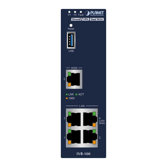
Industrial VPN Security Gateway IVR-100_IVR-300 Series Chapter 2. Hardware Introduction 2.1 Physical Descriptions 2.1.1 Front View IVR-100 Front Panel Color Function Green Lights to indicate DC power input 1 has power. Green Lights to indicate DC power input 2 has power. Fault Lights to indicate the either power or port fail Indicates the link through that port is successfully established at 1000Mbps... - Page 24 Industrial VPN Security Gateway IVR-100_IVR-300 Series Ports USB 3.0 port for system configuration backup and restoration. USB Port Power on the device and press the reset button for less than 5 seconds to reboot it or Reset Button over 5 seconds to restore it to factory default settings. It is a LAN port for connecting to a switch.
- Page 25 Industrial VPN Security Gateway IVR-100_IVR-300 Series LED Definition: System: Color Function Green Lights to indicate DC power input 1 has power. Green Lights to indicate DC power input 2 has power. Alarm Lights to indicate the either power or port fail Indicate Condition of Digital Input or Digital Output has triggered.
- Page 26 Industrial VPN Security Gateway IVR-100_IVR-300 Series 1000BASE-X SFP WAN/LAN Port (Port 6) Color Function Lights Indicates the port is operating at 1000Mbps. 1000 Green LNK/ACT Blinks Indicates that the switch is actively sending or receiving data over that port. Ports USB 3.0 port for system configuration backup and restoration.
-
Page 27: Top View
Industrial VPN Security Gateway IVR-100_IVR-300 Series 2.1.2 Top View The upper panel of the Industrial Gateway consists of one terminal block connector within two DC power inputs. IVR-100 Top View IVR-300/IVR-300W Top View IVR-300FP Top View - 27 -... -
Page 28: Wiring The Power Inputs
Industrial VPN Security Gateway IVR-100_IVR-300 Series 2.1.3 Wiring the Power Inputs The 6-contact terminal block connector on the top panel of Industrial Gateway is used for two DC redundant power inputs. Please follow the steps below to insert the power wire. When performing any of the procedures like inserting the wires or tightening the wire-clamp screws, make sure the power is OFF to prevent from getting an electric shock. -
Page 29: Wiring The Fault Alarm Contact
Industrial VPN Security Gateway IVR-100_IVR-300 Series The wire gauge for the terminal block should be in the range from 12 to 24 AWG. PWR1 and PWR2 must provide the same DC voltage while operating with dual power input. 2.1.4 Wiring the Fault Alarm Contact The fault alarm contacts are in the middle of the terminal block connector as the picture shows below. -
Page 30: Dimensions
Industrial VPN Security Gateway IVR-100_IVR-300 Series 2.1.5 Dimensions IVR-100 Dimensions - 30 -... - Page 31 Industrial VPN Security Gateway IVR-100_IVR-300 Series IVR-300 Dimensions - 31 -...
- Page 32 Industrial VPN Security Gateway IVR-100_IVR-300 Series IVR-300W Dimensions - 32 -...
- Page 33 Industrial VPN Security Gateway IVR-100_IVR-300 Series IVR-300W Dimensions - 33 -...
-
Page 34: Hardware Installation
Industrial VPN Security Gateway IVR-100_IVR-300 Series 2.2 Hardware Installation This section describes how to install the Industrial Gateway. There are three methods to install the Industrial Gateway -- DIN-rail mounting, wall mounting and side wall mounting. Basic knowledge of networking is assumed. - Page 35 Industrial VPN Security Gateway IVR-100_IVR-300 Series Step 3: Connect your device to hub / switch. A. Connect one end of a standard network cable to the LAN port (port 1) of the device. B. Connect the other end of the cable to the hub / switch. The UTP Category 5, 5e or 6 network cabling with RJ45 tips is recommended.
-
Page 36: Wall Mount Plate Mounting
Industrial VPN Security Gateway IVR-100_IVR-300 Series 2.2.2 Wall Mount Plate Mounting To install the Industrial Gateway on the wall, please follow the instructions below. Step 1: Remove the DIN-rail from the Industrial Gateway. Use the screwdriver to loosen the screws to remove the DIN-rail. -
Page 37: Side Wall Mount Plate Mounting
Industrial VPN Security Gateway IVR-100_IVR-300 Series 2.2.3 Side Wall Mount Plate Mounting To install the Industrial Gateway on the wall, please follow the instructions below. Step 1: Remove the DIN-rail from the Industrial Gateway. Use the screwdriver to loosen the screws to remove the DIN-rail. -
Page 38: Wi-Fi Antenna Installation
Industrial VPN Security Gateway IVR-100_IVR-300 Series 2.2.4 Wi-Fi Antenna Installation (For IVR-300W only) Step 1: Fasten the two dual-band antennas to the antenna connectors on the front panel of the IVR-300W. Step 2: You can bend the antennas to fit your actual needs. Figure 2-2: IVR-300W Front Panel - 38 -... -
Page 39: Chapter 3. Preparation
Industrial VPN Security Gateway IVR-100_IVR-300 Series Chapter 3. Preparation Before getting into the device’s web UI, user has to check the network setting and configure PC’s IP address. 3.1 Requirements User is able to confirm the following items before configuration: 1. - Page 40 Industrial VPN Security Gateway IVR-100_IVR-300 Series 2. Click "Change adapter settings". 3. Right-click on the Local Area Connection and select Properties. - 40 -...
- Page 41 Industrial VPN Security Gateway IVR-100_IVR-300 Series 4. Select Internet Protocol Version 4 (TCP/IPv4) and click Properties or directly double-click on Internet Protocol Version 4 (TCP/IPv4). - 41 -...
- Page 42 Industrial VPN Security Gateway IVR-100_IVR-300 Series 5. Select "Use the following IP address" and "Obtain DNS server address automatically", and then click the “OK” button. - 42 -...
-
Page 43: Windows 10
Industrial VPN Security Gateway IVR-100_IVR-300 Series 3.2.2 Windows 10 If you are using Windows 10, please refer to the following: 1. In the search box on the taskbar, type “View network connections”, and then select View network connections at the top of the list. - 43 -... - Page 44 Industrial VPN Security Gateway IVR-100_IVR-300 Series 2. Right-click on the Local Area Connection and select Properties. 3. Select Internet Protocol Version 4 (TCP/IPv4) and click Properties or directly double-click on Internet Protocol Version 4 (TCP/IPv4). - 44 -...
- Page 45 Industrial VPN Security Gateway IVR-100_IVR-300 Series 4. Select "Use the following IP address" and "Obtain DNS server address automatically", and then click the “OK” button. - 45 -...
-
Page 46: Planet Smart Discovery Utility
IVR-100_IVR-300 Series 3.3 Planet Smart Discovery Utility For easily listing the Gateway in your Ethernet environment, the search tool -- Planet Smart Discovery Utility -- is an ideal solution. The following installation instructions are to guide you to running the Planet Smart Discovery Utility. - Page 47 3. To click the “Control Packet Force Broadcast” function, it allows you to assign a new setting value to the device under a different IP subnet address. 4. Press the “Connect to Device” button and the Web login screen appears. Press the “Exit” button to shut down the Planet Smart Discovery Utility. - 47 -...
-
Page 48: Chapter 4. Web-Based Management
Industrial VPN Security Gateway IVR-100_IVR-300 Series Chapter 4. Web-based Management This chapter provides setup details of the device’s Web-based Interface. 4.1 Introduction The device can be configured with your Web browser. Before configuring, please make sure your PC is under the same IP segment with the device. - Page 49 Industrial VPN Security Gateway IVR-100_IVR-300 Series Web Login Screen as below: Please follow the wizard to do the first-time account modification. The password must contain 8~31 characters, including upper case, lower case, numerals and other symbols Figure 4.2-1 Account Modification - 49 -...
- Page 50 Industrial VPN Security Gateway IVR-100_IVR-300 Series After , the main screen appears as shown below: modifying the new account and password Figure 4.2-2 Web Main Screen Now, you can use the Web management interface to continue the Security Gateway management or manage the Security Gateway by console interface.
-
Page 51: Main Web Page
Industrial VPN Security Gateway IVR-100_IVR-300 Series 4.3 Main Web Page After a successful login, the main web page appears. The web main page displays the web panel, main menu, function menu, and the main information in the center as shown below Web Panel Main Menu Figure 4.3-1 Main Web Page... - Page 52 Industrial VPN Security Gateway IVR-100_IVR-300 Series ■ Main Menu The main menu displays the product name, function menu, and main information in the center. Via the Web management, the administrator can set up the device by selecting the functions those listed in the function menu and button as shown below.
-
Page 53: System
Industrial VPN Security Gateway IVR-100_IVR-300 Series 4.4 System Use the System menu items to display and configure basic administrative details of the Gateway. The System menu as shown below provides the following features to configure and monitor system. Figure 4.4-1 System Menu - 53 -... - Page 54 Industrial VPN Security Gateway IVR-100_IVR-300 Series Object Description Wizard The Wizard will guide the user to configuring the Gateway easily and quickly. Dashboard The overview of system information includes connection, port, and system status. System Status Display the status of the system, Device Information, LAN and WAN.
-
Page 55: Wizard
Industrial VPN Security Gateway IVR-100_IVR-300 Series 4.4.1 Wizard The Wizard will guide the user to configuring the Gateway easily and quickly. There are different procedures in different operation modes. According to the operation mode you switch to, please follow the instructions below to configure the Gateway via Setup Wizard as shown below Figure 4.4-2 Setup Wizard Step 1: Account Modification... - Page 56 Industrial VPN Security Gateway IVR-100_IVR-300 Series Object Description IP Address Enter the IP address of your VPN Security Gateway The default is 192.168.1.1. Subnet Mask An address code that determines the size of the network. Normally use 255.255.255.0 as the subnet mask. By default, the DHCP Server is enabled.
- Page 57 Industrial VPN Security Gateway IVR-100_IVR-300 Series Figure 4.4-6 Setup Wizard – WAN Configuration (IVR-300FP Only) Mode 1 -- Static IP Select Static IP Address if all the Internet port’s IP information is provided to you by your ISP. You will need to enter the IP Address, Netmask, Default Gateway and DNS Server provided to you by your ISP.
- Page 58 Industrial VPN Security Gateway IVR-100_IVR-300 Series Object Description IP Address Enter the IP address assigned by your ISP. Netmask Enter the Netmask assigned by your ISP. Enter the Gateway assigned by your ISP. Default Gateway DNS Server The DNS server information will be supplied by your ISP. Next Press this button for the next step.
- Page 59 Industrial VPN Security Gateway IVR-100_IVR-300 Series Step 4: Wireless Setting (For IVR-300W only) Set up the Wireless Settings as shown below. Figure 4.4-9 Setup Wizard – Wireless Setting Object Description 2.4G Wireless Status Allows user to enable or disable 2.4G Wi-Fi Wireless Name (SSID) It is the wireless network name.
- Page 60 Industrial VPN Security Gateway IVR-100_IVR-300 Series Object Description 5G Wireless Status Allows user to enable or disable 5G Wi-Fi Wireless Name (SSID) It is the wireless network name. The default 5G SSID is “PLANET_5G” Hide SSID Allows user to enable or disable SSID Bandwidth Select the operating channel width, “20MHz”...
- Page 61 Industrial VPN Security Gateway IVR-100_IVR-300 Series ICMP is kind of a pack of TCP/IP; its important function is to transfer simple signal on the Internet. There are two normal attack ways which Block ICMP Flood hackers like to use, Ping of Death and Smurf attack. The default configuration is disabled.
-
Page 62: Dashboard
Industrial VPN Security Gateway IVR-100_IVR-300 Series 4.4.2 Dashboard The dashboard provides an overview of system information including connection, port, and system status. The setup is shown below. Figure 4.4-12 Dashboard Figure 4.4-13 Dashboard - Wireless - 62 -... - Page 63 Industrial VPN Security Gateway IVR-100_IVR-300 Series WAN/LAN Connection Status Object Description The status means WAN is connected to Internet and LAN is connected. The status means WAN is disconnected to Internet and LAN is connected. The status means WAN is connected to Internet and LAN is disconnected.
- Page 64 Industrial VPN Security Gateway IVR-100_IVR-300 Series Wireless Status Object Description Wireless is in use. Wireless is not in use. - 64 -...
-
Page 65: Status
Industrial VPN Security Gateway IVR-100_IVR-300 Series 4.4.3 Status This page displays system information as shown below. Figure 4.4-14 Status For IVR-300W Only Figure 4.4-15 Status –Wireless (IVR-300W) - 65 -... -
Page 66: System Service
Industrial VPN Security Gateway IVR-100_IVR-300 Series 4.4.4 System Service This page displays system service information as shown below. Figure 4.4-16 System Service – Server Service Figure 4.4-17 System Service – Secured Service - 66 -... -
Page 67: Statistics
Industrial VPN Security Gateway IVR-100_IVR-300 Series 4.4.5 Statistics This page displays the number of packets that pass through the VPN Security Gateway on the WAN and LAN. The statistics are shown below. Figure 4.4-18 Statistics 4.4.6 Connection Status The page will show the DHCP Table and ARP Table. The status is shown below. Figure 4.4-19 Connection Status - 67 -... -
Page 68: Sfp Module Information
Industrial VPN Security Gateway IVR-100_IVR-300 Series 4.4.7 SFP Module Information This page shows the operational status, such as the transceiver type, speed, wavelength, optical output power, optical input power, temperature, laser bias current and transceiver supply voltage in real time. The SFP Module Information page is shown below. -
Page 69: High Availability
Industrial VPN Security Gateway IVR-100_IVR-300 Series 4.4.8 High Availability High Availability (HA) is a redundant system that two IVR VPN Security Gateways can be set up in a master/slave configuration. The master VPN Security Gateway provides the Internet connection but, in the case of hardware or WAN connectivity failure, the slave (backup) VPN Security Gateway automatically takes over Internet connection. -
Page 70: Radius
Industrial VPN Security Gateway IVR-100_IVR-300 Series 4.4.9 RADIUS Remote Authentication Dial-In User Service (RADIUS) is a security authentication client/server protocol that supports authentication, authorization and accounting. The RADIUS Server page is shown below. Figure 4.4-22 RADIUS Server Object Description RADIUS Disable or enable the RADIUS function. - Page 71 Industrial VPN Security Gateway IVR-100_IVR-300 Series The RADIUS client page is shown below. Figure 4.4-23 RADIUS Client Object Description Name Describe client’s name Client IP address Describe client’s IP address Secret Key The RADIUS server and client share a secret key that is used to authenticate the messages sent between server and client.
-
Page 72: Captive Portal
Industrial VPN Security Gateway IVR-100_IVR-300 Series 4.4.10 Captive Portal Captive portal service gives the ability to organize a public (or guest) Wi-Fi zone with user authorization. A captive portal is the authorization page that forcibly redirects users who connect to the public network before accessing the Internet. -
Page 73: Snmp
Industrial VPN Security Gateway IVR-100_IVR-300 Series 4.4.11 SNMP This page provides SNMP setting as shown below. Figure 4.4-25 SNMP Configuration Page Object Description Enable SNMP Disable or enable the SNMP function. The default configuration is enabled. Read/Write Community Allows entering characters for SNMP Read/Write Community of the VPN Security Gateway System Name Allows entering characters for system name of the VPN Security Gateway... -
Page 74: Nms
The IVR series can support both NMS controller and CloudViewer Sever for remote management. PLANET's NMS Controller is a Network Management System that can monitor all kinds of deployed network devices, such as managed switches, media converters, routers, smart APs, VoIP phones, IP cameras, etc., compliant with the SNMP Protocol, ONVIF Protocol and PLANET Smart Discovery utility. - Page 75 Industrial VPN Security Gateway IVR-100_IVR-300 Series The CloudViewer Server – Internet screen appears as shown below. Figure 4.4-28 CloudViewer Server – Internal Configuration Page Object Description Email The email registered on CloudViewer Server Password The password of your CloudViewer account ...
-
Page 76: Fault Alarm
Industrial VPN Security Gateway IVR-100_IVR-300 Series 4.4.13 Fault Alarm The IVR series supports a Fault Alarm feature which can alert the users when there is something wrong with the device. With this ideal feature, the users would not have to waste time finding where the issue is. It will help to save time and human resource. -
Page 77: Digital Input / Output
Industrial VPN Security Gateway IVR-100_IVR-300 Series 4.4.14 Digital Input / Output The IVR-300/IVR-300W supports Digital Input and Digital Output on its upper panel. This external alarm enables users to use Digital Input to detect and log external device status (such as door intrusion detector), and send event alarm to the administrators. - Page 78 Industrial VPN Security Gateway IVR-100_IVR-300 Series Object Description Check the Enable checkbox to enable Digital Input / output function. Enable Uncheck the Enable checkbox to disable Digital input / output function. Condition As Digital Input: Allows user to select High to Low or Low to High. This means a signal received by system is from High to Low or from Low to High.
-
Page 79: Modbus
Industrial VPN Security Gateway IVR-100_IVR-300 Series 4.4.15 Modbus The IVR-300/IVR-300W provides a feature that can convert the Serial RS485 communication to IP networking. Ethernet signal allows two types of segments to connect easily, efficiently and inexpensively. The solution helps users and SIs save expenses as there is no need to replace the existing serial equipment and software system. -
Page 80: Remote Syslog
Industrial VPN Security Gateway IVR-100_IVR-300 Series 4.4.16 Remote Syslog This page provides remote syslog setting as shown below. Figure 4.4-32 Remote Syslog Configuration Object Description Enable Controls whether remote syslog is enabled Syslog Server IP Indicates the IPv4 host address of syslog server ... -
Page 81: Network
Industrial VPN Security Gateway IVR-100_IVR-300 Series 4.5 Network The Network function provides WAN, LAN and network configuration of the VPN Security Gateway as shown below. Figure 4.5-1 Network Menu Object Description Allows setting priority of WAN interface. Priority Allows setting WAN interface. WAN Advanced Allows setting WAN Advanced settings. -
Page 82: Priority
IGMP The default configuration is disabled. IPv6 Allows setting IPv6 WAN interface. DHCP Allows setting DHCP Server. Allows setting DDNS and PLANET DDNS. DDNS MAC Address Allows setting WAN MAC Address Clone. Clone 4.5.1 Priority This page provides SD WAN priority setting as shown below. -
Page 83: Wan
Industrial VPN Security Gateway IVR-100_IVR-300 Series 4.5.2 WAN This page is used to configure the parameters for Internet network which connects to the WAN port of the VPN Security Gateway as shown below. Here you may select the access method by clicking the item value of WAN access type. - Page 84 Industrial VPN Security Gateway IVR-100_IVR-300 Series Object Description Please select the corresponding WAN Access Type for the Internet, and fill out the correct parameters from your local ISP in the fields which appear below. Select Static IP Address if all the Internet ports’ IP information is provided to you by your ISP (Internet Service Provider).
-
Page 85: Wan Advanced
Industrial VPN Security Gateway IVR-100_IVR-300 Series 4.5.3 WAN Advanced This page is used to configure the advanced parameters for Internet area network which connects to the WAN port of your VPN Security Gateway as shown below. Here you may change the setting for Load Balance Weight, Detect Interval, Detect Linkup Threshold, etc. -
Page 86: Lan
Industrial VPN Security Gateway IVR-100_IVR-300 Series 4.5.4 LAN This page is used to configure the parameters for local area network which connects to the LAN port of your VPN Security Gateway as shown below. Here you may change the settings for IP address, subnet mask, DHCP, etc. -
Page 87: Vlan
Industrial VPN Security Gateway IVR-100_IVR-300 Series 4.5.6 VLAN Please refer to the following sections for the details as shown below. Figure 4.5-8 VLAN Configuration 4.5.7 UPnP Please refer to the following sections for the details as shown below. Figure 4.5-9 UPnP Configuration - 87 -... -
Page 88: Routing
Industrial VPN Security Gateway IVR-100_IVR-300 Series 4.5.8 Routing Please refer to the following sections for the details as shown below. Figure 4.5-10 Routing Table Configuration Figure 4.5-11 Routing Setup - 88 -... - Page 89 Industrial VPN Security Gateway IVR-100_IVR-300 Series Routing tables contain a list of IP addresses. Each IP address identifies a remote VPN Security Gateway (or other network gateway) that the local VPN Security Gateway is configured to recognize. For each IP address, the routing table additionally stores a network mask and other data that specifies the destination IP address ranges that remote device will accept.
-
Page 90: Rip
Industrial VPN Security Gateway IVR-100_IVR-300 Series 4.5.9 RIP Please refer to the following sections for the details as shown below. Figure 4.5-12 RIP Configuration 4.5.10 OSPF Please refer to the following sections for the details as shown below. Figure 4.5-13 OSPF Configuration 4.5.11 IGMP Please refer to the following sections for the details as shown below. -
Page 91: Ipv6
Industrial VPN Security Gateway IVR-100_IVR-300 Series 4.5.12 IPv6 This page is used to configure parameter for IPv6 internet network which connects to WAN port of the VPN Security Gateway as shown below. It allows you to enable IPv6 function and set up the parameters of the VPN Security Gateway’s WAN. -
Page 92: Dhcp
Set the time for using one assigned IP. After the lease time, the DHCP client will Lease Time need to get new IP addresses from the VPN Security Gateway Default is 1440 minutes. Input a domain name for the VPN Security Gateway Domain Name Default is Planet. - 92 -... -
Page 93: Ddns
PLANET Easy DDNS PLANET Easy DDNS is an easy way to help user to get your Domain Name with just one click. You can just log in to the Web Management Interface of your devices, say, your VPN Security Gateway, and check the DDNS menu and just enable it. - Page 94 Note that please first register with the DDNS service and set up the domain name of your choice to begin using it. When the PLANET DDNS service is activated, user is able to select to enable or disable Easy DDNS.
-
Page 95: Mac Address Clone
Industrial VPN Security Gateway IVR-100_IVR-300 Series 4.5.15 MAC Address Clone Clone or change the MAC address of the WAN interface. The setup is shown below. Figure 4.5-19 MAC Address Clone for WAN Object Description Clone WAN MAC Set the function as enable or disable. MAC Address Input a MAC Address, such as A8:F7:E0:00:06:62. -
Page 96: Security
Industrial VPN Security Gateway IVR-100_IVR-300 Series 4.6 Security The Security menu provides Firewall, Access Filtering and other functions as shown below. Please refer to the following sections for the details. Figure 4.6-1 Security menu Object Description Allows setting DoS (Denial of Service) protection as enable. Firewall MAC Filtering Allows setting MAC Filtering. -
Page 97: Firewall
Industrial VPN Security Gateway IVR-100_IVR-300 Series 4.6.1 Firewall A "Denial-of-Service" (DoS) attack is characterized by an explicit attempt by hackers to prevent legitimate users of a service from using that service. The VPN Security Gateway can prevent specific DoS attacks as shown below. - Page 98 Industrial VPN Security Gateway IVR-100_IVR-300 Series Object Description The SPI Firewall prevents attack and improper access to network SPI Firewall resources. The default configuration is enabled. SYN Flood is a popular attack way. DoS and DDoS are TCP protocols. Hackers like to use this method to make a fake connection Block SYN Flood that involves the CPU, memory, and so on.
-
Page 99: Mac Filtering
Industrial VPN Security Gateway IVR-100_IVR-300 Series 4.6.2 MAC Filtering Entries in this table are used to restrict certain types of data packets from your local network or Internet through the VPN Security Gateway Use of such filters can be helpful in securing or restricting your local network as shown below. -
Page 100: Ip Filtering
Industrial VPN Security Gateway IVR-100_IVR-300 Series 4.6.3 IP Filtering IP Filtering is used to deny LAN users from accessing the public IP address on internet as shown below. To begin blocking access to an IP address, enable IP Filtering and enter the IP address of the web site you wish to block. -
Page 101: Web Filtering
Industrial VPN Security Gateway IVR-100_IVR-300 Series 4.6.4 Web Filtering Web filtering is used to deny LAN users from accessing the internet as shown below. Block those URLs which contain keywords listed below. Figure 4.6-6 Web Filtering Configuration Object Description Web Filtering Set the function as enable or disable. -
Page 102: Port Forwarding
Industrial VPN Security Gateway IVR-100_IVR-300 Series 4.6.5 Port Forwarding Entries in this table allow you to automatically redirect common network services to a specific machine behind the NAT firewall as shown below. These settings are only necessary if you wish to host some sort of server like a web server or mail server on the private local network behind your VPN Security Gateway's NAT firewall. -
Page 103: Qos
Industrial VPN Security Gateway IVR-100_IVR-300 Series 4.6.6 QoS Please refer to the following sections for the details as shown below. Figure 4.6-10 QoS Configuration - 103 -... -
Page 104: Dmz
Industrial VPN Security Gateway IVR-100_IVR-300 Series 4.6.7 DMZ A Demilitarized Zone is used to provide Internet services without sacrificing unauthorized access to its local private network as shown below. Typically the DMZ host contains devices accessible to Internet traffic, such as Web (HTTP) servers, FTP servers, SMTP (e-mail) servers and DNS servers. -
Page 105: Vpn
Industrial VPN Security Gateway IVR-100_IVR-300 Series 4.7 VPN To obtain a private and secure network link, the VPN (Virtual Private Network) Security Gateway is capable of establishing VPN connections. When used in combination with remote client authentication, it links the business’... - Page 106 Industrial VPN Security Gateway IVR-100_IVR-300 Series Object Description IPsec Allows setting IPsec function. Disable or enable the IPsec Remote Server function. IPsec Remote Server The default configuration is disabled. Allows setting GRE function. Allows setting PPTP function. PPTP Allows setting L2TP function. L2TP SSL VPN Allows setting SSL VPN function.
-
Page 107: Ipsec
Industrial VPN Security Gateway IVR-100_IVR-300 Series 4.7.1 IPSec IPSec (IP Security) is a generic standardized VPN solution. IPSec must be implemented in the IP stack which is part of the kernel. Since IPSec is a standardized protocol it is compatible to most vendors that implement IPSec. - Page 108 Industrial VPN Security Gateway IVR-100_IVR-300 Series Figure 4.7-3 IPSec Tunnel Object Description IPSec Tunnel Enable Check the box to enable the function. Tunnel Name Enter any words for recognition. This is only available for host-to-host connections and specifies to which interface the host is connecting. Interface WAN 1.
- Page 109 Industrial VPN Security Gateway IVR-100_IVR-300 Series It provides the way to create the SA between two PCs. The SA can access the encoding between two PCs, and the IT administrator can assign to which key size or Preshare Key and algorithm to use. The SA comes in many connection ways.
-
Page 110: Ipsec Remote Server
Industrial VPN Security Gateway IVR-100_IVR-300 Series 4.7.2 IPsec Remote Server This section assists you in setting the IPsec Remote Server Configuration as shown below. Figure 4.7-4 IPsec Remote Server Configuration 4.7.3 GRE This section assists you in setting the GRE Tunnel as shown below. Figure 4.7-5 GRE Tunnel - 110 -... - Page 111 Industrial VPN Security Gateway IVR-100_IVR-300 Series Object Description GRE Tunnel Set the function as enable or disable. Add GRE Tunnel Go to the Add GRE Tunnel page to add a new tunnel. Figure 4.7-6 GRE Tunnel Configuration Object Description Check the box to enable the function. Active Enter any words for recognition.
-
Page 112: Pptp
Industrial VPN Security Gateway IVR-100_IVR-300 Series 4.7.4 PPTP Use the IP address and the scope option needs to match the far end of the PPTP server; its goal is to use the PPTP channel technology, and establish Site-to-Site VPN where the channel can have equally good results from different methods with IPSec. -
Page 113: L2Tp
Industrial VPN Security Gateway IVR-100_IVR-300 Series 4.7.5 L2TP This section assists you in setting the L2TP Server as shown below. Figure 4.7-8 L2TP Server Configuration Object Description L2TP Server Set the function as enable or disable. Server IP Address Input the IP address of the L2TP Server. For instance, "192.168.50.1”. When the VPN connection is established, the VPN client will get IP Clients IP Address address from the VPN Server. - Page 114 Industrial VPN Security Gateway IVR-100_IVR-300 Series Object Description assign to which key size or Preshare Key and algorithm to use. The SA comes in many connection ways. 1. AES: All using a 128-bit, 192-bit and 256-bit key. AES is a commonly seen and adopted nowadays.
-
Page 115: Ssl Vpn
Industrial VPN Security Gateway IVR-100_IVR-300 Series 4.7.6 SSL VPN This section assists you in setting the SSL Server as shown below. Figure 4.7-9 SSL Server Configuration Object Description SSL VPN Server Set the function as enable or disable. Port Set a port for the SSL Service. Default port is 1194. Set the protocol as TCP or UDP. -
Page 116: Certificates
Industrial VPN Security Gateway IVR-100_IVR-300 Series 4.7.7 Certificates This page shows the VPN System Certificates status as shown below. Figure 4.7-10 System Certificates 4.7.8 VPN Connection This page shows the VPN connection status as shown below. Figure 4.7-11 VPN Connection Status Object Description Click the IPSec/GRE/…/SSL VPN bookmark to check the current... -
Page 117: Ap Control
IVR-100_IVR-300 Series 4.8 AP Control The IVR-300/IVR-300W provides centralized management of PLANET Smart AP series via a user-friendly Web GUI. It's easy to configure AP for the wireless SSID, radio band and security settings. With a four-step configuration process, wireless profiles for different purposes can be simultaneously delivered to multiple APs or AP groups to minimize deployment time, effort and cost. - Page 118 Industrial VPN Security Gateway IVR-100_IVR-300 Series The AP Control menu provides the following features for managing the system as shown below. Figure 4.8-1 AP Control Menu Object Description Preference Edit region, RO community, RW community AP Search Search APs in the same domain AP Management Config APs IP Address, Subnet Mask, SSID and Radio Profiles AP Group...
-
Page 119: Preference
On this page, you can add new APs in your AP Control System. Steps to follow: Step 1. Press the Search button to discover PLANET devices. Step 2. After waiting for a while, choose which AP you want to add. -
Page 120: Ap Management
Industrial VPN Security Gateway IVR-100_IVR-300 Series 4.8.3 AP Management On this page, you can manage your APs, including checking AP online status, configuring AP (IP address, Mask, SSID and Radio profile), rebooting AP, firmware update, and deleting AP in the AP Control system. Figure 4.8-4 AP Management of AP Controller Status: Object... -
Page 121: Ap Group Management
Industrial VPN Security Gateway IVR-100_IVR-300 Series When the setup of AP is done, you need to press the Apply button to complete the setup. 4.8.4 AP Group Management On the AP Group Management page, you can create AP group and control one or more AP groups. Figure 4.8-5 AP Group Management of AP Controller Action: Object... -
Page 122: Ssid Profile
Industrial VPN Security Gateway IVR-100_IVR-300 Series To do profile provisioning to multiple AP groups at one time, select multiple AP groups, and then click the “Apply” button. The "Link" action is not allowed for multiple APs or AP group. 4.8.5 SSID Profile On the SSID profile configuration page, enter the value that you preferred and then click “Apply”... - Page 123 Industrial VPN Security Gateway IVR-100_IVR-300 Series - 123 -...
-
Page 124: Radio 2.4Ghz Profile
Industrial VPN Security Gateway IVR-100_IVR-300 Series 4.8.6 Radio 2.4GHz Profile On the Radio profile configuration page, enter the value that you preferred and then click “Apply” to save the profile. Figure 4.8-9 2.4GHz Radio Profile of AP Controller Action: Object Description Add new profile: Click it to add a new profile. -
Page 125: Radio 5Ghz Profile
Industrial VPN Security Gateway IVR-100_IVR-300 Series 4.8.7 Radio 5GHz Profile On the Radio profile configuration page, enter the value that you preferred and then click “Apply” to save the profile. Figure 4.8-11 5 GHz Radio Profile of AP Controller Action: Object Description Add new profile: Click it to add a new profile. -
Page 126: Statistics Ap Status
Industrial VPN Security Gateway IVR-100_IVR-300 Series 4.8.8 Statistics AP Status On this page, you can observe the current configuration of all managed APs. Figure 4.8-13 Statistics AP Status of AP Controller Filter: You can filter the AP list by entering the keyword in the field next to the magnifier icon. The keyword should be in any context that belongs to the fields of this page. -
Page 127: Upload Map
Industrial VPN Security Gateway IVR-100_IVR-300 Series Figure 4.8-15 the simulator page of the wireless signal strong of AP Click “Scale” to start to reset the map scale. Press the set button to draw a line on the map. Fill its physical distance in the blank and press Set or Cancel. -
Page 128: Wireless
Industrial VPN Security Gateway IVR-100_IVR-300 Series 4.9 Wireless (For IVR-300W Only) The IVR-300W is designed with high power amplifier and 2 highly-sensitive antennas which provide stronger signal and excellent coverage even in the wide-ranging or bad environment. With adjustable transmit power option, the administrator can flexibly reduce or increase the output power for various environments, thus reducing interference to achieve maximum performance. -
Page 129: Ghz Wifi
Industrial VPN Security Gateway IVR-100_IVR-300 Series 4.9.1 2.4GHz WiFi This page allows the user to define 2.4GHz WiFi as shown below. Figure 4.9-2 2.4GHz WFI Configuration Object Description 2.4GHz WFI Allows user to enable or disable 2.4GHz Wi-Fi 2.4GHz WFI It is the wireless network name. -
Page 130: 5Ghz Wifi
Industrial VPN Security Gateway IVR-100_IVR-300 Series 4.9.2 5GHz WiFi This page allows the user to define 5GHz Wi-Fi as shown below. Figure 4.9-3 5 GHz WFI Configuration Object Description Wireless Status Allows user to enable or disable 5GHz Wi-Fi Wireless Name (SSID) It is the wireless network name. -
Page 131: Mac Acl
Industrial VPN Security Gateway IVR-100_IVR-300 Series 4.9.3 MAC ACL This page provides MAC ACL configuration as shown below. Figure 4.9-4 MAC ACL Configuration Object Description Active Allows the devices to pass in the rule Device Name Set an allowed device name MAC Address Set an allowed device MAC address Press the “Add”... -
Page 132: Wi-Fi Advanced
Industrial VPN Security Gateway IVR-100_IVR-300 Series 4.9.4 Wi-Fi Advanced This page allows the user to define advanced setting of Wi-Fi as shown below. Figure 4.9-5 Wi-Fi Advanced Configuration Object Description 2.4GHz Mode 11AC: Select 802.11B/G or 802.11N/G 11AX: Select 802.11B/G or 802.11N/G or 802.11AX 5GHz Mode 11AC: Select 802.11A or 802.11AN or 802.11AC 11AX: Select 802.11A or 802.11AN or 802.11AC or 802.11AX... -
Page 133: Wi-Fi Statistics
Industrial VPN Security Gateway IVR-100_IVR-300 Series 4.9.5 Wi-Fi Statistics This page displays Wi-Fi statistics as shown below. Figure 4.9-6 Wi-Fi Statistics 4.9.6 Connection Status This page shows the host names and MAC address of all the clients in your network as shown below. Figure 4.9-7 Connection Status Object Description... -
Page 134: Power Over Ethernet
Industrial VPN Security Gateway IVR-100_IVR-300 Series 4.10 Power over Ethernet (For IVR-300FP Only) The PoE menu provides the following features for managing the system. Figure 4.10-1 PoE Menu Object Description Allows to centralize management of PoE power for PDs. PoE Configuration PoE Status Displays the current PoE usage. - Page 135 Industrial VPN Security Gateway IVR-100_IVR-300 Series Object Description System PoE Admin Allows user to enable or disable PoE function. It will cause all of PoE Mode ports to supply or not to supply power. PoE Function There are three modes for PoE mode. ...
-
Page 136: Poe Status
Industrial VPN Security Gateway IVR-100_IVR-300 Series 4.10.2 PoE Status This section provides per port PoE status. Figure 4.10-3 Port Power Consumption 4.10.3 PoE Schedule This page allows the user to define PoE schedule and scheduled power recycling. Please press the Add New Rule button to start setting PoE Schedule function. You have to set PoE schedule to profile and then go back to PoE Port Configuration, and select “Schedule”... - Page 137 Industrial VPN Security Gateway IVR-100_IVR-300 Series Figure 4.10-4 PoE schedule Configuration Object Description Profile Set the schedule profile mode. Possible profiles are: Profile1 Profile2 Profile3 Profile4 Week Day Allows user to set week day for defining PoE function by enabling it on the day.
-
Page 138: Pd Alive Check
Industrial VPN Security Gateway IVR-100_IVR-300 Series 4.10.4 PD Alive Check The VPN Router can be configured to monitor connected PD’s status in real-time via ping action. Once the PD stops working and without response, the PoE Switch is going to restart PoE port power, and bring the PD back to work. -
Page 139: Maintenance
Industrial VPN Security Gateway IVR-100_IVR-300 Series market doesn’t report reboot done information to the PoE Switch. Thus, user has to make sure how long the PD will take to finish booting, and then set the time value to this column. System is going to check the PD again according to the reboot time. -
Page 140: Administrator
Industrial VPN Security Gateway IVR-100_IVR-300 Series 4.11.1 Administrator To ensure the VPN Security Gateway's security is secure, you will be asked for your password when you access the VPN Security Gateway's Web-based utility. The default user name and password are "admin". This page will allow you to modify the user name and passwords as shown below. -
Page 141: Date And Time
Industrial VPN Security Gateway IVR-100_IVR-300 Series 4.11.2 Date and Time This section assists you in setting the system time of the VPN Security Gateway. You are able to either select to set the time and date manually or automatically obtain the GMT time from Internet as shown below. Figure 4.11-3 Date and Time setting page Object Description... -
Page 142: Saving/Restoring Configuration
Industrial VPN Security Gateway IVR-100_IVR-300 Series 4.11.3 Saving/Restoring Configuration This page shows the status of the configuration. You may save the setting file to either USB storage or PC and load the setting file from USB storage or PC as shown below. Figure 4.11-4 Saving/Restoring Configuration ■... -
Page 143: Firmware Upgrade
Industrial VPN Security Gateway IVR-100_IVR-300 Series 4.11.4 Firmware Upgrade This page provides the firmware upgrade function as shown below. Figure 4.11-5 Firmware Upgrade page Object Description Choose File Press the button to select the firmware. Press the button to upgrade firmware to system. Upgrade - 143 -... -
Page 144: Reboot / Reset
Industrial VPN Security Gateway IVR-100_IVR-300 Series 4.11.5 Reboot / Reset This page enables the device to be rebooted from a remote location. Once the Reboot button is pressed, users have to re-log in the Web interface as shown below. Figure 4.11-6 reboot/reset page Object Description Reboot... -
Page 145: Diagnostics
Industrial VPN Security Gateway IVR-100_IVR-300 Series 4.11.7 Diagnostics The page allows you to issue ICMP PING packets to troubleshoot IP connectivity issues. After you press “Ping”, ICMP packets are transmitted, and the sequence number and roundtrip time are displayed upon reception of a reply. -
Page 146: Appendix A: Ddns Application
Industrial VPN Security Gateway IVR-100_IVR-300 Series Appendix A: DDNS Application Configuring PLANET DDNS steps: Step 1: Visit DDNS provider’s web site and register an account if you do not have one yet. For example, register an account at http://planetddns.com Step 2: Enable DDNS option through accessing web page of the device.
Need help?
Do you have a question about the IVR-100 Series and is the answer not in the manual?
Questions and answers