Sign In
Upload
Download
Table of Contents
Contents
Add to my manuals
Delete from my manuals
Share
URL of this page:
HTML Link:
Bookmark this page
Add
Manual will be automatically added to "My Manuals"
Print this page
×
Bookmark added
×
Added to my manuals
Manuals
Brands
Planet Manuals
Gateway
IMG-2100T
User manual
Planet IMG-2100T User Manual
Rs232/rs422/rs485 industrial modbus gateway
Hide thumbs
1
2
Table Of Contents
3
4
5
6
7
8
9
10
11
12
13
14
15
16
17
18
19
20
21
22
23
24
25
26
27
28
29
30
31
32
33
34
35
36
37
38
39
40
41
42
43
44
45
46
47
48
49
50
51
52
53
54
55
56
57
58
59
60
61
62
63
64
65
66
67
68
69
70
page
of
70
Go
/
70
Contents
Table of Contents
Bookmarks
Table of Contents
Table of Contents
1 Introduction
Packet Contents
Product Description
How to Use this Manual
Product Features
Product Specifications
2 Installation
Hardware Description
Physical Dimensions
Front Panels
Front Panels
LED Indications
Wiring the Power Inputs
Serial Port Pin Define
4-Pin Terminal Block PIN Assignment
Installing the Modbus Gateway
Installation Steps
DIN-Rail Mounting
Wall Mount Plate Mounting
3 Modbus Gateway Management
Requirements
Web Management
Logging in to the Modbus Gateway
Remote Management
PLANET Smart Discovery Utility
Getting Started with MB VCOM Utility
Installation of MB VCOM Utility
Searching Modbus Gateway
4 Web Configuration
Main Web Page
System
Port
Device
Time
Console
Email
Accessible IP
Network
Serial Setup
Operation Mode
Disable Mode
RTU Slave Mode
RTU Master Mode
ASCII Slave Mode
ASCII Master Mode
Mb Com
Modbus Config
Router
Mapping
Parameters
Priority Control
Master
Tcp
Request
SNMP Setup
Maintenance
Change Password
Load Default
Firmware Update
Save and Restart
5 Software Mb Vcom Utility
Installing the VCOM Utility
Search Devices
COM Port Mapping
Advertisement
Quick Links
Download this manual
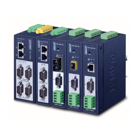
User's Manual of IMG-2x00T Modbus Gateway Series
RS232/RS422/RS485
Industrial Modbus Gateway
IMG-2100T / IMG-2105AT
IMG-2102T / IMG-2102TS
IMG-2200T / IMG-2400T
1
Table of
Contents
Previous
Page
Next
Page
1
2
3
4
5
Advertisement
Table of Contents
Need help?
Do you have a question about the IMG-2100T and is the answer not in the manual?
Ask a question
Questions and answers
Related Manuals for Planet IMG-2100T
Gateway Planet IG-100 User Manual
Internet gateway (78 pages)
Gateway Planet ICG-2420-LTE Quick Installation Manual
Industrial 4g lte cellular gateway (12 pages)
Gateway Planet ISG-101 User Manual
Internet subscriber gateway (29 pages)
Gateway Planet IMG-110T Quick Installation Manual
Industrial rs422/485 modbus gateway (16 pages)
Gateway Planet IMG-110T User Manual
Industrial 1-port rs422/485 modbus (70 pages)
Gateway Planet ICG-2510W-LTE Series User Manual
Industrial 4g lte cellular wireless gateway with 5-port 10/100/100t (95 pages)
Gateway Planet ICG-2510W-LTE Quick Installation Manual
Industrial 4g lte cellular wireless gateway with 5-port 10/100/1 ooot (12 pages)
Gateway Planet IMG-2105AT User Manual
Rs232/rs422/rs485 industrial modbus gateway (70 pages)
Gateway Planet IMG-2200T User Manual
Rs232/rs422/rs485 industrial modbus gateway (70 pages)
Gateway Planet IMG-2400T User Manual
Rs232/rs422/rs485 industrial modbus gateway (70 pages)
Gateway Planet ICG-2515-NR Series User Manual
Industrial 5g nr cellular gateway (129 pages)
Gateway Planet ICG-2515 Series Quick Installation Manual
Industrial 5g nr cellular gateway (15 pages)
Gateway Planet IVR-100 Series User Manual
Industrial 5-port 10/100/1000t vpn security gateway (146 pages)
Gateway Planet VIP-1680 Series User Manual
2-24 port h.323/sip voip gateway (91 pages)
Gateway Planet VIP-000 User Manual
Internet telephone gateway (130 pages)
Gateway Planet MH-4000 User Manual
Multi-homing security gateway (239 pages)
This manual is also suitable for:
Img-2105at
Img-2102t
Img-2102ts
Img-2200t
Img-2400t
Table of Contents
Print
Rename the bookmark
Delete bookmark?
Delete from my manuals?
Login
Sign In
OR
Sign in with Facebook
Sign in with Google
Upload manual
Upload from disk
Upload from URL


Need help?
Do you have a question about the IMG-2100T and is the answer not in the manual?
Questions and answers