Command access MLRK1 Series Insert Instructions
Hide thumbs
Also See for MLRK1 Series:
- Insert instructions (7 pages) ,
- Instructions manual (7 pages) ,
- Installation instructions (5 pages)
Advertisement
Quick Links
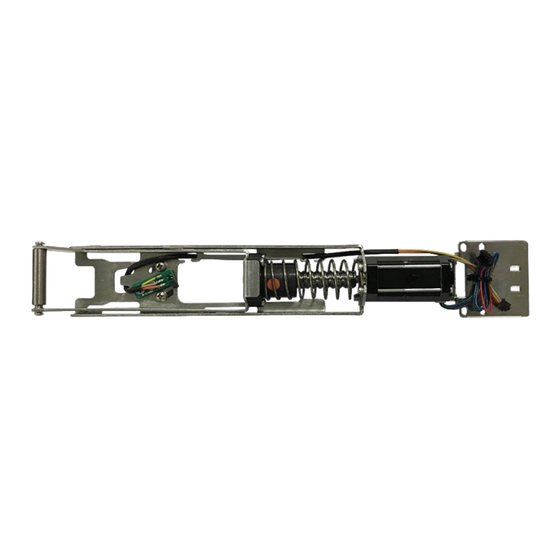
The Command Access MLRK1 is a field-installable motorized latch-retraction kit for:
A.
C.
Ki t I ncl u d e s
A. 60241 – MLRK1 motor
B. 60264 – mm4 module
C. 50453 – magnet bracket
D. 40040 – phillips Screws (x2)
•
Input Voltage: 24VDC +/- 10%
•
Wire gauge: Minimum 18 gauge
•
Direct wire run - no relays or access control units
in-between power supply & module
R e c ommend e d P ow er S u pp li es:
All Command Access exit devices & field installable kits have been thoroughly cycle tested with Command
Access power supplies at our factory. If you plan on using a non-Command power supply it must be a
filtered & regulated linear power supply.
U S c u s t o m e r s u p p o r t 1 - 8 8 8 - 6 2 2 - 2 3 7 7 | w w w . c o m m a n d a c c e s s . c o m | C A c u s t o m e r s u p p o r t 1 - 8 5 5 - 8 2 3 - 3 0 0 2
M L R K 1
INSERT Instructions
• MLRK1-JAC 12 - Jackson 1285, 1286 and 1295 series devices
• MLRK1-KAW17 - Kawneer 1686 and 1786 series devices
• MLRK1-AHT - AHT 8 and 9 series devices
E.
D.
F.
E. 40059 – cable mounting pad
F. 40060 – cable tie
G. 50636 – Cable guides (x3)
H. 50436 – 8' Power cable
SPECIFICATIONS
G.
T oo l s R eq uir e d
• cordless drill
(x2)
• 1/16" Drill bit
• minor cutting tools and file
• #0 phillips screwdriver
• #2 phillips screwdriver
Standard Torque Mode
Average Latch Retraction Current: 1.3 Amp
Average Holding Current: 215 mA
High Torque Mode
Average Latch Retraction Current: 2 Amp
Average Holding Current: 250 mA
1
B.
H.
# 2 0 3 7 9 _ L
Advertisement

Related Manuals for Command access MLRK1 Series


Summary of Contents for Command access MLRK1 Series
- Page 1 R e c ommend e d P ow er S u pp li es: All Command Access exit devices & field installable kits have been thoroughly cycle tested with Command Access power supplies at our factory. If you plan on using a non-Command power supply it must be a filtered &...
-
Page 2: Technical Information
Technical Information GREEN CHANNEL 1 Ceiling Tile NORMALLY OPEN DRY CONTACT FROM ACCESS CONTROL SYSTEM NO VOLTAGE LOCKING HARDWARE Scan me for more information Module Setting PTS **Important Info** Make sure to set PTS before finishing installation MM4 SWITCHES Select your preferred torque mode (ships in standard torque). Press the Step 1 - STANDARD TORQUE device push pad to the desired setting. - Page 3 installation instructions Remove the Front and Back End Caps, which are held on by four screws (two each). Front End Cap Back End Cap Material will need to be removed from the Back End Cap. Before: After: Drill pilot hole on top corner 5/8”...
- Page 4 installation instructions Flip the device back over and slide the Push Pad to the right, exposing the Front Activating Bracket. *Move the Push Pad slowly as some Front Activating Bracket pieces are held in by the Push Pad and tend to fall out when exposed. Push Pad With the Front Activating Bracket exposed, remove the Guides, Thin Clear Washers and Roll Pin.
- Page 5 installation instructions Reinstall the Head Assembly. Head Assembly Flip the Push Pad over and remove the Dogging Assembly underneath (four screws). Dogging Assembly Install the Magnet Bracket by first hooking the bottom tab under the Front Activating Bracket. Then press on the top plane to snap the Magnet Bracket in place. Press Here Once snapped in place, tighten the Top Screw to secure the Bracket in position.
- Page 6 installation instructions Remove the four screws from the Bottom Dogging Bracket, keep the Bracket in place. Bottom Dogging Bracket Flip MLRK1 over and angle the Scissor Bracket to match the position shown below. Scissor Bracket To install the MLRK1, slide the Rolling Guide over the Front Activating Bracket. Then place the Rear Mounting Bracket over the Bottom Dogging Bracket as shown below.
-
Page 7: Installation Instructions
installation instructions If you are installing the MLRK1 into a Jackson series device: • Use the Front screw hole locations on the Rear Mounting Bracket and align with the front holes on the Base Rail. If you are installing the MLRK1 into a Kawneer or AHT series device: •... - Page 8 installation instructions Next, slide the Module Bracket into the Channel at the bottom of the Base Rail. (Back of Base Rail) Channel Module Bracket Line up the edge of the Module Bracket to the machining mark on the Base Rail, then tighten all four screws.
- Page 9 installation instructions Install the Cable Guides as shown, then press the Module Wiring Harness into them. Reassmble the Front and Back Activating Brackets by: • First sliding the Rolls Pins into the brackets • Then placing the two Connecting Rods on the Roll Pins as shown •...
- Page 10 installation instructions *IMPORTANT* After reinstalling the Rear End Cap and its two screws, double check to make sure the Module Wiring Harness is in the Cut Out and not being hit by the Rear End Cap. Push Pad down, Wiring Harness within Cut Out Rear End Cap Cut Out Make sure to set PTS before finishing installation MM4 SWITCHES...
Need help?
Do you have a question about the MLRK1 Series and is the answer not in the manual?
Questions and answers