Table of Contents
Advertisement
Quick Links
The Command Access
pullback kit for the Jackson 1285/95 & AHT 8/9 series devices.
A.
D.
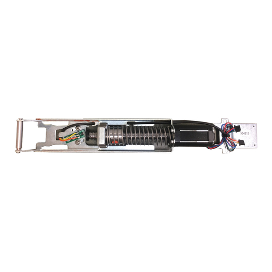
KIT IN C LU D ES
A.
1-
60241 Motor Mount
B.
1-
60264 MM4 RM series module (w/ optional REX)
C.
2-
40040 Phillips Screws
D.
1-
50453 Bracket
E.
2-
40059 Cable Mounting Pad
F.
3-
50636 Cable Guides
G.
2-
40060 Cable Ties
1-
H.
50741 MM4 RM Cable
1-
I.
50436 8' Lead
U S c u s t o m e r s u p p o r t 1 - 8 8 8 - 6 2 2 - 2 3 7 7 | w w w . c o m m a n d a c c e s s . c o m | C A c u s t o m e r s u p p o r t 1 - 8 5 5 - 8 2 3 - 3 0 0 2
PD15-UL-M KIT
INSTR UCTIONS
PD15-UL-M-KIT
E.
F.
is a field-installable motorized latch-
B.
G.
|
TO OL S R E QU I R E D
Cordless Drill
1/16" drill bit
File
#2 Phillips head screwdriver
PH-00 Screwdriver
C.
H.
I.
Watch the Video
# 2 0 3 7 9 _ J
Advertisement
Table of Contents

Related Manuals for Command access PD15-UL-M


Summary of Contents for Command access PD15-UL-M
- Page 1 PD15-UL-M KIT INSTR UCTIONS The Command Access PD15-UL-M-KIT is a field-installable motorized latch- pullback kit for the Jackson 1285/95 & AHT 8/9 series devices. KIT IN C LU D ES TO OL S R E QU I R E D...
- Page 2 Technical Information SPECIFICATIONS • Input Voltage: 24VDC +/- 10% • Wire gauge: Minimum 18 gauge MM4 Switches Standard Torque Mode • Direct wire run - no relays or STANDARD TORQUE Average Latch Retraction Current: 1 Amp access control units in-between HIGH TORQUE Average Holding Current: 215 mA PTS PROGRAMMING ON...
- Page 3 Legend Standard Placement ecommended oweR uPPlieS All Command Access exit devices & field installable kits have been thoroughly cycle tested with Command Access power supplies at our factory. For more information click here or go to our website U S c u s t o m e r s u p p o r t 1 - 8 8 8 - 6 2 2 - 2 3 7 7 | w w w . c o m m a n d a c c e s s . c o m | C A c u s t o m e r s u p p o r t 1 - 8 5 5 - 8 2 3 - 3 0 0 2...
- Page 4 STEP 1 Disassemble Exit Device Remove (2) screws on push pad end caps from Pull back push pad exposing the front activating brack- front & back et. Remove guides and roll pin from activating bracket. Once connecting rods are disconnected from front Remove head assembly by removing (2) screws.
- Page 5 Re-attach head assembly by securing (2) screws. Next, we’ll be installing the kit in between the activating brackets on the exposed baserail. **Important Info** BEFORE MOVING TO STEP 2 - SEE STEP C on PAGE BEFORE AFTER PILOT HOLE PILOT HOLE IN INCHES (“) AMOUNT REMOVED IN INCHES (“) 1/2”...
- Page 6 Next, drop the motor mount in with the front over the front activating bracket. Line up the back with the (2) available screw holes and the bracket securing the motor mount. Push screws to correct position (pictured) to straighten Tighten back end of the module by re- scissor bracket and secure front end of the motor kit by installing (2) screws from dogging bracket.
- Page 7 Connect MM4 Cable. Attach the strain relief and secure MM4 cable with a zip tie. 1. Attach the wire guides to the inside of the baserail. 2. Route wires along the inside of the baserail using the wire guides. **HOOK UP TO POWER & TEST MOTOR BEFORE MOVING ON TO STEP 5.** STEP 3 Reassemble Exit Device...
- Page 8 Turn over BACK push pad end cap over and start a pilot hole beneath the bottom right hand corner (see measurements below). Use the gold bracket as a guide. Once your hole is drilled use your preferred method to clear out the remaining debris and file to clean up the edges. BEFORE AFTER PILOT HOLE...
Need help?
Do you have a question about the PD15-UL-M and is the answer not in the manual?
Questions and answers