Command access MLRK1 Instructions Manual
Field-installable motorized latch-retraction kit for mlrk1-dor - dorma 9000 series exit devices
Hide thumbs
Also See for MLRK1:
- Insert instructions (10 pages) ,
- Instructions manual (7 pages) ,
- Installation instructions (5 pages)
Table of Contents
Advertisement
Quick Links
The Command Access MLRK1 is a field-installable motorized latch-retraction kit for:
A.
Ki t I ncl u d e s
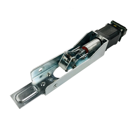
A. 60346 MLRK1-DOR
B. 40802 8-32 x 3/8 SS Screws ( x4 )
C. 50436 8' power lead
•
Input Voltage: 24VDC +/- 10%
•
Wire gauge: Minimum 18 gauge
•
Direct wire run - no relays or access control units
in-between power supply & module
R e c ommend e d P ow er S u pp li es:
All Command Access exit devices & field installable kits have been thoroughly cycle tested with Command
Access power supplies at our factory. If you plan on using a non-Command power supply it must be a
filtered & regulated linear power supply.
U S c u s t o m e r s u p p o r t 1 - 8 8 8 - 6 2 2 - 2 3 7 7 | w w w . c o m m a n d a c c e s s . c o m | C A c u s t o m e r s u p p o r t 1 - 8 5 5 - 8 2 3 - 3 0 0 2
M L R k 1
INSERT Instructions
• MLRK1-DOR - Dorma 9000 series exit devices
SPECIFICATIONS
B.
C.
T o o l s Re qu ir ed
#2 phillips screwdriver
*do not use impact driver
or max torque setting on drill
Standard Torque Mode
Average Latch Retraction Current: 900 mA
Average Holding Current: 215 mA
High Torque Mode
Average Latch Retraction Current: 2 Amp
Average Holding Current: 250 mA
1
# 2 0 4 5 2 _ B
Advertisement
Table of Contents

Related Manuals for Command access MLRK1


Summary of Contents for Command access MLRK1
- Page 1 R e c ommend e d P ow er S u pp li es: All Command Access exit devices & field installable kits have been thoroughly cycle tested with Command Access power supplies at our factory. If you plan on using a non-Command power supply it must be a filtered &...
- Page 2 Technical Information GREEN CHANNEL 1 Ceiling Tile NORMALLY OPEN DRY CONTACT FROM ACCESS CONTROL SYSTEM NO VOLTAGE LOCKING HARDWARE Module Legend Standard Placement Optional Placement Setting PTS **Important Info** Make sure to set PTS before finishing installation MM4 SWITCHES Select your preferred torque mode (ships in standard torque). Press the Step 1 - STANDARD TORQUE device push pad to the desired setting.
- Page 3 installation instructions Remove Head Cover (4 screws) and Head Assembly (2 screws). Head Assembly Head Cover 1 each side Flip the bar over and remove the 6 Screws holding the Pushpad Assembly to the Base Rail. 6 Screws Base Rail Slide Pushpad Assembly and Slide Cover out of the Base Rail.
- Page 4 installation instructions If you would prefer not to have Dogging on your device, simply remove the E-Clip and the Plastic Dogging Piece, Ball Bearing and Metal Bracket can be taken off. E-Clip Metal Bracket Ball Bearing Plastic Dogging E-Clip Flip Pushpad Assembly over and locate the Front Activating Bracket. Front Activating Bracket Pushpad Assembly Remove the E-Clip from the Pin that holds the Mounting Bracket to the Activating Bracket.
- Page 5 Spring Ends Spring Ends Leading End Use your fingers to hold down the Spring Ends and slide the MLRK1-DOR until its cutout aligns with the Activating Bracket’s Pin Hole. Re-install the Pin and secure it with the E-Clip. Slide MLRK1-DOR...
- Page 6 Re-install the Head Assembly (2 screws), Head Cover (4 screws) and Slide Cover. *You may have to turn the plastic dogging piece in order to fully install the Slide Cover. Then, plug the MLRK1-DOR to power and program the Push To Set position following the instructions below, remembering to turn the Programming Switch to the off position when completed.
Need help?
Do you have a question about the MLRK1 and is the answer not in the manual?
Questions and answers