Advertisement
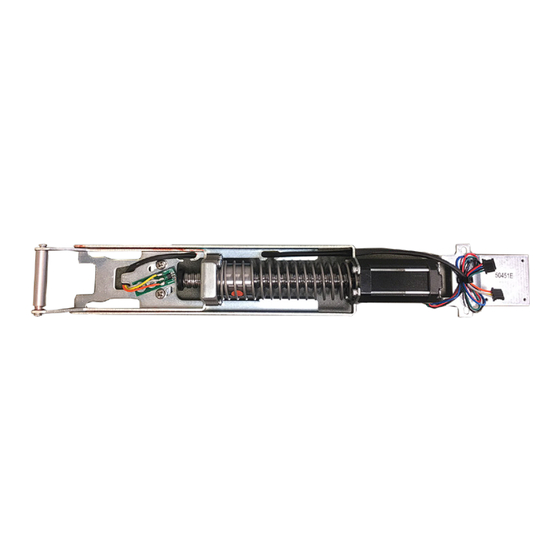
The Command Access MLRK1-KAW17 is a field installable motorized latch-retraction kit for:
A.
D.
KIT INCLU D E s
1 - 60241 Motor Mount
A.
1 - 60264 MM4 RM series module (w/ optional REX)
B.
2 - 40040 Phillips Screws
C.
1 - 50453 Bracket
D.
2 - 40059 Cable Mounting Pad
E.
3 - 50636 Cable Guides
F.
2 - 40060 Cable Ties
G.
1 - 50741 MM4 RM Cable
H.
1 - 50436 8' Lead
I.
R e c ommende d Po wer S u pp lie s :
All Command Access exit devices & field installable kits have been thoroughly cycle tested with Command
Access power supplies at our factory. If you plan on using a non-Command power supply it must be a
filtered & regulated linear power supply.
U S c u s t o m e r s u p p o r t 1 - 8 8 8 - 6 2 2 - 2 3 7 7 | w w w . c o m m a n d a c c e s s . c o m | C A c u s t o m e r s u p p o r t 1 - 8 5 5 - 8 2 3 - 3 0 0 2
MLRK1
INSTRUCTIONS
• MLRK1-KAW17 - Kawneer 1686 & 1786 series devices
• MLRK1-JAC12 - Jackson 1285, 1286 & 1295 series devices
• MLRK1-AHT - AHT 8 & 9 series devices
E.
F.
B.
G.
H.
T O O L S REQ U IRE D
Cordless Drill
1/16" drill bit
File
#2 Phillips head screwdriver
PH-00 Screwdriver
C.
I.
# 2 0 3 7 9 _ K
Advertisement
Table of Contents

Related Manuals for Command access MLRK1-JAC12


Summary of Contents for Command access MLRK1-JAC12
- Page 1 R e c ommende d Po wer S u pp lie s : All Command Access exit devices & field installable kits have been thoroughly cycle tested with Command Access power supplies at our factory. If you plan on using a non-Command power supply it must be a filtered &...
- Page 2 Technical Information GREEN CHANNEL 1 NORMALLY OPEN DRY CONTACT FROM ACCESS CONTROL SYSTEM NO VOLTAGE LOCKING HARDWARE Ceiling Tile Legend Standard Placement Setting PTS **Important Info** Make sure to set PTS before finishing installation Select your preferred torque mode (ships in standard torque). Press the Step 1 - MM4 SWITCHES device push pad to the desired setting.
- Page 3 STEP 1 Disassemble Exit Device Remove (2) screws on push pad end caps from front & back. Pull back push pad, exposing the front activating bracket. Remove guides and roll pin from activating bracket. Once connecting rods are disconnected from front activating bracket Remove head assembly by removing (2) screws.
- Page 4 Re-attach head assembly by securing (2) screws. Next, we’ll be installing the kit in between the activating brackets on the exposed baserail. **Important Info** BEFORE MOVING TO STEP 2 - SEE STEP 3 on PAGE BEFORE AFTER PILOT HOLE PILOT HOLE IN INCHES (“) AMOUNT REMOVED IN INCHES (“) 1/2”...
- Page 5 Next, drop the motor mount in with the front over the front activating bracket. Line up the back with the (2) available screw holes and the bracket securing the motor mount. Push screws to correct position (pictured) to straighten scissor bracket and Tighten back end of the module by re-installing (2) screws secure front end of the motor kit by tightening (2) screws.
- Page 6 Connect MM4 Cable. Attach the strain relief and secure MM4 cable with a zip tie. 1. Attach the wire guides to the inside of the baserail. 2. Route wires along the inside of the baserail using the wire guides. **HOOK UP TO POWER & TEST MOTOR BEFORE MOVING ON TO STEP 5.** STEP 3 Reassemble Exit Device...
- Page 7 Turn over BACK push pad end cap over and start a pilot hole beneath the bottom right hand corner (see measurements below). Use the gold bracket as a guide. Once your hole is drilled use your preferred method to clear out the remaining debris and file to clean up the edges. BEFORE AFTER PILOT HOLE...
Need help?
Do you have a question about the MLRK1-JAC12 and is the answer not in the manual?
Questions and answers