Advertisement
m l r k 1 - m r k / d h
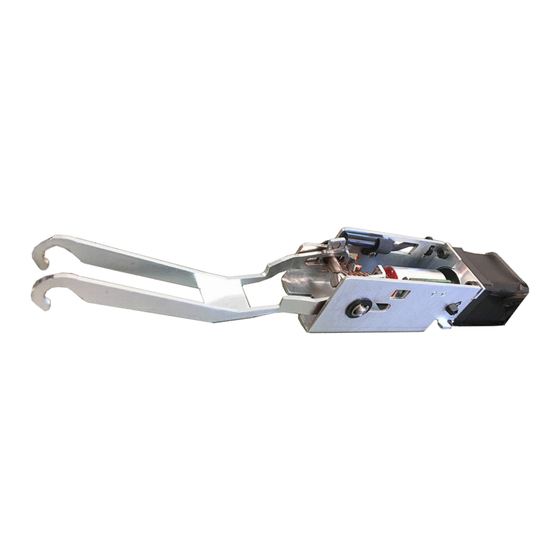
The Command Access MLRK1-MRK is a field installable motorized latch-retraction kit for:
• MLRK1-MRK - Marks M9900 & M8800 series devices
• MLRK1-DH - Design Hardware 1000 series device
A.
B.
Ki t I ncl u d e s
1- 60280 Motor Mount w/ MM4T series module
A.
2- 40706 Phillips head screws
B.
1- 50030 8' Lead w/ VD Connector
C.
1- 50944 MM4T Socket Lead
D.
1- 40707 Thread locking Flat tip Set Screw 8/32"
E.
1- 40114 Dogging Hole Cap
F.
•
Input Voltage: 24VDC +/- 10%
•
Wire gauge: Minimum 18 gauge
•
Direct wire run - no relays or access control units in-between
power supply & module
R e co mm e nd ed Power Su ppli es:
All Command Access exit devices & field installable kits have been thoroughly cycle tested with Command Access power supplies at our factory. If you plan
on using a non-Command power supply it must be a filtered & regulated linear power supply.
C o m m a n d A c c e s s Te c h n o l o g i e s | 2 2 9 0 1 L a P a l m a A v e , Yo r b a L i n d a , C A 9 2 8 8 7 | P h o n e : ( 8 8 8 ) 6 2 2 - 2 3 7 7
INSERT Instructions
C.
D.
SPECIFICATIONS
1
E.
F.
T o o l s Re qu ir ed
• Cordless Drill
• (M8800) 8/32 Tap
• (M8800) 2mm Hex Wrench
Standard Torque Mode
Average Latch Retraction Current: 900 mA
Average Holding Current: 215 mA
High Torque Mode
Average Latch Retraction Current: 2 Amp
Average Holding Current: 250 mA
# 2 0 4 0 9 _ E
Advertisement
Table of Contents

Related Manuals for Command access MLRK1-MRK


Summary of Contents for Command access MLRK1-MRK
- Page 1 R e co mm e nd ed Power Su ppli es: All Command Access exit devices & field installable kits have been thoroughly cycle tested with Command Access power supplies at our factory. If you plan on using a non-Command power supply it must be a filtered & regulated linear power supply.
- Page 2 Technical Information Setting PTS **Important Info** Make sure to set PTS before finishing installation MM4T SWITCHES Select your preferred torque mode (ships in standard torque). Press the Step 1 - STANDARD TORQUE device push pad to the desired setting. (We recommend to fully depress HIGH TORQUE and release 5%, giving the device room for changing door conditions.) PTS PROGRAMMING ON...
- Page 3 Installation Instructions M9900 O M8800 n ly s k i p t o p a g e Remove head cover & Slide off housing, exposing the Remove (2) Pins securing push pad to baserail. baserail. Pins Flip over push pad, exposing activating brackets. Pull activating bracket over onto spring and hold in place.
- Page 4 CONTINUED Flip pushpad over with kit hooked in & Reinstall (2) pins to secure push pad to baserail. Pins Pins Flip baserail & push pad over to secure motor mount with (2) screws provided. Slide baserail into housing making sure the baserail slides into the cor- rect channel.
- Page 5 CONTINUED M8800 Installation Only Remove head cover & Slide off housing exposing the baserail. Remove (2) Pins securing push pad to baserail. Pins Using 8/32” tap, tap center hole on baserail in-between 4 holes. Install thread locking flat tip set screw into center hole by hand. OPEN SIDE facing down.
- Page 6 Remove (2) screws on the left to remove back activating bracket. Slide Push pad cover off just enough to reveal back (4) screws on push pad. SCREWS Remove pin from activating bracket then remove the (2) spacers on each side & discard. Next, re-insert pin into activating bracket. Place back activating bracket back into the push pad &...
- Page 7 Holding activating bracket in place, grab motor kit & hook onto the pin on the outside of the activating bracket. Next, rotate motor kit 180 degrees to the back of the push pad. ACTIVATING BRACKET PIN BACK OF PUSH PAD Flip push pad over with kit hooked in &...
- Page 8 Next, plug into power supply and test device. Once power is achieved, follow steps for set the push to set (PTS), remembering to turn the Programming Switch to the off position when completed. Setting PTS **Important Info** Make sure to set PTS before finishing installation Select your preferred torque mode (ships in standard torque).
Need help?
Do you have a question about the MLRK1-MRK and is the answer not in the manual?
Questions and answers