
Related Manuals for Command access PD15


Summary of Contents for Command access PD15
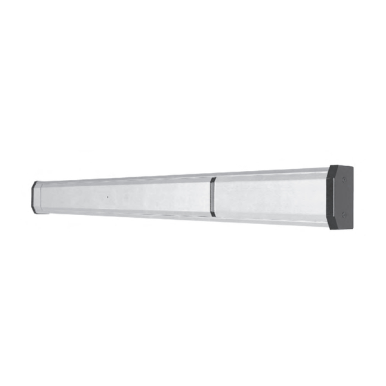
- Page 1 Installation Instructions PD15 CVR Exit Device Read all instructions completely before beginning.
- Page 2 Step #1 Prepare lock stile.
- Page 3 Step #2 Install Rod & Case assembly into active stile. Secure with 2 ea. 8-32 x 1/4 cap screws. Install spacer per drawing.
- Page 4 Step #3 Install Top & Bottom Strikes. Secure with 2 ea. 8-3/4(19) self tap screws.
- Page 5 NOTE: If trim or cylinder are Step #4 not being used, skip this step. Install Trim and Cylinder. Install one 8-32 pan head screw partially to suit nominal wall thickness of 1/8” or 3/16” Install pad assembly and rotate clockwise until it locks into position. Install single 8-32 x 1-15/16”...
- Page 6 Step #5 Panic Attachment. - Remove front and rear end base covers by releasing 6-32x3/16(5) & 12-24x1-1/4(32) fillister head screw through chassis and one 8-32x1-1/4 head machine screw, secure inactive end with single 1/4-20x1/2(13) round head machine screw (phil.) with semsthrough inactive base plate. - Using the wire access hole as a guide, drill a 3/8"...
- Page 7 Step #6 Adjust Top & Bottom Bolts. Adjust Top & Bottom Bolts allowing for 1/2”(13) of bolt to extend from vertical stile. Install bolt guides top & bottom with (2) each #10x1/2(13) flat head self-tapping screws. Depress push bar, top bolt should lock in the retracted (unlocked) position. If locking does not occur readjust bolts in half turn increments until locking occurs.
- Page 8 Step #7 PWM202 HO Wiring Instructions Specifications Operating Voltage: 26.5V +/- 15% Input Wires to PWM202HO: Red (+), Black (-) Output Wires from PWM202HO: Yellow (+), Green (-) Power Supply: PS1N Wire Run Guidelines: For best results we recommend that your maximum wire run not exceed the following: 18ga.= 700’...
Need help?
Do you have a question about the PD15 and is the answer not in the manual?
Questions and answers