
Related Manuals for Lantronix Intrinsyc Open-Q 865XR SOM


Summary of Contents for Lantronix Intrinsyc Open-Q 865XR SOM
- Page 1 Open-Q™ 865XR SOM Development Kit User Guide Part Number PMD-00028 Revision A August 2020...
-
Page 2: Contacts
Phone: 949-453-3990 Fax: 949-453-3995 IES Support Support: https://helpdesk.intrinsyc.com Lantronix Technical Support Online: http://www.lantronix.com/support Sales Offices For a current list of our domestic and international sales offices, go to the Lantronix web site at http://www.lantronix.com/about-us/contact/ Open-Q 865XR SOM Development Kit User Guide... -
Page 3: Revision History
Revision History Date Rev. Comments August 2020 Preliminary Initial Lantronix document For the latest revision of this product document, please go to: http://tech.intrinsyc.com. Open-Q 865XR SOM Development Kit User Guide... -
Page 4: Table Of Contents
Table of Contents Contacts _________________________________________________________________ 2 Revision History ___________________________________________________________ 3 Table of Contents __________________________________________________________ 4 List of Figures _____________________________________________________________ 6 List of Tables _____________________________________________________________ 6 1 Introduction Purpose ___________________________________________________________ 7 Scope _____________________________________________________________ 7 Intended Audience ___________________________________________________ 7 2 Documents Applicable Documents ________________________________________________ 8 Reference Documents ________________________________________________ 8 Terms and Acronyms _________________________________________________ 8 3 Open-Q 865XR SOM Development Kit... - Page 5 3.7.13 Display Connector J1300 (38) _____________________________________ 28 3.7.14 Camera Connectors J1000 (15), J1100 (16), J1200 (17) _________________ 29 3.7.15 Camera option Connectors J1001 (18), J1101 (19), J1201(20) ____________ 30 3.7.16 M.2 PCIe Card Connector J2700 (24) _______________________________ 30 3.7.17 Digital IO Expansion Header J2100 (23) _____________________________ 32 3.7.18 Sensor IO Expansion Header J2000 (21) ____________________________ 33 3.7.19...
-
Page 6: List Of Figures
List of Figures Figure 1. Assembled Open-Q 865XR SOM Development Kit ............11 Figure 2. Open-Q 865XR SOM Dev Kit Block Diagram ..............14 Figure 3. DIP switch assignments ....................18 Figure 4. Input Power Selection Locations ..................19 Figure 5. SOM Current Sense Header J301 (5) ................21 Figure 6. -
Page 7: Introduction
Purpose The purpose of this user guide is to provide instructions and technical information on the Open-Q 865XR SOM Development Kit. You can find information on this and other Lantronix development kits on the Lantronix web site: http://www.lantronix.com/products Scope This document will cover the following items on the Open-Q 865XR SOM Development Kit: Block Diagram and Overview •... -
Page 8: Documents
2: Documents 2 Documents This section lists the supplementary documents for the Open-Q 865XR SOM Development Kit. Applicable Documents REFERENCE TITLE Intrinsyc License and Purchase Terms and Conditions for the Open-Q 865XR Reference Documents The below listed documents are available on the Technical Portal: https://tech.intrinsyc.com (dev kit registration required) - Page 9 2: Documents FWVGA Full Wide Video Graphics Array Global Positioning system HDMI High Definition Media Interface HSIC High Speed Inter Connect Bus JTAG Joint Test Action Group Low Noise Amplifier MIPI Mobile Industry processor interface Multi-Purpose Pin Near Field Communication Qualcomm Universal Peripheral (Serial interfaces like UART / SPI / I2C/ UIM) Radio Frequency...
-
Page 10: Open-Q 865Xr Som Development Kit
3: Open-Q 865XR SOM Development Kit 3 Open-Q 865XR SOM Development Kit Introduction The Open-Q 865XR provides a quick reference and evaluation platform for the Qualcomm SXR2130P Platform. The development kit is suited for Android application developers, OEMs, consumer manufacturers, hardware component vendors, camera vendors, and product designers to evaluate, optimize, test and deploy applications that can utilize the Qualcomm SXR2130P Platform technology. -
Page 11: Important Locations
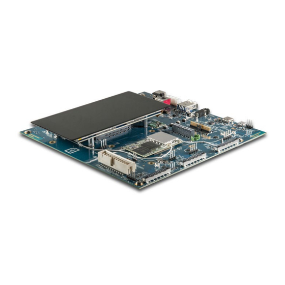
3: Open-Q 865XR SOM Development Kit 3.4.1 Important Locations The diagram below shows the locations of key components, interfaces, and controls. Figure 1. Assembled Open-Q 865XR SOM Development Kit Open-Q 865XR SOM Development Kit User Guide... -
Page 12: Table 1. List Of Development Kit Features Itemized In The Figure Above
3: Open-Q 865XR SOM Development Kit Table 1. List of Development Kit Features itemized in the figure above Position Feature Description Reference Designator DC Power Supply Jack J400 Power Source Selector S300 Battery Input Header J300 Battery Configuration DIP Switch S301 USB 3.1 Type A Connector J2300... - Page 13 3: Open-Q 865XR SOM Development Kit Position Feature Description Reference Designator M.2 PCIe Card Connector (on bottom side of Carrier Board) J2700 SIM Card Socket for M.2 PCIe (on bottom side of Carrier J2701 Board) Audio Outputs Expansion J1801 Audio Inputs Expansion J1800 Audio Codec Module (on top side of Carrier Board underneath U1600...
-
Page 14: Block Diagram
3: Open-Q 865XR SOM Development Kit 3.4.2 Block Diagram The block diagram below shows the connectivity and major components of the Open-Q 865XR SOM Development Kit. OpenQ865 SOM DEVKIT OpenQ865 SOM DEVKIT VBUS Power PM8150L RGB_RED OpenQ865 uSOM PM8150L RGB_GRN EBI0/EBI1 PM8150L RGB_BLU LPDDR5 6GB Micron... -
Page 15: Getting Started
3: Open-Q 865XR SOM Development Kit accessories: https://shop.intrinsyc.com/collections/accessories, or contact sales@lantronix.com. Getting Started This section explains how to setup the Open-Q 865XR SOM Development Kit and start using it. 3.5.1 Registration To register the development kit and gain access to the Intrinsyc Technical Document Portal, please visit: http://tech.intrinsyc.com/account/register. -
Page 16: Open-Q 865Xr Som
3: Open-Q 865XR SOM Development Kit Open-Q 865XR SOM The Open-Q 865XR SOM contains the core 865 architecture. Measuring in at 50mm x 29mm, the SOM is where all the processing occurs. It is connected to the carrier board via two 100 pin and one 120 pin Hirose DF40 connectors which allows essential power rails and signals to be exposed for supporting other peripherals and interfaces on the platform. - Page 17 3: Open-Q 865XR SOM Development Kit Item Position Description Specification Usage Sensor Connector 24 pin Sensor Expansion Available via Lantronix Connector optional accessories kit Digital IO Expansion Exposes general purpose IO for Header user development Audio Headset Jack Audio Headset Jack...
-
Page 18: Som Board To Board Connectors (33)
3: Open-Q 865XR SOM Development Kit Item Position Description Specification Usage be used by the dev kit user. Current Sense 3 pin header Sense lines connected To measure current Header (VPH_PWR) across 0.005 Ohm consumption of resistor SOM_VPH_PWR Current Sense 3 pin header Sense lines connected To measure current... -
Page 19: Input Power Selection
SOM when power is auto boot of the SOM applied. when power is applied, set switch closed / ON. For factory mode For Lantronix use only. FORCED_USB_BOOT J2500 programming. Connected Leave open. to CPU GPIO132. 3.7.3 Input Power Selection The development kit can be powered using either external DC power supply or by using a battery. -
Page 20: Table 4. Battery Id / Thermistor Configuration Dip Switch Settings
3: Open-Q 865XR SOM Development Kit 3.7.3.1 Input Power Selection Switch S300 (2) The S300 switch shown in the figure above is used to select the power source. To select the external DC power supply as the power source, slide the switch towards the ‘12V’ position. To power up the kit using the battery, slide the switch towards the ‘BATT’... -
Page 21: Current Sense Header J301 (35) And J901 (39)
3: Open-Q 865XR SOM Development Kit Table 5. Battery Connector J300 Pinout Pin No Signal Description System ground, Battery Negative Wire System ground, Battery Negative Wire BATT_THERM_CONN 100K Thermistor BATT_ID_CONN ID Resistor (optional) VBATT_CONN Battery Positive Wire VBATT_CONN Battery Positive Wire 3.7.4 Current Sense Header J301 (35) and J901 (39) The SOM Current Sense header, J301, can be used to monitor the SOM + CB VPH_PWR current consumption on the main SOM_SYS_PWR power rail. -
Page 22: Figure 6. Vph Current Sense Header J901 (39)
3: Open-Q 865XR SOM Development Kit The table below summarizes the pin outs of header J301 Table 6. Power Header J301 Pinout Pin No Signal Description SOM_PWR_SENSE_P SOM power positive current sense line SOM_PWR_SENSE_N SOM power negative current sense line System Ground To obtain power consumption measurements, the header is connected to a data acquisition unit (Keithley 2701 or similar) and the voltages on the SOM_PWR_SENSE_P/N pins are captured a few times a... -
Page 23: Coin Cell Battery Holder B300 (30)
3: Open-Q 865XR SOM Development Kit To obtain power consumption measurements, the header is connected to a data acquisition unit (Keithley 2701 or similar) and the voltages on the VPH_PWR_SENSE_P/N pins are captured a few times a second over the test period (typically 30 minutes). The SOM power consumption is then calculated as (where Rsense = 5 milliohms): (������������ℎ... -
Page 24: Table 8. Power Header J700 (29)
3: Open-Q 865XR SOM Development Kit Table 8. Power Header J700 (29) Signal Description Signal Description +1.1V Carrier Board LDO +2.85V Carrier MB_ELDO_CAM0_DVDD_1P1 for Camera 1 MB_ELDO_CAM0_VCM_2P85 Board LDO for DVDD, Camera 1 VCM Camera core +1.2V SOM Board power VREG_L1F_1P2 for Camera 1 System Ground... -
Page 25: User Buttons And Leds (7, 36, 41, 42)
3: Open-Q 865XR SOM Development Kit Signal Description Signal Description +1.8V Carrier +3.3V Carrier Board Buck Board buck- Power boost power MB_VREG_1P8 MB_VREG_3P3 Supply for supply for general general +3.3V +1.8V rail rail +5.0V Carrier Board Boost Main +12.0V Power MB_VREG_5P0 DC_IN_12V Power from DC... -
Page 26: Debug Serial Uart Over Usb J1500 (12)
3: Open-Q 865XR SOM Development Kit Reference Function Designator DS2401 Green LED General purpose LED DS2402 Red LED General purpose LED DS2404 Green LED LED indicates input power DS2403 Green LED LED indicates boot state. This LED is controlled via GPIO_15 with is shared with the Sensor Header (see section 3.7.18). -
Page 27: Usb 3.1 Type A Connector J2300 (5)
3: Open-Q 865XR SOM Development Kit adb shell on the PC prompt to exercise the adb shell functionality. While ADB utilizes only the high-speed channel, this USB type C connector supports the USB 3.1 specification including the super speed data channel. -
Page 28: Display Connector J1300 (38)
The 100-pin display connector, J1300, allows for an optional display adapter to be connected to the development kit. Lantronix offers a compatible LCD panel accessory for the Open-Q 865XR SOM Development Kit. It can be purchased by contacting sales: http://www.lantronix.com/about-us/contact/. -
Page 29: Camera Connectors J1000 (15), J1100 (16), J1200 (17)
J1200 allowing users to connect multiple camera adapters to the development kit. See items 15 through 17 in Figure 1 for the carrier board locations of the camera connectors. Lantronix offers compatible camera module accessories for the Open-Q 865XR SOM Development Kit here: https://shop.intrinsyc.com/collections/accessories... -
Page 30: Camera Option Connectors J1001 (18), J1101 (19), J1201(20)
3: Open-Q 865XR SOM Development Kit 3.7.15 Camera option Connectors J1001 (18), J1101 (19), J1201(20) In addition to the three camera connectors, the video capturing subsystem of the Open-Q 865XR SOM Development Kit is equipped with three connectors for camera optional signals (J1001, J1101 and J1201). -
Page 31: Figure 10. M.2 Pcie And Optional Sim Card Sockets
3: Open-Q 865XR SOM Development Kit Figure 10. M.2 PCIe and Optional SIM Card Sockets The M.2 PCIe card socket supports 30, 42, 60, and 80mm length PCI Express M.2 cards with the 4 mounting holes located below J2700 in the image above. The pinout of J2700 complies with the PCI Express M.2 card standards. -
Page 32: Digital Io Expansion Header J2100 (23)
3: Open-Q 865XR SOM Development Kit PCIe USB Enable DIP Switch (6). If the DIP switch is closed, the USB 3.1 Type A connector J2300 (5) is not functional. Pin 25 of the M.2 Socket connects to GPIO_117. GPIO_117 is shared with general purpose user •... -
Page 33: Sensor Io Expansion Header J2000 (21)
3: Open-Q 865XR SOM Development Kit Signal Description Signal Description Carrier board switching No Net No Net MB_VREG_5P0 regulator +5.0V For more details regarding configuring the GPIOs on this header, refer to the Open-Q 865XR Software Release Notes to determine feature support in the latest software release. 3.7.18 Sensor IO Expansion Header J2000 (21) The Open-Q 865XR SOM Development Kit includes a sensor expansion header J2000 which provides a... -
Page 34: Audio Inputs Expansion Header J1800 (27)
3: Open-Q 865XR SOM Development Kit (SSC0_I2C_SDA GPIO_161 / GPIO_161_SNS_I3C0_SC SSC1 GPIO_129_PRESS_INT GPIO129 (SSC0_I2C_SCL) GPIO_167 / GPIO_165 / GPIO_167_SNS_SPI2_CS SSC7 GPIO_165_SNS_SPI2_M SSC5 (SSC2_SPI0_CS (SSC2_SPI0_MO GPIO_166 / GPIO_164 / GPIO_166_SNS_SPI2_CL SSC6 GPIO_164_SNS_SPI2_M SSC4 (SSC2_SPI0_CL (SSC2_SPI0_MIS GPIO_122_ALSP_INT_N GPIO122 GPIO_64_SAR_INT_N GPIO64 For more details regarding configuring the GPIOs on this header, refer to the Open-Q 865XR SOM Software Release Notes to determine feature support in the latest software release. -
Page 35: Audio Outputs Expansion Header J1801 (26)
3: Open-Q 865XR SOM Development Kit Signal Description Signal Description Carrier board switching CDC_MIC_BIAS4 Microphone Bias 4 MB_VREG_3P3 regulator +3.3V System Ground System Ground Digital Microphone 3 Digital Microphone 4 CDC_DMIC_CLK3 CDC_DMIC_CLK4 Clock Clock CDC_DMIC_DATA Digital Microphone 3 CDC_DMIC_DATA Digital Microphone 4 Data Data SOM LDO Regulator S4A... -
Page 36: Audio Io Expansion Header J1900 (10)
3: Open-Q 865XR SOM Development Kit Signal Description Signal Description Speaker Amp Enable Speaker Amp Enable SOM LDO Regulator Voltage from DC VREG_S4A_1P8 DC_IN_12V S4A +1.8V Power Input +12.0V Carrier board switching MB_VREG_5P0 System Ground regulator +5.0V For more details regarding configuring the GPIOs on this header, refer to the Open-Q 865XR Software Release Notes to determine feature support in the latest software release. - Page 37 3: Open-Q 865XR SOM Development Kit Signal Description Signal Description CPU GPIO146 – can be GPIO_146_LPI_ configured as System Ground MI2S0_CLK LPI_MI2S0_SCK CPU GPIO147 – can be CPU GPIO156 – can be GPIO_147_LPI_ GPIO_156_LPI_ configured as configured as MI2S0_WS MI2S2_CLK LPI_MI2S0_WS LPI_MI2S_CLK CPU GPIO148 –...
-
Page 38: Audio Headset Jack J1700 (8)
3: Open-Q 865XR SOM Development Kit Signal Description Signal Description System Ground No Net No Net 1. Population option changes are necessary in order to use this signal. See the carrier board schematic (R-3) for more details. For more details regarding configuring the GPIOs on this header, refer to the Open-Q 865XR Software Release Notes to determine feature support in the latest software release.
Need help?
Do you have a question about the Intrinsyc Open-Q 865XR SOM and is the answer not in the manual?
Questions and answers