
Related Manuals for Lantronix Open-Q 410


Summary of Contents for Lantronix Open-Q 410
- Page 1 Open-Q™ 410 Development Kit User Guide Part Number PMD-0058 Revision A August 2020...
- Page 2 Phone: 949-453-3990 Fax: 949-453-3995 IES Customer Support Portal https://helpdesk.intrinsyc.com Lantronix Technical Support http://www.lantronix.com/support Sales Offices For a current list of our domestic and international sales offices, go to the Lantronix web site at http://www.lantronix.com/about-us/contact/ Open-Q 410 Dev Kit User Guide...
- Page 3 Added note about SW support for battery charging in section 4.3 August 2020 Initial Lantronix document. Added Lantronix document part number, Lantronix logo, branding, contact information, and links. For the latest revision of this product document, please go to: http://tech.intrinsyc.com.
-
Page 4: Table Of Contents
JTAG Header ______________________________________________________ 32 4.11 Audio Connectors ___________________________________________________ 33 4.11.1 Audio 3.5mm Jacks _____________________________________________ 33 4.11.2 Speaker Connectors ____________________________________________ 34 4.11.3 Digital Mic Header ______________________________________________ 35 4.12 Other Interfaces ____________________________________________________ 36 4.13 System Auto Boot __________________________________________________ 36 Open-Q 410 Dev Kit User Guide... - Page 5 Figure 1 – Assembled Open-Q 410 Development Kit ..............10 Figure 2 – Open-Q™ 410 Development Kit Block Diagram (Rev 0100 shown here) ....12 Figure 3 – Top View of Open-Q 410 SOM ..................16 Figure 4 – Bottom View of Open-Q 410 SOM ................16 Figure 5 –...
-
Page 6: Introduction
410 Development Kit Display Board Design Guide Tech Note Open- Q 410 Development Kit Camera Board Design Guide Tech Note Open- Q 410 Development Kit Carrier Board Design Guide Tech Note Open- Q 410 SOM Development Kit HW Revision Guide Open-Q 410 Dev Kit User Guide... -
Page 7: Terms And Acronyms
SATA Serial ATA SLIMBUS Serial Low-power Inter-chip Media Bus Smart Mobility ARChitecture Specification SMARC - Published by Standardization Group for Embedded Technologies System-On-Module System Power Management Interface SPMI (QUALCOMM PMIC / baseband proprietary protocol) Open-Q 410 Dev Kit User Guide... - Page 8 1: Introduction Term and acronyms Definition UART Universal Asynchronous Receiver Transmitter User Identity Module Universal Serial Bus USB HS USB High-Speed USB SS USB Super-Speed Open-Q 410 Dev Kit User Guide...
-
Page 9: Overview
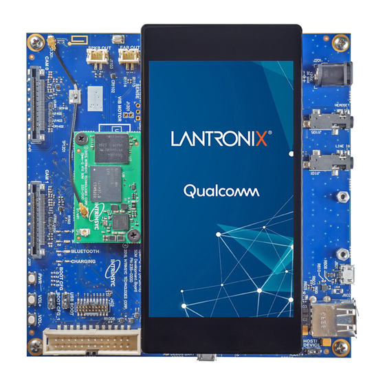
The Open-Q™ 410 Development Kit is shipped with the following (see figure below): • Open-Q™ 410 SOM with APQ8016E processor Android 5.0 (lollipop) pre-loaded • 13mm x 13mm Carrier Board • • AC power adapter Open-Q 410 Dev Kit User Guide... -
Page 10: Hardware Identification Labels
2: Overview Figure 1 – Assembled Open-Q 410 Development Kit There are also some optional accessories available for the Open-Q 410 Development Kit, such as: Open-Q™ 5MP (OmniVision OV5640) Camera Module (For Rev 0100) • Open-Q 13MP (Sony IMX214) Camera Module (For Rev 0200) •... - Page 11 2: Overview NOTE: Users should retain a copy of the SOM and Carrier Board label information for warranty and support purposes. Open-Q 410 Dev Kit User Guide...
-
Page 12: Block Diagram
Figure 2 – Open-Q™ 410 Development Kit Block Diagram (Rev 0100 shown here) 2.6 Feature List The table below lists the features of the Open-Q 410 Development Kit hardware. Table 1 – Open-Q 410 Development Kit Hardware Features Subsystem or... - Page 13 Audio output audio outputs Digital Mic Digital microphone input Power Button Power Button Volume Up Increase Volume Button Buttons Decrease Volume button/ Volume Down Reset Power presence indicator. Indicating LED Power ON Red LED Open-Q 410 Dev Kit User Guide...
- Page 14 1 x USB2.0 device Micro-B USB 2.0 Connector Dual Type-A USB 2.0 2 x USB2.0 host Connector Debug UART via USB Micro- Debug UART FTDI UART to USB Bridge B connector 1 x JTAG JTAG header Open-Q 410 Dev Kit User Guide...
-
Page 15: Custom Hardware Configurations
Reference documents R- 1 through R-3 describe how to design custom carrier boards and peripherals for specific applications. For information on how Lantronix can assist in the development of custom hardware and software designs, go to: http://helpdesk.intrinsyc.com... -
Page 16: Open-Q Tm 410 Som
410 (APQ8016E) SOM measures 26.5mm x 44mm. A top view of the SOM is shown below. Figure 3 – Top View of Open-Q 410 SOM The SOM connects to the Carrier Board with two 100-pin board to board connectors, as shown by the bottom side view below. -
Page 17: Figure 5 - Open-Q™ 410 (Apq8016E) Som Block Diagram
Figure 5 – Open-Q™ 410 (APQ8016E) SOM Block Diagram The Open-Q 410 Development Kit is provided with the SOM connected and secured to the Carrier Board. The sections below include more information for the development kit user. Open-Q 410 Dev Kit User Guide... -
Page 18: Carrier Board Connection
The SOM includes a U.FL coaxial connector on the top side, which provides the connection to the single band Wi-Fi / BT antenna feed from the WCN3620. The Open-Q 410 Development Kit is shipped with this antenna feed connected to a PCB trace antenna on the Carrier board with a U.FL coaxial cable. -
Page 19: Open-Q 410 Carrier Board
DIP Switch DIP Switch USB force boot 1. SDC1 (eMMC on SOM) Default configuration 2. SDC2 (µSDµ socket on Carrier) 3. USB2.0 1. SDC2 (µSDµSD socket Carrier) 2. SDC1 (eMMC on SOM) 3. USB2.0 Open-Q 410 Dev Kit User Guide... -
Page 20: Buttons And Leds
The main power input barrel connector (J201) is located on the top side of Carrier Board, as shown below. The main power input requires a 10-16VDC supply rated for at least 3A. Lantronix encourages using the 12VDC / 3A power supply provided with the kit. The main power input is protected by a very fast acting 5A rated fuse. -
Page 21: Debug Serial Uart Over Usb
+5V buck power supply operational. 2. See software release notes for the latest status of battery support in the 410 BSP. Otherwise, contact Lantronix for assistance in enabling battery operation in your BSP. Figure 8 – Battery Input Header The pinout for the J1202 battery header is shown in the table below. -
Page 22: Mipi Csi Camera Connectors
410 carrier board has two MIPI CSI camera connectors: J701 and J702. The two Samtec LSHM-120-02.5-L-DV-A-S-K-TR 40-pins connector are shown in the figure below. Figure 10 – MIPI CSI Camera Connectors on Rev 0100 CB Open-Q 410 Dev Kit User Guide... -
Page 23: Table 4 - Mipi Csi Camera Connector Pinout (For Rev 0100)
Output. Camera power down. GPIO34) GPIO33) 20, 22 CCI0_I2C_SCL / SDA CCI0_I2C_SCL / SDA Camera CCI0 I2C clock interface 34, 36 BLSP6_0 / 1 BLSP6_0 / 1 Spare I2C port. 14, 26, Not connected. 28, 30 Open-Q 410 Dev Kit User Guide... -
Page 24: Open-Qtm Carrier Board Rev 0200
Not Available (N/C) Input. MIPI CSI0 data lane 3 SI0_LA NE3_N/ This pair’s order is swapped on purpose CSI0_R CSI1_RST_N Output. Camera reset. ST_N (APQ8016E GPIO 28) (APQ80 GPIO CSI0_P CSI1_PWDN Output. Camera power down. Open-Q 410 Dev Kit User Guide... - Page 25 J1401 J1501 Description (APQ80 (APQ8016E GPIO 33) GPIO CCI0_I2 CCI0_I2C_SCL External PU to VREG_L6_1P8 through a 2K on Open-Q 410 CCB C_SCL (APQ8016E GPIO 30) (APQ80 GPIO CCI0_I2 CCI0_I2C_SDA External PU to VREG_L6_1P8 through a 2K on Open-Q 410 CCB...
-
Page 26: Display Connector
The Carrier board display connector (J801) provides the means for connecting the optional DSI display adapter assembly or the HDMI output adapter. The connector used is an FCI 60-pin 10106813-061112LF. Figure 12 – Display Connector J801 Open-Q 410 Dev Kit User Guide... - Page 27 4: Open-QTM 410 Carrier Board The table below describes the pin out for the display connector. Signal directions listed are relative to the carrier board. Unless noted otherwise, single ended signals are referenced to +1.8V. Open-Q 410 Dev Kit User Guide...
-
Page 28: Usb Host / Device Connections
USB micro-B connector (J601) to an external USB host. If J601 is connected, the USB port operates as device mode. If J601 is not connected, the USB port operates as host mode on J602. It is recommended to power down before switching the USB device / host capability. Open-Q 410 Dev Kit User Guide... -
Page 29: Micro Sd Socket
410 Platform has a Micro SD push-push style socket connected to the SDC2 interface of the processor. The socket is found on the bottom side of the board as shown below. Figure 14 – Micro SD Socket, J901 Open-Q 410 Dev Kit User Guide... -
Page 30: Sensor Expansion Header
Since this connector contains power rails, GPIOs, and I2C lines, it can be used for purposes other than a sensor interface, such as connecting the Lantronix IoT development kit. The table below describes the pin-out for the sensor expansion header. Signal directions listed are relative to the carrier board. Unless noted otherwise, single ended signals are referenced to +1.8V. -
Page 31: Table 7 - Sensor Expansion Header Pinout
BLSP50 BLSP52 Connected to APQ8016E GPIO19 APQ8016E BLSP5 bit (BLSP 5 bit 0). Can be used as I2C SCL. Connected to BLSP32 BLSP33 Connected to APQ8016E GPIO9 APQ8016E BLSP3 bit (BLSP 3 bit 2). Open-Q 410 Dev Kit User Guide... -
Page 32: Jtag Header
JTAG module presence is detected via pin Input. Connected to JTAG_TRST_N APQ8016E TRST_N pin. Input. Connected to JTAG_TDI APQ8016E TDI pin. Input. Connected to JTAG_TMS APQ8016E TMS pin. Input. Connected to JTAG_TCK APQ8016E TCK pin. Open-Q 410 Dev Kit User Guide... -
Page 33: Audio Connectors
There are two 3.5mm audio jacks on the carrier board as shown below. Connector J1105 is configured for use with a typical TRRS Android headset jack. Connector J1101 is wired for use as a stereo line input. Open-Q 410 Dev Kit User Guide... -
Page 34: Speaker Connectors
There are two, 2-pin speaker connectors on the carrier board as shown below. Connector J1102 is for the earpiece audio output. Connector J1103 is for the loud speaker output. Both connectors are of type JST B2B- PH-SM4-TB(LF)(SN). Figure 18 – Speaker Connectors Open-Q 410 Dev Kit User Guide... -
Page 35: Digital Mic Header
The header is found on the bottom side of the carrier board. Figure 19 – Digital Mic Header The pinout for the digital Mic header is shown below. Open-Q 410 Dev Kit User Guide... -
Page 36: Other Interfaces
1. Install R1209 (0Ω). (Pulling CBL_PWR_N to GND) 2. Set the device into device mode (Only required for Rev 0100) 3. Connect the development kit to a PC through J601 (ADB port, not serial debug) Open-Q 410 Dev Kit User Guide... -
Page 37: Output Display Options
5.1 On-Board Display There are two optional on-board displays supported by the Open-Q 410: 1. 4.46” FWVGA MIPI DSI LCD (Manufactured by Truly) with capacitive multi-touch 2. 4.5” FWVGA MIPI DSI LCD (Manufactured by OSD Displays) with capacitive multi-touch Option 1: 4.46”... -
Page 38: Hdmi Output Adapter
HDMI output adapter installed on the development kit. There is a standard HDMI 1.4 Type A connector on a top left corner of the carrier board after the HDMI output adapter installed. Figure 21 – HDMI Output Adapter Open-Q 410 Dev Kit User Guide...
Need help?
Do you have a question about the Open-Q 410 and is the answer not in the manual?
Questions and answers