Lantronix xPico User Manual
Hide thumbs
Also See for xPico:
- User manual (79 pages) ,
- Quick start manual (11 pages) ,
- Quick start manual (11 pages)
Table of Contents
Advertisement
Quick Links
Advertisement
Table of Contents

Related Manuals for Lantronix xPico


Summary of Contents for Lantronix xPico
- Page 1 Development Kit User Guide Part Number 900-643-R Revision A August 2012...
-
Page 2: Copyright And Trademark
Copyright and Trademark © 2012 Lantronix, Inc. All rights reserved. No part of the contents of this book may be transmitted or reproduced in any form or by any means without the written permission of Lantronix. Lantronix® is a registered trademark and xPico™ is a trademark of Lantronix, Inc. -
Page 3: Table Of Contents
Contents of the Kit_______________________________________________________ 6 Evaluation Board Description ______________________________________________ 6 Serial Port 1 and 2 RS232/RS485 Interfaces __________________________________ 9 Ethernet Port __________________________________________________________ 12 Power Supply _________________________________________________________ 12 LEDs ________________________________________________________________ 14 Additional Headers _____________________________________________________ 15 Evaluation Board Schematic ______________________________________________ 16 xPico Development Kit User Guide... -
Page 4: List Of Figures
List of Figures Figure 2-1 xPico Evaluation Drawing _______________________________________ 7 Figure 2-2 JP11 and JP12 Headers _______________________________________ 10 Figure 2-3 JP8, JP9, and JP10 Headers ___________________________________ 11 Figure 2-4 JP13 Header ________________________________________________ 12 Figure 2-5 Evaluation Board Schematic, Part 1 of 5 __________________________ 16... -
Page 5: Introduction
1. Introduction About this Guide This guide provides the information needed to use the xPico with the Development Kit. The intended audience is the engineers responsible for integrating the xPico into their product. Notes: Everything required to evaluate the CoBos OS-based turnkey application is provided in the development kit. -
Page 6: Development Kit
2. Development Kit Using an xPico sample and the xPico Development Kit, you can get familiar with the product and understand how to integrate the xPico into a given product design. Contents of the Kit The xPico Development Kit contains the following items: ♦... -
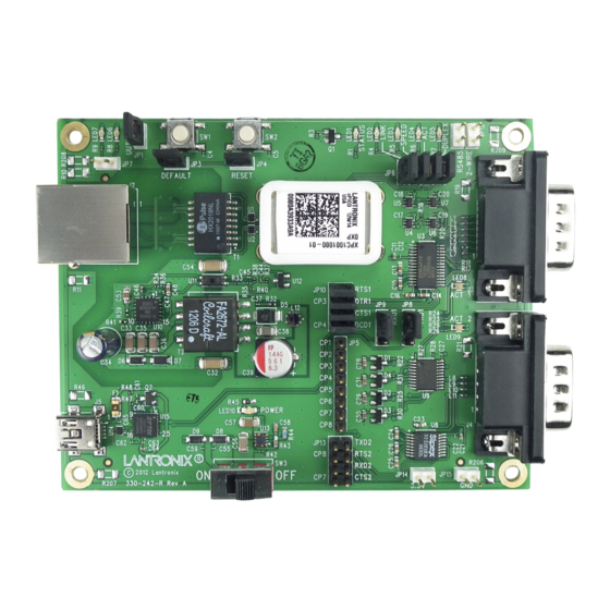
Page 7: Figure 2-1 Xpico Evaluation Drawing
Table 2-1 Evaluation Board Connectors, Header and Switches Ref Des. Connector/Header Function xPico Module Socket 40 pin socket for xPico module RJ45 Connector 10/100Mbps Ethernet connector. PoE powered device port. Serial Port 1 DB9 Standard RS232/RS422/RS485 DB9 serial port connector. - Page 8 Leave open for RS232 or 4-wire mode. Install for 2-wire mode. Serial Port 2 Breakout Header JP13 Install jumpers to connect xPico Serial Port 2 TX/RX and configurable pins to the RS232 transceiver for Serial Port 2. 3.3V Power Header JP14 Provides access to the internal 3.3V power rail.
-
Page 9: Serial Port 1 And 2 Rs232/Rs485 Interfaces
The evaluation board has one multiprotocol RS-232/RS422/RS485 port and one RS232 port for connection to the xPico internal UARTs. The ports are DB9 type connectors labeled J3 and J4. Included with the kit is a DB9-to-DB9 null modem cable (Lantronix P/N 500-164-R). -
Page 10: Table 2-5 Jp11 And Jp12 Jumper Settings For Serial Port 1 (J3)
JP13 serial port signal connections. Install jumper or remove as needed for desired function. In addition, the first serial port on the xPico module can be connected to either the DB9 serial port on J3 or to the USB on J5 via the on board USB-to-serial converter. Jumpers JP8 and JP9 allow for the selection of sending the J3 DB9 or J5 USB-to-Serial Port 1. -
Page 11: Table 2-6 Jp8 And Jp9 Port 1 Db9 Serial Or Usb/Serial Selection Headers
Serial port RTS1 or TX enable or configurable RS232 RTS, RS485 TX Enable Serial port CTS1 or configurable pin RS232 CTS Configurable pin CP3 or Serial port DTR1 RS232 DTR Configurable pin CP4 or Serial port DCD1 RS232 DCD xPico Development Kit User Guide... -
Page 12: Ethernet Port
Pin 1 Pin 2 Ethernet Port The xPico evaluation board includes one RJ45 with on-board magnetics for connection to the xPico module 10/100Mbps Ethernet interface. Connector J2 is the Ethernet port. Power Supply The evaluation board provides several options for input power. Included with the kit is a 5V wall adapter. -
Page 13: Table 2-9 Evaluation Board Power Options
Note: Host port can communicate with serial port via on-board USB-to- serial converter. See Table 2-1 for JP8 and JP9 jumper pin selection. Connect J2 Ethernet port to external PoE PSE switch or PoE injector xPico Development Kit User Guide... -
Page 14: Leds
2: Development Kit LEDs The xPico evaluation board includes several LEDs for signal and unit status. The table below lists all of the LEDs and their function. Table 2-10 LEDs Signals LED Ref Color LED Function Design xPico Status LED1 Orange LED blinks with patterns indicating module status. -
Page 15: Additional Headers
CP4, configurable pin Test point JP5 pin 5 CP5, configurable pin Test point JP5 pin 6 CP6, configurable pin Test point JP5 pin 7 CP7, configurable pin Test point JP5 pin 8 CP8, configurable pin Test point xPico Development Kit User Guide... -
Page 16: Evaluation Board Schematic
Evaluation Board Schematic Figure 2-5 Evaluation Board Schematic, Part 1 of 5 xPico Development Kit User Guide... - Page 17 2: Development Kit Figure 2-6 Evaluation Board Schematic, Part 2 of 5 xPico Development Kit User Guide...
- Page 18 2: Development Kit Figure 2-7 Evaluation Board Schematic, Part 3 of 5 xPico Development Kit User Guide...
- Page 19 2: Development Kit Figure 2-8 Evaluation Board Schematic, Part 4 of 5 xPico Development Kit User Guide...
- Page 20 2: Development Kit Figure 2-9 Evaluation Board Schematic, Part 5 of 5 xPico Development Kit User Guide...
Need help?
Do you have a question about the xPico and is the answer not in the manual?
Questions and answers