
Related Manuals for Lantronix Open-Q 845 mSOM


Summary of Contents for Lantronix Open-Q 845 mSOM
- Page 1 Open-Q™ 845 µSOM Development Kit User Guide Part Number PMD-00015 Revision A July 2020...
-
Page 2: Contacts
Phone: 949-453-3990 Fax: 949-453-3995 IES Customer Support Portal https://helpdesk.intrinsyc.com Lantronix Technical Support http://www.lantronix.com/support Sales Offices For a current list of our domestic and international sales offices, go to the Lantronix web site at http://www.lantronix.com/about-us/contact/ Open-Q 845 µSOM Development Kit User Guide... -
Page 3: Revision History
Intrinsyc document number: ITC-01DEV1430-UG-001 July 2020 Initial Lantronix document. Added Lantronix document part number, Lantronix logo, branding, contact information, and links. For the latest revision of this product document, please go to: http://tech.intrinsyc.com. Open-Q 845 µSOM Development Kit User Guide... -
Page 4: Table Of Contents
Table of Contents Contacts __________________________________________________________________ 2 Revision History ____________________________________________________________ 3 Table of Contents __________________________________________________________ 4 List of Figures _____________________________________________________________ 6 List of Tables ______________________________________________________________ 6 1 Introduction Purpose ____________________________________________________________ 7 Scope _____________________________________________________________ 7 Intended Audience ___________________________________________________ 7 2 Documents Applicable Documents_________________________________________________ 8 Reference Documents_________________________________________________ 8 Terms and Acronyms _________________________________________________ 8 3 Open-Q 845 µSOM Development Kit... - Page 5 3.7.8 Debug Serial UART over USB J1600 (12) _____________________________ 24 3.7.9 USB 3.1 Type C (for ADB) J2300 (11) ________________________________ 24 3.7.10 USB 3.1 Type A Connector J2400 (5) _______________________________ 24 3.7.11 Micro SD Card Socket J1500 (22) __________________________________ 25 3.7.12 Display Connector J1400 (38) _____________________________________ 26 3.7.13...
-
Page 6: List Of Figures
List of Figures Figure 1. Assembled Open-Q 845 µSOM Development Kit ............11 Figure 2. Open-Q 845 µSOM Dev Kit Block Diagram ..............14 Figure 3. DIP switch assignments ....................18 Figure 4. Input Power Selection Locations ..................19 Figure 5. SOM Current Sense Header J301 (5) ................21 Figure 6. -
Page 7: Introduction
Purpose The purpose of this user guide is to provide instructions and technical information on the Open-Q 845 µSOM Development Kit. You can find information on this and other Lantronix development kits on the Lantronix web site: http://www.lantronix.com/products Scope This document will cover the following items on the Open-Q 845 µSOM Development Kit: •... -
Page 8: Documents
2: Documents 2 Documents This section lists the supplementary documents for the Open-Q 845 µSOM Development Kit. Applicable Documents REFERENCE TITLE Intrinsyc Purchase and Software License Agreement for the Open-Q Development Reference Documents The below listed documents are available on the Technical Portal: https://tech.intrinsyc.com (dev kit registration required) - Page 9 2: Documents Global Positioning system HDMI High Definition Media Interface HSIC High Speed Inter Connect Bus JTAG Joint Test Action Group Low Noise Amplifier MIPI Mobile Industry processor interface Multi-Purpose Pin Near Field Communication Qualcomm Universal Peripheral (Serial interfaces like UART / SPI / I2C/ UIM) Radio Frequency SATA...
-
Page 10: Open-Q 845 Μsom Development Kit
3: Open-Q 845 µSOM Development Kit 3 Open-Q 845 µSOM Development Kit Introduction The Open-Q 845 provides a quick reference and evaluation platform for the Qualcomm Snapdragon SDA845 Platform. The development kit is suited for Android application developers, OEMs, consumer manufacturers, hardware component vendors, camera vendors, and product designers to evaluate, optimize, test and deploy applications that can utilize the Qualcomm Snapdragon SDA845 Platform technology. -
Page 11: Important Locations
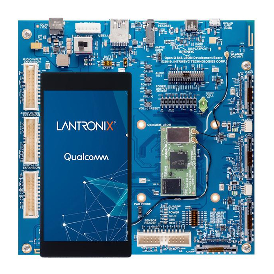
3: Open-Q 845 µSOM Development Kit o AC power adapter 3.4.1 Important Locations The diagram below shows the locations of key components, interfaces, and controls. Figure 1. Assembled Open-Q 845 µSOM Development Kit Open-Q 845 µSOM Development Kit User Guide... -
Page 12: Table 1. List Of Development Kit Features Itemized In The Figure Above
3: Open-Q 845 µSOM Development Kit Table 1. List of Development Kit Features itemized in the figure above Position Feature Description Reference Designator DC Power Supply Jack J400 Power Source Selector S300 Battery Input Header J300 Battery Configuration DIP Switch S301 USB 3.1 Type A Connector J2400... -
Page 13: Block Diagram
3: Open-Q 845 µSOM Development Kit Audio Codec Module (on top side of Carrier Board underneath U1700 Display Adapter) Power Header J700 Coin Cell Holder B300 Open-Q 845 µSOM, WLAN/BT CH0 Antenna Connector J2200 (on µSOM) Open-Q 845 µSOM, WLAN CH1 Antenna Connector J2201 (on µSOM) Open-Q 845 µSOM On-Board Quiet Thermistor... -
Page 14: Optional Accessories
Optional accessories are available for the Open-Q 845 µSOM Development Kit, like LCD Panel, Camera adapter, and sensor board. Please visit the product store for availability of these accessories: https://shop.intrinsyc.com/collections/accessories, or contact Lantronix Sales. Open-Q 845 µSOM Development Kit User Guide... -
Page 15: Getting Started
3: Open-Q 845 µSOM Development Kit Getting Started This section explains how to setup the Open-Q 845 µSOM Development Kit and start using it. 3.5.1 Registration To register the development kit and gain access to the Intrinsyc Technical Document Portal, please visit: http://tech.intrinsyc.com/account/register. -
Page 16: Open-Q 845 Μsom
SMD Button Volume +Key Volume – key SMD Button Volume – Key Sensor Connector 24 pin Sensor Expansion Connector Available via Lantronix optional accessories kit Digital IO Expansion Exposes general purpose IO for Header user development Audio Headset Jack Audio Headset Jack Audio Headset Open-Q 845 µSOM Development Kit User Guide... -
Page 17: Som Board To Board Connectors (33)
3: Open-Q 845 µSOM Development Kit Item Position Description Specification Usage Audio Inputs Audio Inputs Header 3 Analog Differential Inputs, Microphones Expansion 3 PDM Input Interfaces with phantom power Audio Outputs Audio Outputs Header 2 Line outputs, 1 earphone Amplifiers Expansion amplifier output, 1 Soundwire interface... -
Page 18: Figure 3. Dip Switch Assignments
Function Description Notes Switch For factory mode programming. Connected FORCED_USB_BOOT S2600-1 For Lantronix use only. Leave open / OFF. to CPU GPIO57. Enables WATCHDOG_DISABLE when DIP Unsupported feature. Leave switch open WATCHDOG _DISABLE S2600-2 switch turned on. Connected to CPU / OFF. -
Page 19: Input Power Selection
3: Open-Q 845 µSOM Development Kit 3.7.3 Input Power Selection The development kit can be powered using either external DC power supply or by using a battery. The input power source selection is performed by using the connectors and selection switches shown in the figure and subsections below. -
Page 20: Som Current Sense Header J301 (35)
3: Open-Q 845 µSOM Development Kit Function Description Notes Switch use of the ‘fake’ 10K thermistor on the carrier board. For battery powered dev kit, set switch to open / OFF if thermistor is included on the battery pack. Otherwise keep switch closed / ON. -
Page 21: Figure 5. Som Current Sense Header J301 (5)
3: Open-Q 845 µSOM Development Kit Figure 5. SOM Current Sense Header J301 (5) The table below summarizes the pin outs of header J301 Table 6 - Power Header J301 Pinout Pin No Signal Description SOM_PWR_SENSE_P SOM power positive current sense line SOM_PWR_SENSE_N SOM power negative current sense line System Ground... -
Page 22: Coin Cell Battery Holder B300 (30)
3: Open-Q 845 µSOM Development Kit 3.7.5 Coin Cell Battery Holder B300 (30) The coin cell holder allows the user to use a coin cell for supplying power to the SOM VCOIN power input. It is recommended that the Panasonic ML621 series rechargeable coin cell be used (not supplied with the development kit). -
Page 23: User Buttons And Leds (7, 36)
3: Open-Q 845 µSOM Development Kit Signal Description Signal Description +5.0V Carrier Board Boost Power Main +12.0V Power MB_VREG_5P0 DC_IN_12V Supply for general from DC power jack +5.0V rail. 3.7.7 User Buttons and LEDs (7, 36) There are four user buttons and four LED’s on the Open-Q 845 µSOM Development Kit as described in the tables below. -
Page 24: Debug Serial Uart Over Usb J1600 (12)
3: Open-Q 845 µSOM Development Kit Table 8. Development Kit Buttons (7) Reference User Button Function Designator S2500 Volume + Use this button to control or increase the volume. Use this button to control or decrease the volume. This button S2502 Volume -/Reset can also be used to reset the board. -
Page 25: Micro Sd Card Socket J1500 (22)
3: Open-Q 845 µSOM Development Kit to 1A VBUS current for external devices. See item 5 in Figure 1 for the location of J2400 on the carrier board. If the user intend to use a mini-PCIe card on the dev kit that requires a USB connection (see 3.7.15 below), then the Mini-PCIe USB enable DIP switch S2401 (6) must be switched to closed / ON (figure below). -
Page 26: Display Connector J1400 (38)
The 100-pin display connector, J1400, allows for an optional display adapter to be connected to the development kit. Lantronix offers a compatible LCD panel accessory for the Open-Q 845 µSOM Development Kit. It can be purchased by contacting Lantronix Sales. -
Page 27: Camera Connectors J1000 (15), J1100 (16), J1200 (17), J1300 (18)
J1200, and J1300 allowing users to connect multiple camera adapters to the development kit. See items 15 through 18 in Figure 1 for the carrier board locations of the camera connectors. Lantronix offers compatible camera module accessories for the Open-Q 845 µSOM Development Kit here: https://shop.intrinsyc.com/collections/accessories... -
Page 28: Camera Flash Connectors J1001 (19) And J1201 (20)
3: Open-Q 845 µSOM Development Kit 3.7.14 Camera Flash Connectors J1001 (19) and J1201 (20) In addition to the four camera connectors, the video capturing subsystem of the Open-Q 845 µSOM Development Kit is equipped with two connectors for flash or torch devices (J1001 and J1201). The PMI8998 power management IC has three flash channels, each with a maximum 1.5A rated regulated current sink. -
Page 29: Digital Io Expansion Header J2200 (23)
3: Open-Q 845 µSOM Development Kit Figure 10. Mini-PCIe and Optional SIM Card Sockets The Mini-PCIe card socket supports both the standard full and half size PCI Express mini cards with the 4 mounting holes located below J2800 in the image above. The pinout of J2800 complies with the PCI Express mini card standards. -
Page 30: Sensor Io Expansion Header J2100 (21)
3: Open-Q 845 µSOM Development Kit Table 11. Digital IO Expansion Header J2200 Pinout Signal Description Signal Description µSOM LDO Regulator µSOM LDO Regulator S4A VREG_S4A_1P8 VREG_S4A_1P8 S4A +1.8V +1.8V SSC8_QUP2_0_SPI2_ CPU Sensor Core Carrier board switching MB_VREG_3P3 MISO SSC_GPIO8 regulator. -
Page 31: Audio Inputs Expansion Header J1900 (27)
3: Open-Q 845 µSOM Development Kit µSOM low voltage µSOM LDO L19A VREG_LVS2A_1P8 VREG_L19A_3P0 switch LVS2 +1.8V +3.0V Ground Ground GPIO122_HRM_INT CPU GPIO122 GPIO125_TS_INT_N CPU GPIO125 CPU Sensor Core SSC6_QUP1_4_SPI1_CS1_N GPIO120_ALSP_INT_N CPU GPIO120 SSC_GPIO6 GPIO62_QUA_MI2S_DATA2 CPU GPIO62 GPIO119_MAG_INT_N CPU GPIO119 No Net GPIO124 CPU GPIO124... -
Page 32: Audio Outputs Expansion Header J1901 (26)
3: Open-Q 845 µSOM Development Kit 3.7.19 Audio Outputs Expansion Header J1901 (26) The Open-Q 845 µSOM Development Kit audio subsystem is built around the Qualcomm Audio Codec WCD9340 (28). The Audio Outputs Expansion Header J1901 exposes some of the audio output capabilities of WCD9340 for the user. - Page 33 3: Open-Q 845 µSOM Development Kit Signal Description Signal Description GPIO61_QU GPIO58_QUA_MI2 CPU GPIO58 – can be configured as CPU GPIO61 – can be configured A_MI2S_DAT S_SCK QUA_MI2S_SCK as QUA_MI2S_DATA1 GPIO62_QU GPIO59_QUA_MI2 CPU GPIO59 – can be configured as CPU GPIO62 – can be configured A_MI2S_DAT S_WS QUA_MI2S_WS...
-
Page 34: Audio Headset Jack J1800 (8)
3: Open-Q 845 µSOM Development Kit Signal Description Signal Description Voltage from DC Power Input DC_IN_12V No net +12.0V MB_VREG_1 Carrier board switching regulator Ground +1.8V 1. Population option changes are necessary in order to use this signal. See the carrier board schematic (R-3) for more details. -
Page 35: Table 16. Haptic Output Header Pinout J802
3: Open-Q 845 µSOM Development Kit Table 16. Haptic Output Header Pinout J802 Pin No Signal Description HAP_OUT_R_P Haptic output positive HAP_OUT_R_N Haptic output negative Open-Q 845 µSOM Development Kit User Guide...
Need help?
Do you have a question about the Open-Q 845 mSOM and is the answer not in the manual?
Questions and answers