
Related Manuals for Taylor C706


Summary of Contents for Taylor C706
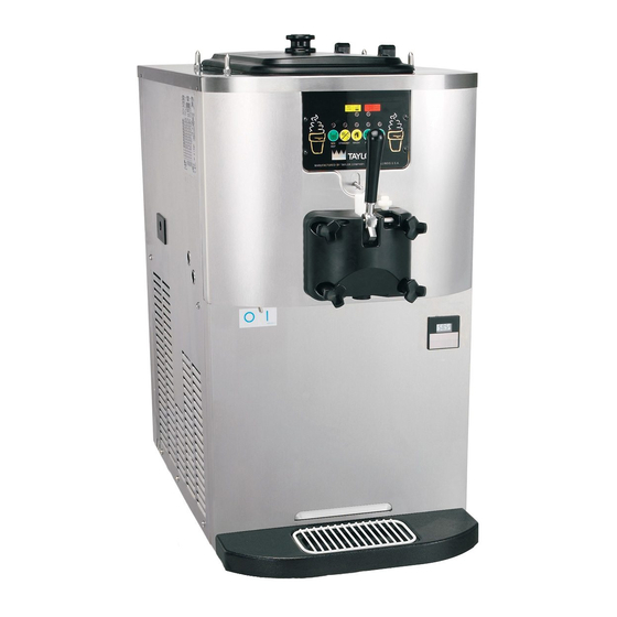
- Page 1 Model C706 Soft Serve Freezer Original Operating Instructions 056436- -M February, 2003 (Original Publication) (Updated May, 2011)
- Page 2 Minimum Wire Ampacity: E February, 2003 Taylor All rights reserved. 056436--M Taylor Company The word Taylor and the Crown design 750 N. Blackhawk Blvd. are registered trademarks in the United States Rockton, IL 61072 of America and certain other countries.
-
Page 3: Table Of Contents
............Model C706 Single Spout Door and Beater Assembly . - Page 4 E February, 2003 Taylor (Original Publication) (Updated May, 2011) All rights reserved. 056436--M Taylor Company The word Taylor and the Crown design 750 N. Blackhawk Blvd. are registered trademarks in the United States Rockton, IL 61072 of America and certain other countries.
-
Page 5: To The Installer
DO NOT obstruct air intake and discharge openings: Care should be taken to ensure that all basic safety The model C706 air cooled unit requires a minimum of practices are followed during the installation and 6” (152 mm) of clearance on both sides and 0” in the servicing activities related to the installation and rear of the unit. - Page 6 GFI, to protect FOLLOW YOUR LOCAL ELECTRICAL CODES! against the leakage of current, installed by the authorized personnel to the local codes. 101027 To the Installer Model C706...
- Page 7 If burns are severe, apply ice packs and contact a physician immediately. Note: The following procedures should be Taylor reminds technicians to be cautious of performed by a trained service technician. government laws regarding refrigerant recovery, recycling, and reclaiming systems.
-
Page 8: To The Operator
Distributor, and the required service work is provided by an authorized Taylor service technician. Taylor It should also be noted that Taylor does not warrant the reserves the right to deny warranty claims on refrigerant used in its equipment. For example, if the... -
Page 9: Safety
We at Taylor Company are concerned about the safety of the operator when he or she comes in contact with the freezer and its parts. Taylor has gone to extreme efforts to design and manufacture built--in safety DO NOT operate the freezer unless it is features to protect both you and the service technician. - Page 10 Protective gloves must be worn and the mounting holes must NOT be used to lift or hold the dispenser. Failure to follow this instruction can result in personal injury to fingers or equipment damage. 080908 Safety Model C706...
-
Page 11: Operator Parts Identification
066722-SP2 PAN A.-DRIP 5-1/2” LONG X56074 STUD-NOSE CONE 055987 PUMP A.-MIX SIMPLIFIED S.S. X57029-14 SHIELD-SPLASH 049203 PANEL A.-SIDE RIGHT (TOP X65441-SER AIR DISCHARGE UNITS, ONLY) TRAY-DRIP 056858 GUARD-FAN 028534-1 PANEL-FRONT-LOWER 058942 PANEL A.-FRONT-UPPER X58950 110509 Model C706 Operator Parts Identification... -
Page 12: Model C706 Single Spout Door And Beater Assembly
Model C706 Single Spout Door and Beater Assembly ITEM DESCRIPTION PART NO. ITEM DESCRIPTION PART NO. DOOR A.--W/BAFFLE X56071--SER NUT--STUD BLACK--3.25 LONG 058765 NUT--STUD BLACK--2.56 LONG 058764 HANDLE A.-DRAW-WELDED X56246 GASKET--DOOR HT 4” DBL 048926 SCREW-ADJUSTMENT-5/16-24 056332 KIT A.--BEATER FRONT SHOE X50350 O-RING-1/4 OD X .070W 50... -
Page 13: X57029--Xx Pump A. -- Mix Simplified
CAP-VALVE 056874-12 TUBE A.-FEED HOPPER X56521 SOFT SERVE GASKET - SIMPLIFIED PUMP 053527 VALVE RING-CHECK .120 OD 056524 ADAPTOR - MIX INLET 054825 CLIP-MIX PUMP RETAINER 044641 O-RING - 11/16 OD - RED 016132 050617 Model C706 Operator Parts Identification... -
Page 14: Accessories
*Item 6: A sample of Stera Sheen is shipped with new BRUSH-MIX·PUMP·BODY-3”X7 023316 equipment. To order additional sanitizer, use one of the SANITIZER STERA SHEEN 010425-CS part numbers listed. (JAR) SANITIZER STERA SHEEN 055492 (100/2 OZ. PACKETS) 110509 Operator Parts Identification Model C706... -
Page 15: Important: To The Operator
RESET BUTTON -- BEATER MOTOR MIX REFRIGERATION KEY RESET BUTTON -- PUMP STANDBY KEY POWER SWITCH (TOGGLE) WASH KEY HOPPER TEMP. INDICATOR AUTO KEY OPTIONAL FLAVOR BURST JACK *MAY NOT BE AVAILABLE ON ALL UNITS. 041118 Model C706 Important: To the Operator... -
Page 16: Symbol Definitions
To better communicate in the International arena, symbols have replaced words on many of our operator switches, function, and fault indicators. Your Taylor When the MIX REF key is pressed, the light comes on equipment is designed with these International indicating the mix hopper refrigeration system is symbols. -
Page 17: Wash Key
Adjustable Draw Handle Pump Key When the PUMP key is pressed, the light comes on, The Model C706 features an adjustable draw handle indicating the air/mix pump will operate as required. to provide the best portion control. The draw handle should be adjusted to provide a flow rate of 5 to 7--1/2 oz. -
Page 18: Feed Tube (Back--Up Option)
TUBE A.--FEED--SS 5/32 HOLE X29429--2 amount of air into the freezing cylinder. The air O--RING--.643 OD X .077 W 018572 orifice maintains overrun and allows enough mix to enter the freezing cylinder after a draw. 050126 Important: To the Operator Model C706... -
Page 19: Operating Procedures
Section 6 Operating Procedures Assembly The C706 unit stores mix in a hopper. The mix is pumped into the freezing cylinder. It has a 3.4 quart (3.2 liter) capacity freezing cylinder and a 20 quart (18.9 liter) mix hopper. We begin our instructions at the point where we enter... - Page 20 Do not lubricate the gasket or the front bearing. Figure 8 Figure 10 041118 Operating Procedures Model C706...
- Page 21 Slide the two o--rings into the grooves on the prime Step 5 plug. Apply an even coat of Taylor Lube to the o--rings Insert the draw valve from the top until the draw valve is at the bottom. and shaft.
-
Page 22: Mix Hopper Assembly
The o--rings and gasket cannot properly serve their intended function if nicks, cuts, or holes in the material are present. Replace any defective parts immediately and discard the old. Figure 20 041118 Operating Procedures Model C706... - Page 23 The drive hole in the mix inlet adaptor must be visible through the drive hole opening in the pump cylinder and the aligning notch located at the base of the adapter must be positioned into the notch at the Figure 22 bottom of the pump cylinder. Model C706 Operating Procedures...
- Page 24 Lay the pump assembly, pump clip, mix feed tube, and Step 10 cotter pin in the bottom of the mix hopper for sanitizing. Assemble the feed tube assembly. Slide the valve o--ring into the groove of the feed tube. Figure 26 Figure 28 030206 Operating Procedures Model C706...
-
Page 25: Sanitizing
Note: For ease in installing the pump, position the ball pump, the pump clip, the mix feed tube, and the locking crank of the drive shaft in the 3 o’clock position. clip. 080714 Model C706 Operating Procedures... - Page 26 Step 7 Figure 32 With an empty pail beneath the door spout, raise the Step 5 prime plug and press the PUMP key. Place the power switch in the ON position. Figure 33 Figure 35 041118 Operating Procedures Model C706...
-
Page 27: Priming
When full strength mix is flowing from the door spout, raise the draw handle. Figure 37 Note: Be sure your hands are clean and sanitized Note: Use only FRESH mix when priming the before continuing these instructions. freezer. 050126 Model C706 Operating Procedures... -
Page 28: Closing Procedure
Place the mix hopper cover in position. Closing Procedure To disassemble your unit, the following items will be needed: Two cleaning pails Sanitized stainless steel rerun can with lid Necessary brushes (provided with freezer) Cleaner Figure 40 Single service towels 041118 Operating Procedures Model C706... -
Page 29: Draining Product From The Freezing Cylinder
Once the cleaning solution stops flowing from the door flowing from the door spout, raise the draw handle and spout, raise the draw handle and press the WASH key, press the WASH key cancelling the WASH mode. cancelling the WASH mode. 080828 Model C706 Operating Procedures... -
Page 30: Disassembly
Place all the other hand, push the top of the o--ring forward and cleaned parts on a clean, dry surface to air dry it will roll out of the groove and can be easily removed. overnight. 080714 Operating Procedures Model C706... - Page 31 ITEM DESCRIPTION ITEM DESCRIPTION WHITE BRISTLE -- 1/2” x 1/2” WHITE BRISTLE -- 1/2” x 1” WHITE BRISTLE -- 3/16” x 1” WHITE BRISTLE -- 3” x 1/2” BLACK BRISTLE -- 1/4” x 1--1/4” 030102 Model C706 Operating Procedures...
-
Page 32: Section 7 Important: Operator Checklist
When using rerun, skim off the foam and discard. Mix the rerun with fresh mix in a ratio of j 5. Follow all lubricating procedures as outlined in 50/50 during the days operation. “Assembly”. 071205 Important: Operator Checklist Model C706... -
Page 33: The Air/Mix Pump Checklist
7. If your machine is equipped with an auxiliary Your local Taylor Distributor can perform this winter refrigeration system, check the auxiliary storage service for you. condenser for accumulation of dirt and lint. Dirty... -
Page 34: Section 8 Troubleshooting Guide
Locate cause of water loss and correct. 4. The mix in the mix hopper a. The temperature is out of a. Call service technician to ------ adjust the mix hopper is too cold. adjustment. temperature. Troubleshooting Guide Model C706... - Page 35 Inadequate lubrication of b. Lubricate properly. draw valve o--rings. c. Wrong type of lubricant is c. Use the proper lubricant (example: Taylor Lube). being used (example: petroleum base lubricant). 10. No freezer operation after a. Unit is unplugged. a. Plug into wall receptacle.
- Page 36 Inspect the o--rings. b. O--rings must not be worn, torn, or fit too loosely. c. Check the pump cylinder. c. The piston must be assembled correctly and fit snugly in the pump cylinder. Troubleshooting Guide Model C706...
- Page 37 18. Too much pressure in the a. Plugged relief hole in the a. Clean. ------ freezing cylinder. inlet tube. 19. Not enough pressure in a. Malfunctioning draw a. Contact service ------ technician. the freezing cylinder. switch. 030206 Model C706 Troubleshooting Guide...
-
Page 38: Section 9 Parts Replacement Schedule
White Bristle Brush, 1/2” x 1/2” Inspect & Replace Minimum if Necessary White Bristle Brush, 3/16” x 1” Inspect & Replace Minimum if Necessary White Bristle Brush, 3” x 1/2” Inspect & Replace Minimum if Necessary Parts Replacement Schedule Model C706... -
Page 39: Section 10 Parts List
Section 10 Parts List + Available Separately 110118 Model C706 Parts List... - Page 40 + Available Separately Parts List Model C706...
- Page 41 + Available Separately Model C706 Parts List...
- Page 42 + Available Separately Parts List Model C706...
- Page 43 + Available Separately 110315 Model C706 Parts List...
- Page 44 + Available Separately Parts List Model C706...
- Page 45 + Available Separately Model C706 Parts List...
- Page 46 + Available Separately Parts List Model C706...
- Page 47 Model C706 064288- -27 Rev. 5/11...
Need help?
Do you have a question about the C706 and is the answer not in the manual?
Questions and answers