
Related Manuals for Taylor C722


Summary of Contents for Taylor C722
- Page 1 OPERATOR'S MANUAL Model C722 Soft Serve Freezer Original Operating Instructions 080568-M 2/22/12 (Original Publication) Updated 11/21/13...
- Page 2 Complete this page for quick reference when service is required: Taylor Distributor: Address: Phone: Service: Parts: Date of Installation: Information found on the data label: Model Number: Serial Number: Electrical Specs: Voltage Cycle Phase Maximum Fuse Size: Minimum Wire Ampacity: E 2012 Carrier Commercial Refrigeration, Inc.
-
Page 3: Table Of Contents
....... Model C722 ............ - Page 4 Statutory Damages of up to $250,000 (17 USC 504) for infringement, and may result in further civil and criminal penalties. All rights reserved. Taylor Company a division of Carrier Commercial Refrigeration, Inc. 750 N. Blackhawk Blvd. Rockton, IL 61072 Model C722 Table of Contents...
-
Page 5: To The Installer
Authorized service personnel should consult The Model C722 air cooled unit requires a minimum of 6” (152 mm) on the left and right sides and 0” on OSHA Standard 29CFRI910.147 or the applicable code of the local area for the the back. -
Page 6: Water Connections (Water Cooled Units Only)
Check the data label(s) on the Uncrate the unit and inspect it for damage. Report freezer for branch circuit overcurrent protection or any damage to your Taylor Distributor. fuse, circuit ampacity, and other electrical specifications. Refer to the wiring diagram provided... -
Page 7: Beater Rotation
Optional Carts Taylor reminds technicians to be cautious of government laws regarding refrigerant recovery, There are two optional carts available. recycling, and reclaiming systems. If you have any... -
Page 8: To The Operator
The unauthorized use of alternate refrigerants will void your Taylor compressor warranty. It is the Note: Your Taylor warranty is valid only if the parts unit owner's responsibility to make this fact known to are authorized Taylor parts, purchased from the any technician he employs. -
Page 9: Safety
We, at Taylor Company, are concerned about the safety of the operator when he or she comes in contact with the freezer and its parts. Taylor has gone to extreme efforts to design and manufacture DO NOT operate the freezer unless it is built-in safety features to protect both you and the properly grounded. - Page 10 DO NOT obstruct air intake and discharge openings: cause severe injuries. The Model C722 air cooled unit requires a minimum of 6” (152 mm) on the left and right sides and 0” on DO NOT put objects or fingers in the door spout.
- Page 11 Notes: Model C722 Safety...
-
Page 12: Operator Parts Identification
Section 4 Operator Parts Identification Model C722 Figure 1 130506 Operator Parts Identification Model C722... - Page 13 Model C722 Exploded View Parts Identification ITEM DESCRIPTION PART NO. ITEM DESCRIPTION PART NO. COVER-HOPPER-14 QT BLACK 041682-BLA TRAY-DRIP 080781 ORIFICE 022465-100 SHIELD-SPLASH-WIRE 046177-SP O-RING-11/16ODX.103W-RED 016132 PAN A.-DRIP 15 1/8 LONG X51601 TUBE A.-FEED-SS-5/32 HOLE X29429-2 STUD-NOSE CONE 055987 O-RING-.643 OD X .077W...
-
Page 14: Door And Beater Assembly
O-RING-1/4 OD X .070W 015872 BLADE-SCRAPER-PLASTIC 080292 HANDLE A.-DRAW X56421-1 BEATER A.-2.8QT-1 PIN X80291 NUT-STUD-BLACK 3.250 LONG 058765 SHAFT-BEATER 081707 PLUG-PRIME TWIN 059936 SEAL-DRIVE SHAFT 032560 O-RING-1/2OD X .070W 024278 *NOT AVAILABLE SEPARATELY. ORDER X50350 KIT. 130319 Operator Parts Identification Model C722... -
Page 15: X69928-14S Pump A. - Mix Simplified S.s
PART NO. ITEM DESCRIPTION PART NO. ADAPTOR A.-MIX INLET-SS X80250 PIN-RETAINING X55450 GASKET-SIMPLIFIED PUMP 053527 CYLINDER-PUMP HOPPER 069920 CAP-VALVE BODY SS 056874-14 TUBE A.-FEED-LEFT X69919 O-RING-2-1/8 OD X .139W-#225 020051 TUBE A.-FEED-RIGHT X69924 PISTON-PUMP-SIMPLIFIED 069922 120905 Model C722 Operator Parts Identification... -
Page 16: Accessories
*A sample container of sanitizer is sent with the unit. For PAIL-MIX 10 QT 013163 reorders, order Stera Sheen part no. 055492 (100 2 oz. packs) or Kay-5 part no. 041082 (200 packs). **Not Shown. 130506 Operator Parts Identification Model C722... -
Page 17: Brushes
Brushes Figure 5 ITEM DESCRIPTION PART NO. ITEM DESCRIPTION PART NO. BLACK BRISTLE BRUSH 013071 WHITE BRISTLE BRUSH 023316 (3” x 7”) DOUBLE END BRUSH 013072 WHITE BRISTLE BRUSH 013073 (1” x 2”) Model C722 Operator Parts Identification... -
Page 18: Optional Carts
CASTER-3" SWV 3/4-10 STEM 021279 NOTE: ADA COMPLIANT HEIGHT CART, NOT PANEL-SIDE-STD CART 069428 EQUIPPED WITH A DOOR. CASTER-3" SWV 3/4-10 STEM 021279 PANEL-REAR-STD CART 069429 NOTE: STANDARD HEIGHT CART WITH REVERSIBLE FRONT DOOR PANEL AND REAR PANEL. Operator Parts Identification Model C722... -
Page 19: Important: To The Operator
Section 5 Important: To the Operator Model C722 Figure 7 ITEM DESCRIPTION POWER SWITCH LIQUID CRYSTAL DISPLAY KEYPADS MIX OUT INDICATORS STANDBY INDICATORS MIX LOW INDICATORS SELECT KEY SERVICE MENU KEY BRUSH CLEAN COUNTER ARROW KEYS TOPPING HEATER KEYS (NOT FUNCTIONAL) -
Page 20: Symbol Definitions
To better communicate in the International arena, symbols have replaced words on many of our operator switches, function, and fault indicators. = TOPPING HEATER-LEFT Your Taylor equipment is designed with these International symbols. = TOPPING HEATER-RIGHT The following chart identifies the symbol definitions. - Page 21 To cancel any function, touch the key again. The light and the mode of operation will shut off. Topping Heater Symbols The TOPPING HEATER symbols are not functional on the Model C722. Figure 8 Model C722 Important: To the Operator...
-
Page 22: Operating Screen Descriptions
ANY KEY ABORTS display the number of hours since the freezer was last brush cleaned. After hour 99, it will change to a letter and a number (example: A0, A1, ... B0, B1, Figure 9 etc.). Important: To the Operator Model C722... -
Page 23: Manager's Menu
Note: The machine will continue operation in the mode it was in when the menu was selected. However, the control keys will not be lit and are non-functional when the Manager's Menu is displayed. Figure 14 Model C722 Important: To the Operator... - Page 24 UP arrow symbol to move the arrow (>) to YES > Exit and touch the SEL symbol. The servings counter will reset to zero and exit back to the Manager's Menu. (See Figure 16.) Figure 19 Important: To the Operator Model C722...
- Page 25 (See Figure 26.) (See Figure 23.) AUTO START TIME DST START WEEK DISABLED > Second Sunday Enable Third Sunday > Disable Fourth Sunday Figure 23 Figure 26 Model C722 Important: To the Operator...
- Page 26 Pressing the SEL symbol any time faults are > Exit displayed will clear corrected faults upon returning to the Manager's Menu. Press the Menu symbol to Figure 29 return to the Manager's Menu. Important: To the Operator Model C722...
- Page 27 Press the SEL key to return to the Manager's Menu. failure. Note: Refer to your local health codes regarding Note: If no fault was found, the message will state, temperature recommendations for procedures to “NO FAULT FOUND”. follow if these fault screens appear. Model C722 Important: To the Operator...
- Page 28 Press the SEL or MENU symbols to machine. (See Figure 34.) return to the Manager's Menu. (See Figure 37.) SOFTWARE VERSION VISC C722 CONTROL UVC4 HOPPER 41.0 41.0 VERSION V00.00.000 BARREL 41.0 41.0...
-
Page 29: Operating Procedures
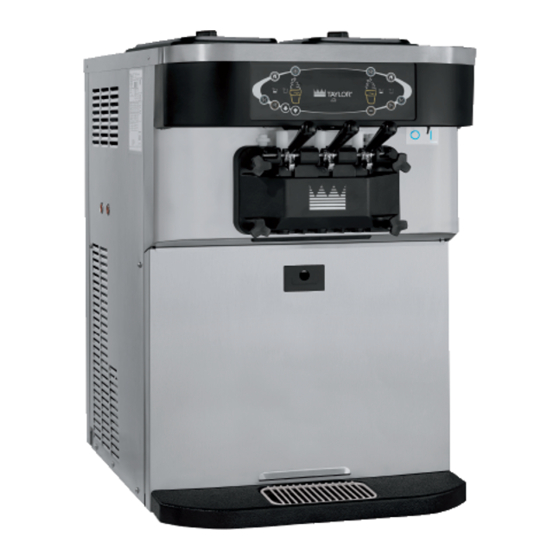
Section 6 Operating Procedures The Model C722 is a medium capacity soft serve Step 3 machine. Mix is stored in the hoppers. The unit is Heavily lubricate the inside portion of the boot seal. equipped with a three spout door and two 2.8 quart Also lubricate the flat end of the boot seal that (2.7 liter) capacity freezing cylinders. - Page 30 If the blades are in good condition, install the Install the beater shoes. (See Figure 44.) scraper blade clips over the scraper blades. Place the rear scraper blade over the rear holding pin on the beater. (See Figure 42.) Figure 42 Figure 44 130425 Operating Procedures Model C722...
- Page 31 (See Figure 45.) Slide the two o-rings into the grooves on each prime plug. Apply an even coat of Taylor Lube to the o-rings and shafts. Figure 45 Repeat these steps for the other side of the machine.
- Page 32 Slide the fork of each draw handle into the slot of each draw valve, starting from the right. Figure 50 Step 15 Lubricate the inside of the freezer door spouts, top and bottom. Figure 53 Operating Procedures Model C722...
- Page 33 To INCREASE the flow rate, tighten the screw. To DECREASE the flow rate, loosen the screw. Figure 57 Step 21 Install the front drip tray and splash shield under the door spouts. Figure 55 Figure 58 130425 Model C722 Operating Procedures...
-
Page 34: Mix Pump Assembly
(See Step 6 Figure 60.) Slide the pump valve gasket into the holes on the cap. DO NOT lubricate the gasket. (See Figure 63.) Figure 60 Figure 63 Operating Procedures Model C722... - Page 35 Insert the mix inlet assembly into the pump cylinder. (See Figure 65.) Step 10 Assemble the feed tube assembly. Slide the check ring into the groove of the feed tube. (See Figure 67.) Figure 65 Figure 67 120507 Model C722 Operating Procedures...
-
Page 36: Sanitizing
(See Figure 71.) Figure 71 Note: You have just sanitized the mix hopper and parts; therefore, be sure your hands are clean and Figure 69 sanitized before proceeding with these instructions. Operating Procedures Model C722... - Page 37 Failure to follow this instruction could result in sanitizer Step 14 spraying on the operator. (See Figure 73.) Place the agitator on the agitator drive shaft housing. Figure 73 Figure 74 120507 Model C722 Operating Procedures...
-
Page 38: Priming
Manual Brush Cleaning This Procedure Must Be Completed Every Day ALWAYS FOLLOW LOCAL HEALTH CODES. To disassemble the Model C722, the following items will be needed: Two cleaning and sanitizing pails Sanitizer/Cleaner Necessary brushes (provided with freezer) -
Page 39: Draining Product From The Freezing Cylinder
Wait at least 5 minutes before proceeding with these instructions. Step 5 Figure 77 Place an empty pail beneath the door spouts. Model C722 Operating Procedures... -
Page 40: Disassembly
Remove the o-rings from the draw seal(s) or o-ring(s) should be replaced or properly valves. lubricated. Operating Procedures Model C722... -
Page 41: Brush Cleaning
Using the black brush, clean the sanitized towel. rear shell bearing at the back of each freezing cylinder. (See Figure 80.) Note: The brush clean counter will reset to zero at this time. Figure 80 Model C722 Operating Procedures... -
Page 42: Important: Operator Checklist
Deteriorated or cracked water lines should be j 6. The temperature of mix in the mix hopper and replaced only by an authorized Taylor walk-in cooler should be below 40_F (4.4_C). distributor. Important: Operator Checklist... -
Page 43: Winter Storage
Winter Storage If the place of business is to be closed during the Your local Taylor Distributor can perform this winter winter months, it is important to protect the freezer storage service for you. by following certain precautions, particularly if the Wrap detachable parts of the freezer such as building is subject to freezing conditions. -
Page 44: Troubleshooting Guide
Machine is unplugged. a. Plug into wall receptacle. - - - (power switch is ON). b. Circuit breaker OFF or b. Turn the breaker ON or - - - replace the fuse. blown fuse. 121004 Important: Operator Checklist Model C722... - Page 45 9. Product is collecting on a. The top o-ring on draw a. Lubricate properly or replace the o-ring. top of the freezer door. valve is improperly lubricated or is worn. 121004 Model C722 Important: Operator Checklist...
- Page 46 Broken beater pins. c. Replace beater assembly. d. Beater assembly is bent. d. Replace beater assembly. - - - e. Gear box is out of e. Call an authorized service - - - technician. alignment. Important: Operator Checklist Model C722...
- Page 47 213 g.) of product by drawn. weight in 10 seconds. b. Pump assembled b. Assemble and lubricate according to instructions incorrectly. in this manual. c. Freezing cylinder not c. Drain the freezing cylinder and reprime the machine. primed correctly. Model C722 Important: Operator Checklist...
-
Page 48: Parts Replacement Schedule
Minimum if Necessary White Bristle Brush, 1” x 2” Inspect & Replace Minimum if Necessary Black Bristle Brush, 1” x 2” Inspect & Replace Minimum if Necessary Double-Ended Brush Inspect & Replace Minimum if Necessary Parts Replacement Schedule Model C722... -
Page 49: Section 10 Limited Warranty On Equipment
Taylor, through an authorized Taylor distributor or service agency, will provide a new or re-manufactured part, at Taylor’s option, to replace the failed defective part at no charge for the part. Except as otherwise stated herein, these are Taylor’s exclusive obligations under this limited warranty for a Product failure. - Page 50 LEGAL REMEDIES The owner must notify Taylor in writing, by certified or registered letter to the following address, of any defect or complaint with the Product, stating the defect or complaint and a specific request for repair, replacement, or other correction of the Product under warranty, mailed at least thirty (30) days before pursuing any legal rights or remedies.
-
Page 51: Limited Warranty On Parts
Taylor warrants the Parts against failure due to defect in materials or workmanship under normal use and service as follows. All warranty periods begin on the date of original installation of the Part in the Taylor unit. If a Part fails due to defect during the applicable warranty period, Taylor, through an authorized Taylor distributor or service agency, will provide a new or re-manufactured Part, at Taylor’s option, to replace the failed defective Part at no... - Page 52 Parts or the units in which they are installed repaired or altered in any way so as, in the judgment of Taylor, to adversely affect performance, or normal wear or deterioration.
-
Page 53: Taylor Company
LEGAL REMEDIES The owner must notify Taylor in writing, by certified or registered letter to the following address, of any defect or complaint with the Part, stating the defect or complaint and a specific request for repair, replacement, or other correction of the Part under warranty, mailed at least thirty (30) days before pursuing any legal rights or remedies. -
Page 54: Section 12 Parts List
Section 12 Parts List 121210 Parts List Model C722... - Page 55 Model C722 Parts List...
- Page 56 Parts List Model C722...
- Page 57 Model C722 Parts List...
- Page 58 Parts List Model C722...
- Page 59 Model C722 Parts List...
- Page 60 Parts List Model C722...
- Page 61 Model C722 Parts List...
- Page 62 130319 Parts List Model C722...
- Page 63 Model C722 Parts List...
- Page 64 Parts List Model C722...
- Page 65 Model C722 Parts List...
- Page 66 Model C722 080525-27 6/3/13...
- Page 67 Model C722 080525-40 6/3/13...
Need help?
Do you have a question about the C722 and is the answer not in the manual?
Questions and answers