Table of Contents
Advertisement
Advertisement
Table of Contents

Related Manuals for GARDASOFT TR-HT2 Series


Summary of Contents for GARDASOFT TR-HT2 Series
- Page 1 TR-HT2xx LED Controller Issue 005 User manual www.gardasoft.com...
- Page 2 Deliberate acts of endangerment and vandalism are not covered by this document and must be considered by the installer. While care has been taken in the preparation of this document Gardasoft Vision Ltd will not accept any liability for consequential loss of any kind except those required by law.
-
Page 3: Table Of Contents
TR-HT2xx LED Controller - User Manual Contents Getting started TR-HT features - a summary GigE VisionTM Safety Heat Electrical General Installation guidance (disclaimer) Sicherheit Wärme Elektrik Allgemein Installationsanleitung (Haftungsausschluss) Sécurité Chaleur Électricité Général Guide d'installation (clause de non-responsabilité) Mounting the TR-HT Environmental considerations Electrostatic discharge Connecting the TR-HT... - Page 4 TR-HT2xx LED Controller - User Manual Flags 8.3.1 Ethernet message flag (E) 8.3.2 FIFO flag (F) 8.3.3 Resync flag (R) 8.3.4 Pulse flag (P) Virtual outputs Trigger timing examples Synchronised camera and lighting Sequenced pulses Gated pulses Belt position triggering Multiple exposures with different lighting Simple FIFO mode Resync mode Resync and FIFO mode...
- Page 5 TR-HT2xx LED Controller - User Manual 13.2.3 Pulse mode 13.2.4 Trigger timing 13.2.5 Event codes 13.2.6 Error codes Appendix A - Configuration sheet...
- Page 6 TR-HT2xx LED Controller - User Manual — —...
-
Page 7: Getting Started
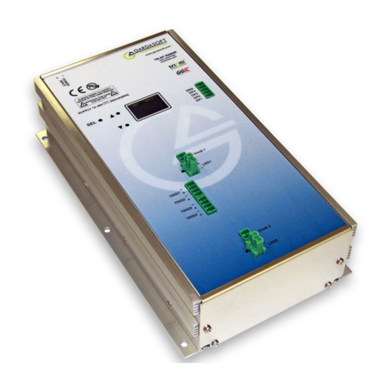
Section 11, Webpage configuration Section 12, Configuration commands. We recommend that you visit www.gardasoft.com for application notes on this product. There is also a support web page there, which has information on trouble-shooting problems. TR-HT features - a summary The TR-HT product is a dual channel LED lighting controller for use in machine vision applications that can deliver 50A per channel in pulse mode. -
Page 8: Safety
TR-HT2xx LED Controller - User Manual Safety Read this before using the TR-HT. Always observe the following safety precautions. If in doubt, contact your distributor or Gardasoft Vision. The following symbols mean: Warning: Read instructions to understand possible hazard Warning: Surface may get hot. -
Page 9: General
This information is for guidance only. Installers must perform their own risk assessment specific to each installation. While Gardasoft Vision Ltd has taken every care in the preparation of this advice, Gardasoft Vision Ltd accepts no liability for damages of any kind except those required by law. -
Page 10: Sicherheit
Sicherheit Bitte lesen Sie vor Verwendung des TR-HT diese Informationen. Beachten Sie immer die folgenden Sicherheitshinweise. Wenden Sie sich im Zweifelsfall an Ihren Händler oder Gardasoft Vision. Die folgenden Symbole haben die folgende Bedeutung: Warnung: Lesen Sie die Hinweise, um eine mögliche Gefahr zu verstehen. - Page 11 TR-HT2xx LED Controller - User Manual anderen Geräte, die an die Trigger- oder andere Ports angeschlossen sind, müssen ebenfalls durch eine doppelte Isolierung/verstärkte Isolierung vom Stromnetz getrennt sein. Das Netzgerät, das zur Stromversorgung des TR-HT dient, muss durch eine doppelte Isolierung/verstärkte Isolierung von der Stromversorgung getrennt sein und gegen Kurzschlüsse und Überlastungen geschützt sein.
-
Page 12: Allgemein
Risikobewertung für die jeweilige Installation durchführen. Auch wenn Gardasoft Vision Ltd diese Empfehlung mit größter Sorgfalt erstellt hat, übernimmt Gardasoft Vision Ltd keine Haftung für Schäden jeglicher Art, außer in dem gesetzlich erforderlichen Maße. Vorsätzliche Gefährdungs- oder Zerstörungshandlungen werden in diesem Dokument nicht behandelt und... -
Page 13: Sécurité
Sécurité Lisez ce document avant d'utiliser le TR-HT. Respectez les mesures de sécurité suivantes en toutes circonstances. En cas de doute, contactez votre distributeur ou Gardasoft Vision. Les symboles ci-dessous auront la signification suivante: Attention: Lisez les instructions pour comprendre quels sont les risques éventuels... - Page 14 TR-HT2xx LED Controller - User Manual surcharges. Nous recommandons d'utiliser un boîtier d'alimentation qui limite le courant de sortie de l'appareil à la valeur nominale appropriée du contrôleur, en réglant la limite de courant sur l'alimentation (si possible) ou via la protection contre les surcharges. Le boîtier d'alimentation doit être approuvé...
-
Page 15: Général
Ces informations sont seulement à titre indicatif. Les installateurs doivent effectuer leur propre évaluation des risques, pour chaque installation. Même si Gardasoft Vision Ltd a préparé minutieusement ces conseils, Gardasoft Vision Ltd décline toute responsabilité pour tout dommage, quel qu'il soit, à l'exception de ceux requis par la loi. La mise en péril volontaire ainsi que les actes de vandalisme ne sont pas couverts par le présent document et doivent être pris en compte par l’installateur... -
Page 16: Mounting The Tr-Ht
TR-HT2xx LED Controller - User Manual Mounting the TR-HT Mount the TR-HT on a flat surface using M4 screws through the mounting holes in the unit's case. The illustration below shows the positions of the mounting holes. Environmental considerations The TR-HT enclosure is a fire enclosure as long as it is mounted so that none of the connectors are facing downwards. -
Page 17: Electrostatic Discharge
TR-HT2xx LED Controller - User Manual Mount the TR-HT such that there is a free flow of air around it. Under certain conditions, the TR-HT requires additional heatsinking in order to prevent overheating, as follows: Both channels operating: If the ambient temperature rises to 30°C or above, the TR-HT must be bolted to a metal structure that absorbs sufficient heat to keep the internal temperature reported by the TR-HT to 65°C. -
Page 18: Connecting The Tr-Ht
TR-HT2xx LED Controller - User Manual Connecting the TR-HT Refer to Section 13, TR-HT reference information for the ratings of the connections. The TR-HT's connections are shown below: There are two variants of the TR-HT controller: TR-HT220-50 - with Ethernet connection TR-HT260-50 - with RS232 connection The positions of the connectors are shown in the illustration overleaf. -
Page 19: Power
TR-HT2xx LED Controller - User Manual Power Any power supply derived from mains electricity must have a Safety Extra Low Voltage (SELV) output. Route low voltage wiring to the TR-HT controller separately from mains electricity wiring. If this is not possible, make sure the low voltage wiring has an insulation rating that is appropriate or supplementary insulation is used. -
Page 20: Lighting Output
TR-HT2xx LED Controller - User Manual Lighting output Note: If you are using a light which is not triniti enabled, you must set up the voltage or current rating for the light before you connect it. Refer to Section 12.1, Lighting setup for information about this. -
Page 21: Trigger Input
TR-HT2xx LED Controller - User Manual Trigger input The trigger inputs accept a range of trigger sources with minimal extra circuitry. Refer to Section 7.2, Triggering for further information. The inputs are opto-isolated. See the illustration below for the trigger input connections: In operating environments where there is a high level of radiated electrical noise, use a shielded cable for the trigger input, as shown below:... -
Page 22: Digital Outputs
TR-HT2xx LED Controller - User Manual Digital outputs The digital outputs fitted to the TR-HT can be used for timing controller operation. This is described in Section 8, Digital inputs and outputs. The digital outputs are open drain (or open collector) as shown in the circuit diagram below: The voltage across the output must not be greater than 24V and the output can only sink up to 50 mA. -
Page 23: Ethernet
TR-HT2xx LED Controller - User Manual Ethernet The RJ45 connector fitted to the TR-HT220-50 controller requires a straight-through cable to connect to a network switch, hub or router. The connection is 100Base-T and operates at 100MBits per second. RS232 The RS232 connector fitted to the TR-HT260-50 controller is a standard 9-way female D-type. - Page 24 TR-HT2xx LED Controller - User Manual Connector Description Supplier/Part number Digital Würth 361 series 5- Würth 691361100005 outputs way screw terminal Farnell 1841352 free socket — —...
-
Page 25: General Description
TR-HT2xx LED Controller - User Manual General description Three modes of operation are provided for the light output: Continuous – the output is constant, but variable between 0% and 100% in steps of 0.1%. Pulse (strobe) – the output is pulsed once per trigger. The delay from trigger to pulse, the pulse duration and the brightness can all be set. -
Page 26: Triggering
TR-HT2xx LED Controller - User Manual Maximum Maximum Output brightness pulse width duty cycle 0 to 100% 1000ms 100% 101% to 200% 30ms 201% to 300% 10ms 301% to 500% 501% to 600% 601% to 700% 701% to 800% 801% to 900% 901% to 1000% So for example, when no triniti... -
Page 27: Trigger Input Options
TR-HT2xx LED Controller - User Manual Mode P Flag Output Pulsed P Flag = 1 Pulse is triggered on rising edge. P Flag = 0 Pulse is triggered on falling edge. Note: The P Flag inverts the sense of the trigger. 7.2.1 Trigger input options You can connect the following types of trigger to the input:... -
Page 28: Internal Trigger
The unit does not need to sense the light again unless the light has changed or the TR-HT has been power-cycled. For further information on this feature, see the application note, APP936 – SafeSense Technology, available from www.gardasoft.com/Downloads/. SafePower The TR-HT’s SafePower needs no intervention from the user for its operation. -
Page 29: Fault Detection
TR-HT2xx LED Controller - User Manual Fault detection The TR-HT can detect a range of errors when connected to a light. The displayed errors are shown below with their reasons. Error Reason display Internal power dissipation is too high. Output turned off. Output current to lighting is too low. -
Page 30: Digital Inputs And Outputs
TR-HT2xx LED Controller - User Manual Digital inputs and outputs The TR-HT controller has four digital inputs (through the trigger input connections), four digital outputs, and eight virtual outputs (see Section 8.4, Virtual outputs). All outputs operate independently and are configured separately. -
Page 31: Output Modes
TR-HT2xx LED Controller - User Manual Output Modes Each output operates independently. By combining which outputs are triggered by which inputs, and which mode each output is in, it is possible to configure complex sequences of operation. Multiple outputs can be triggered by one input to give synchronous operation, or from separate inputs to give asynchronous operation of different functions. - Page 32 TR-HT2xx LED Controller - User Manual Mode Mode Operation name Set Low The output is set to off or logic 0. If the output is inverted (flag O is set) then the output is (Off) logic 1. Set High The output is set high (on) or logic 1. If the (On) output is inverted (flag O is set) then the output is logic 0.
- Page 33 TR-HT2xx LED Controller - User Manual Mode Mode Operation name Buffer T Buffer an input by making the output the same signal as the input. If the Gate Input (buF) parameter is set, then the gate input signal enables the output – if the Gate Input parameter is off, then the output is off.
-
Page 34: Burst Mode
TR-HT2xx LED Controller - User Manual Mode Mode Operation name D-Type D-type latch. When a leading edge is received Latch on the trigger input, the gate input signal is (dLA) latched and is used to set the output. RS Latch Edge triggered RS latch. -
Page 35: Ethernet Message Flag (E)
TR-HT2xx LED Controller - User Manual Operation Operation Flag Flag value name when flag = 0 when flag = 1 No Ethernet message. Send message on Ethernet when triggered. See Section 8.3.1, Ethernet message flag (E) Triggers are ignored FIFO output mode. until output pulse is Multiple triggers are complete. -
Page 36: Resync Flag (R)
TR-HT2xx LED Controller - User Manual 8.3.3 Resync flag (R) Reject gate operation usually needs to be synchronised to the original product trigger. However image processing can take a variable length of time to complete, so rejects based on when the processing result is available cannot be accurately timed. -
Page 37: Trigger Timing Examples
TR-HT for your own application. A blank configuration form (see Appendix A - Configuration sheet) is available for download from www.gardasoft.com. Synchronised camera and lighting An input trigger arrives at IP1 and the leading edge is used to pulse a light after 60ms, and then a camera exposure 0.5ms later. -
Page 38: Gated Pulses
TR-HT2xx LED Controller - User Manual Gate Pulse Pulse Retrigger Output Mode Input Flags input delay width time 100ms 100μs 200ms 100μs Both outputs are set to pulse mode. Two different delays give the timing difference between the two cameras. Gated pulses A camera needs to be triggered at 25Hz continuously, except when IP1 is high to indicate that the machine has stopped. -
Page 39: Belt Position Triggering
TR-HT2xx LED Controller - User Manual Belt position triggering On a conveyor with an encoder, a sensor detects product presence. There are two cameras which are to take an image at fixed distances along the belt. The camera trigger pulses must be fixed width for exposure control. The trailing edge of IP4 is used as the trigger. -
Page 40: Simple Fifo Mode
TR-HT2xx LED Controller - User Manual Simple FIFO mode A sensor on IP1 detects the presence of a product . After a delay, OP1 triggers a camera. There may be several products between the sensor and the camera. The TR-HT stores each of the triggers and then outputs a pulse after the correct delay. - Page 41 TR-HT2xx LED Controller - User Manual The reject gate is on OP2 and pulses high to reject the product. Products take 10 seconds to travel from the sensor to the reject gate, and take 1 second to move past the reject gate. The configuration details for this are shown below: Gate Pulse...
-
Page 42: Resync And Fifo Mode
TR-HT2xx LED Controller - User Manual After the second trigger, a Tag 11 message was sent, with the reply 'SN2,11,1'(OP2, tag 11, pass), so the reject pulse on OP2 was cancelled. After the third trigger a Tag 12 messages was sent, with the reply 'SN2,12,0' (OP2, tag 12, fail), so the reject pulse on OP2 was not cancelled. -
Page 43: Ethernet Address
DHCP server. Otherwise the TR-HT has a fixed IP address, subnet mask, and gateway address. DHCP mode or the IP address can be set or read using the GardasoftMaint program available from www.gardasoft.com/Downloads. The GardasoftMaint window is shown below: —... -
Page 44: Dhcp
TR-HT2xx LED Controller - User Manual GardasoftMaint allows you to view the controllers on your network, change their IP addresses and upgrade their firmware if it becomes necessary. In the messaging section of GardasoftMaint, you can communicate with your controller using the commands explained in Section 12, Configuration commands. -
Page 45: Webpage Configuration
TR-HT's webpages. You can also type the controller’s IP address (displayed in GardasoftMaint) into your web browser, which will display the Main page. GardasoftMaint software is available from www.gardasoft.com/Downloads. 11.1 Main Page The main page (shown below) is the first to open when you access the TR-HT's web pages. -
Page 46: Configuration Page
TR-HT2xx LED Controller - User Manual 11.2 Configuration page The configuration page (below) allows you to set up the lighting parameters, view the light data, and view the measurements the TR-HT makes during operation. — —... -
Page 47: General Setup Page
TR-HT2xx LED Controller - User Manual On this page you can set the mode (continuous, pulsed, or switched), the light's brightness and pulse settings. You must click the Submit button to effect any changes you make. Click the Refresh button at the bottom of the screen to update the measurements being taken. - Page 48 TR-HT2xx LED Controller - User Manual — —...
-
Page 49: Configuration Commands
TR-HT2xx LED Controller - User Manual Configuration commands In addition to configuring the TR-HT using its web page interface, you can configure it from the front panel or by using either of the network connections. Both of these methods are described in this section along with general information about setting up lights. -
Page 50: Setting The Light Rating
TR-HT2xx LED Controller - User Manual 12.2.2 Setting the light rating Press and hold SEL for 1 second, Select Opt and Chan 1 are displayed. Use the p or q buttons to scroll to Rating, and follow the keystrokes below: Rating is highlighted. -
Page 51: Setting Up Switched Output
TR-HT2xx LED Controller - User Manual Use the p and q buttons to select Contin and press the SEL button. Brightness is displayed and a value of 0.0% highlighted. Use the p and q buttons to select the required brightness from 0.0% to 99.9%. -
Page 52: Setting Up Selected Output
TR-HT2xx LED Controller - User Manual The trigger is set to Positive, or active high. Press the SEL button to keep the trigger positive. Or... If you wish to set the trigger negative, or active low, use the p and q buttons to select Negative. -
Page 53: Setting Up Pulsed Operation
TR-HT2xx LED Controller - User Manual Trig 1 is displayed. Use the p and q buttons to select Trig 2 if you want to use trigger input 2. Press the SEL button. The trigger is set to Positive, or active high. Press the SEL button to keep the trigger positive. - Page 54 TR-HT2xx LED Controller - User Manual Delay is displayed with a setting of XXX us highlighted. Press the SEL button to set up a use the p and q buttons pulse delay time to change the range. For information about setting a time value, refer to Section 12.2.7, Setting time...
-
Page 55: Setting Time Periods
TR-HT2xx LED Controller - User Manual Note: If you set the brightness to more than 100%, the pulse width is limited to a safe value as described in Section 7.1, Pulse and duty cycle limits. 12.2.7 Setting time periods When the TR-HT requires you to enter a numeric value, the second line of the display flashes indicating that you can use the p and q keys to change the range, or press the SEL button to enter a value using the p and q buttons. -
Page 56: Using The Key Lock
TR-HT2xx LED Controller - User Manual Use the p and q buttons to select Int Trig and press the SEL button. The inernal trigger timer is set to Off. Press the SEL button to end the sequence. Or... Use the p and q buttons to select On to set up the internal trigger. -
Page 57: Viewing The Trigger Status
TR-HT2xx LED Controller - User Manual Note: Setting a lock code does not prevent a cold boot of the TR-HT. A cold boot clears the lock code. To unlock the keypad, press and hold SEL for 1 second and follow the keystrokes below: Keypad Locked is displayed. -
Page 58: Ethernet Commands
Ethernet commands You can configure the TR-HT through the Ethernet connection using UDP or TCP/IP. You can download GardasoftMaint from www.gardasoft.com/Downloads, which allows you to send commands to configure your TR-HT. 12.3.1 Ethernet communication Commands sent in UDP or TCP/IP from a computer to the TR-HT must be sent to destination port 30313. - Page 59 TR-HT2xx LED Controller - User Manual If there is an error, a typical reply might be: We recommend the host waits for the > prompt before sending the next command; UDP communications are not guaranteed to arrive, so the host software must be able to deal with lost messages.
-
Page 60: General Commands
TR-HT2xx LED Controller - User Manual 12.3.3 General commands Any changes you make using Ethernet commands are not saved permanently until you send the AW command. Report the TR-HT firmware version This command returns the firmware version running on the TR-HT. For example, typing: VR returns TR-HT220-50 (HW01) V037pre04... - Page 61 TR-HT2xx LED Controller - User Manual brightness setting in percent (0 to 999) retrigger delay in milliseconds ( 0.1 to 999). This parameter is optional and if not set, the minimum allowed retrigger time is set. Note: An error message is returned if the brightness setting requires a greater current than the maximum current output or if the combination of pulsed width and brightness is not allowed under the limitations of the unit.
- Page 62 TR-HT2xx LED Controller - User Manual TT1 to enable the internal trigger using the period last set TT1,p to enable the internal trigger and set the period. Where: p = trigger period in milliseconds. Note : The TT1 command does not disable external triggers. Save the settings to memory This command saves the settings to non-volatile memory.
- Page 63 TR-HT2xx LED Controller - User Manual flags (set using the RE command) current rating of the light after being sensed successfully by SafeSense. rating of the light (set by the VL command). When using Ethernet commands, use the following forms of the ST command: This reports the general settings.
- Page 64 TR-HT2xx LED Controller - User Manual Clear any errors Use this command to read the last event or error code when Ethernet messaging has been disabled: Any error displayed on the TR-HT is cleared. If this was a lighting error, the unit resumes auto-sensing. If there are no outstanding events or errors, the ‘>’...
-
Page 65: Trigger Timing Commands
TR-HT2xx LED Controller - User Manual 12.3.4 Trigger timing commands These commands are for use with the TR-HT's digital inputs and outputs which are described in Section 8, Digital inputs and outputs. Show status This command shows the operational parameters of teh digital outputs. - Page 66 TR-HT2xx LED Controller - User Manual gate input: 0 for none 1 to 4 for IP1 to IP4 5 to 6 for OP1 to OP2 flags. For example: ZS1,3,2,0,2 Sets output channel 1 to pulse mode (Ptt), triggered by input 2, no gate input, and flags = 2 (to invert the output).
- Page 67 TR-HT2xx LED Controller - User Manual Output channel 2 will not accept a pulse until 10ms after the previous one. Set pass or fail In resync mode, this command returns the pass or fail state of the image processing for the given trigger tag. SNc,t,p Where: output channel (1 to 4)
- Page 68 TR-HT2xx LED Controller - User Manual v = 0 to set the output to logic 0 (or logic 1 if the O flag is set) 1 to set the output to logic 1 (or logic 0 if the O flag is set) Note1 : This is a temporary override which is cancelled the next time the output is pulsed or if its configuration is changed.
-
Page 69: General Command Summary
TR-HT2xx LED Controller - User Manual 12.4 General command summary Command Example Effect Save changes Clear configuration Enable Ethernet messages Clear any error conditions EY65,66 Set web page password to 'AB' Read the firmware version VL1,0,0.5 Set the rating of channel 1 to 0.5A RS2,65 Set channel 2 to 675% brightness, continuous... - Page 70 TR-HT2xx LED Controller - User Manual Command Example Effect ZR2,15 Set the retrigger time to 15ms on channel 2 ZS2,3,4,0,0 Set channel 2 to Pulse TE with gate on IP4 Set encoder mode to single input Read the encoder count ZV2,1 Set channel 2 to logic high level Read state of input channel 2...
-
Page 71: Tr-Ht Reference Information
TR-HT2xx LED Controller - User Manual TR-HT reference information This section contains information about the TR-HT's specification, ratings and restrictions, and event and error codes. 13.1 Specifications and ratings TR-HT220-50 TR-HT260-50 Ethernet and RS232 and User interface push-button push-button Output channels Two constant current outputs with SafeSense Output current Up to 5A continuous, or 50A pulsed... -
Page 72: Restrictions
TR-HT2xx LED Controller - User Manual 13.2 Restrictions The following timings and restrictions are applied when commands are entered. Exceeding these values causes an error to be returned. The keypad interface prevents invalid values being entered at the controller. 13.2.1 Continuous mode The maximum continuous output current for the TR-HT is 5.0A per channel. - Page 73 TR-HT2xx LED Controller - User Manual The following pulse width and restrictions apply, whether a triniti chip is connected or not: Pulse output current Pulse width Duty cycle limit ≤ 25A ≤ 30A 1.7ms ≤ 35A 1.5ms ≤ 40A 1.2ms ≤...
- Page 74 TR-HT2xx LED Controller - User Manual Event number Reason 1 to 127 An error has occurred. See Section 13.2.6, Error codes. A light has been connected and is working. A light has been connected but does not have a current or voltage rating. An over temperature error has occurred.
- Page 75 TR-HT2xx LED Controller - User Manual Error number Reason Err 8, 12 EEPROM corrupt. The configuration has been cleared. Err 9, 20 Settings could not be saved to EEPROM. Err 13 SN command: The resync event cannot be found. The channel or tag values may be wrong or the delay period may be complete.
- Page 76 TR-HT2xx LED Controller - User Manual Error number Reason Err 40, 41, 45 error: The unit is outputting more current than Fatal was expected. Err 42 The output current is too high. Err 43 The requested output current requires too high a voltage.
- Page 77 This is the sheet you can use for configuring your TR-HT's digital inputs and outputs as discussed in Section 9, Trigger timing examples. You can download a copy of this sheet from www.gardasoft.com. Note: Outputs 5 to 12 are virtual outputs. —...
- Page 78 TR-HT2xx LED Controller - User Manual Issue 005 - May 2017 © Copyright 2017 Gardasoft Vision Ltd Gardasoft LLC Gardasoft Vision Ltd Oak Ridge Road Trinity Court Weare Buckingway Business Park New Hampshire Cambridge CB24 4UQ UK 03281 USA tel: +44 1954 234970...
Need help?
Do you have a question about the TR-HT2 Series and is the answer not in the manual?
Questions and answers