Table of Contents
Advertisement
Quick Links
Advertisement
Table of Contents

Related Manuals for GARDASOFT CC320


Summary of Contents for GARDASOFT CC320
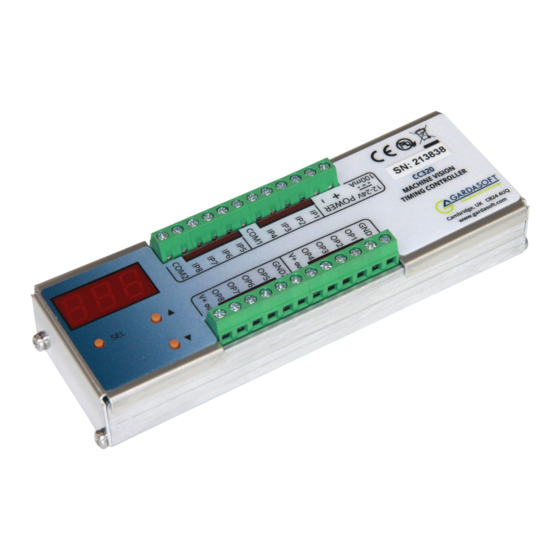
- Page 1 CC320 Trigger Timing Controller User Manual Version 015 www.gardasoft.com...
- Page 2 Deliberate acts of endangerment and vandalism are not covered by this document and must be considered by the installer. While care has been taken in the preparation of this document Gardasoft Vision Ltd will not accept any liability for consequential loss of any kind except those required by law.
-
Page 3: Table Of Contents
Mounting Connections Power supply Digital inputs Digital outputs Ethernet connector Connecting a CC320 to other devices 6.5.1 Connecting the output to a 24V input 6.5.2 Connecting the input to a 24V output 6.5.3 Connecting the output to an opto-coupled input 6.5.4... - Page 4 6.5.7 Connecting the output to a TTL input 6.5.8 Connecting the input to a TTL output 6.5.9 Connecting the input to an LVDS output 6.5.10 Connecting the output to an LVDS input 6.5.11 Connecting the output to an RS422 input 6.5.12 Connecting the input to an RS422 output Operation Input modes...
- Page 5 General setup page Command configuration 10.1 Communication 10.2 Command structure 10.3 Commands 10.4 Command summary Appendix A - Timing Appendix B - Error codes Appendix C - Examples Integrating smart cameras Sequenced pulses Gated pulses Delayed signal Belt position triggering www.gardasoft.com...
- Page 6 Pulse burst Simple FIFO mode Resync mode Resync and FIFO mode Appendix D - Configuration sheet...
-
Page 7: Getting Started
Three indicator LEDs on the outputs should be pulsing in sequence every second. Connect Ethernet to the CC320 and set it up according to Section 8, “Ethernet setup”. Use a web browser or the GardasoftMaint program (available from www.gardasoft.com) to configure the unit. -
Page 8: Electrical
CC320. General The CC320 must not be used in an application where its failure could cause a danger to personal health or damage to other equipment. If the equipment is used in a manner not specified by the manufacturer, the protection provided by the equipment may be impaired. -
Page 9: Allgemeines
L’utilisateur doit s’assurer que la différence de potentiel entre toute combinaison des signaux appliqués ne dépasse pas la tension de fourniture. Le CC320 ne dispose pas de système complet d’isolation des entrées et sorties. Les transitoires causés par les charges inductives doivent être supprimés à... -
Page 10: Général
Ensure the mounting screws protrude no further than 6mm from the surface to which the CC320 is to be attached. The PP703 kit is available for mounting the CC320 on a DIN rail. The dimensions in the diagrams below are all in millimetres. -
Page 11: Connections
The CC320 does not have an IP rating and should be mounted such that moisture and dirt cannot enter the unit. The CC320 is a fire enclosure as long as the following conditions are met: The Ethernet connector must not be facing downwards and, »... -
Page 12: Power Supply
Power supply The power supply must be 12VDC to 24VDC regulated. The maximum current required is 100mA. The maximum heat dissipation is 2.4W. Caution: Do not connect a power supply to the V+out connections. This is a low power reference voltage. Digital inputs The state of each input is shown on an LED next to the connector. -
Page 13: Digital Outputs
The CC320 inputs are optically coupled and the equivalent circuit is shown below: An input voltage between 5V and 24V is recognised by the CC320 as a logic level ‘1’. An input voltage of 2V or less is recognised as a logic level ‘0’. - Page 14 V+out Caution! Do not connect a PSU to V+out The CC320 equivalent circuit for the output is shown below: The voltage between the output and ground must not be greater than 24V and the output can only sink up to 50mA.
-
Page 15: Ethernet Connector
It runs at 10Mbits per second. Connecting a CC320 to other devices Use the following examples to help you connect your CC320 to other devices in your system: 6.5.1 Connecting the output to a 24V input... -
Page 16: Connecting The Input To A 24V Output
6.5.2 Connecting the input to a 24V output 6.5.3 Connecting the output to an opto-coupled input... -
Page 17: Connecting The Input To An Opto-Coupled Output
6.5.4 Connecting the input to an opto-coupled output 6.5.5 Connecting the output to an open-collector input www.gardasoft.com... -
Page 18: Connecting The Input To An Open-Collector Output
6.5.6 Connecting the input to an open-collector output 6.5.7 Connecting the output to a TTL input... -
Page 19: Connecting The Input To A Ttl Output
6.5.8 Connecting the input to a TTL output 6.5.9 Connecting the input to an LVDS output www.gardasoft.com... -
Page 20: Connecting The Output To An Lvds Input
6.5.10 Connecting the output to an LVDS input... -
Page 21: Connecting The Output To An Rs422 Input
6.5.11 Connecting the output to an RS422 input www.gardasoft.com... -
Page 22: Connecting The Input To An Rs422 Output
6.5.12 Connecting the input to an RS422 output Operation The CC320 Trigger Timing Controller has eight digital inputs, eight physical outputs, and eight virtual outputs (see Section 7.5, “Virtual channels”). All outputs operate independently and are configured separately. Their configuration is very flexible to provide solutions for a wide variety of timing problems. -
Page 23: Input Modes
All input connections are general purpose inputs except for IP1 and IP2, which can be used for an encoder as well as for general inputs. 7.1.1 Encoder operation The CC320 supports two types of encoder; one wire and two wire. The table below summarises this. Maximum Mode... -
Page 24: Free Running Trigger
7.1.2 Free running trigger The internal input (IP0) can be used as a periodic trigger. The parameter shown below can be set by using the CC320 web pages or by using the RB1,p command (see Section 10.3, “Commands”): Parameter The period (inverse of frequency) of the simulated Period trigger. - Page 25 The channel can take any input, or the output of any other channel as it’s gate. The gate enables/disables the output of the channel. This can be selected using the CC320 web pages and using the pull-down menu. Alternatively the gate input source can be set using the g parameter of the ‘Set the output’...
- Page 26 Parameter Pulse delay Specifies the delay time from trigger to pulse output using the web interface Pulse Delay field or the p parameter of the Output Pulse Timing command RTc,p,d (see Section 10.3, “Commands”). Pulse width Specifies the width of the pulse output as a time period using the web interface Pulse Width field or the d parameter of the Output Pulse Timing command RTc,p,d (see Section 10.3, “Commands”).
- Page 27 The channel can take any input, or the output of any other channel as it’s gate. The gate enables/disables the output of the channel. This can be selected using the CC320 web pages and using the pull-down menu. Alternatively the gate input source can be set using the g parameter of the ‘Set the output’...
- Page 28 The channel can take any input, or the output of any other channel as its trigger. This can be configured using the CC320 web pages and selecting a trigger source using the pull down menu. Alternatively the trigger input source can be set using the i parameter of the ‘Set the output’...
- Page 29 The channel can take any input, or the output of any other channel as it’s gate. The gate enables/disables the output of the channel. This can be selected using the CC320 web pages and using the pull-down menu. Alternatively the gate input source can be set using the g parameter of the ‘Set the output’...
- Page 30 The channel can take any input, or the output of any other channel as it’s gate. The gate enables/disables the output of the channel. This can be selected using the CC320 web pages and using the pull-down menu. Alternatively the gate input source can be set using the g parameter of the ‘Set the output’...
- Page 31 The channel can take any input, or the output of any other channel as its trigger. This can be configured using the CC320 web pages and selecting a trigger source using the pull down menu. Alternatively the trigger input source can be set using the i parameter of the ‘Set the output’...
- Page 32 Parameter Gate input The gate input is ignored in this mode. Pulse delay Specifies the number used to divide the trigger pulse by. Set by using the web interface Pulse Delay field or the p parameter of the Output Pulse Timing command RTc,p,d (see Section 10.3, “Commands”).
- Page 33 Trigger input The burst can be triggered by any input, or the output of any other channel. This can be configured using the CC320 web pages and selecting a trigger source using the pull down menu. Alternatively the trigger input source can be set using the i parameter of the ‘Set the output’...
- Page 34 Parameter Gate input The gate input sets the number of pulses in a burst of pulses. 1 to 24 can be selected using the CC320 web pages’ pull-down menu. Input IP1 to IP8 for 1 to 8 pulses Output 1 to Output 8 for 9 to 16 pulses Output 9 to Output 19 for 17 to 24 pulses.
- Page 35 The channel can take any input, or the output of any other channel as it’s gate. The gate enables/disables the output of the channel. This can be selected using the CC320 web pages and using the pull-down menu. Alternatively the gate input source can be set using the g parameter of the ‘Set the output’...
- Page 36 The channel can take any input, or the output of any other channel as it’s gate. The gate enables/disables the output of the channel. This can be selected using the CC320 web pages and using the pull-down menu. Alternatively the gate input source can be set using the g parameter of the ‘Set the output’...
- Page 37 Trigger input The burst can be triggered by any input or any other channel. This can be configured using the CC320 web pages and selecting a trigger source using the pull down menu. Alternatively the trigger input source can be set using the i parameter of the ‘Set the output’...
- Page 38 Parameter Gate input The gate input sets the number of pulses in a burst of pulses. 1 to 24 can be selected using the CC320 web page’ pull down menu. Input IP1 to IP8 for 1 to 8 pulses Output 1 to Output 8 for 9 to 16 pulses Output 9 to Output 19 for 17 to 24 pulses.
- Page 39 In this mode, the gate input is used as a start count signal. It can take any input, or the output of any other channel. This can be selected using the CC320 web pages and using the pull-down menu. Alternatively the gate input or source of the start signal can be set using the g parameter of the ‘Set the output’...
- Page 40 Specifies which input is used for triggering. The channel can take any input, or the output of any other channel. This can be configured using the CC320 web pages and selecting a trigger source using the pull down menu. Alternatively the trigger input source can be set using the i parameter of the ‘Set the output’...
- Page 41 The gate input is used to enable the function. The channel can take any input, or the output of any other channel as it’s gate input. This can be selected using the CC320 web pages and using the pull-down menu. Alternatively the gate input or source of the start signal can be set using the g parameter of the ‘Set the output’...
- Page 42 The gate input is used to enable the function. The channel can take any input, or the output of any other channel as it’s gate input. This can be selected using the CC320 web pages and using the pull-down menu. Alternatively the gate input or source of the start signal can be set using the g parameter of the ‘Set the output’...
- Page 43 The channel can take any input, or the output of any other channel as its trigger input. This can be configured using the CC320 web pages and selecting a trigger source using the pull down menu. Alternatively the trigger input source can be set using the i parameter of the ‘Set the output’...
- Page 44 The channel can take any input, or the output of any other channel as its trigger input. This can be configured using the CC320 web pages and selecting a trigger source using the pull down menu. Alternatively the trigger input source can be set using the i parameter of the ‘Set the output’...
-
Page 45: Flags
If a gate input is specified, the input specified, the input must be high to must be low to enable enable triggers. triggers No Ethernet message. Send message on Ethernet when triggered. See Section 7.3.1, “Ethernet message flag (E)”. www.gardasoft.com... -
Page 46: Ethernet Message Flag (E)
(P)”. 7.3.1 Ethernet message flag (E) When the CC320 is used to trigger a camera, the image processing can either be triggered by the acquisition of an image or by an Ethernet message sent from the CC320. When a trigger is received it is assigned a unique tag number (an incrementing number from 0 to 255). -
Page 47: Fifo Flag (F)
If the FIFO flag is not set, then an output cannot be re-triggered until the previous pulse has completed. Others triggers in this time are ignored If the FIFO flag is set, then multiple triggers are stored in the CC320 and a pulse is generated for each trigger at the correct time. -
Page 48: Logic Operations
Resync mode, the CC320 defaults to rejecting the product. Logic Operations It is possible to configure the CC320 trigger timing controller to conduct simple logic operations based on two inputs. The operators that can be achieved are NOT, AND, NAND, OR, and NOR. The output mode must be set to Mode 10 - Buffer T mode (buF), which makes the output the same signal as the input. -
Page 49: Nand
If IP1=1, and IP2=0, then OP1=1 If IP1=1, and IP2=1, then OP1=0 O (2) 7.4.4 OR Use the configuration below to set up a NAND operation such that: If IP1=0, and IP2=0, then OP1=0 If IP1=0, and IP2=1, then OP1=1 www.gardasoft.com... -
Page 50: Nor
If IP1=0, and IP2=1, then OP1=0 If IP1=1, and IP2=0, then OP1=0 If IP1=1, and IP2=1, then OP1=0 I, O, Virtual channels In addition to its eight physical channels, the CC320 has a further eight virtual channels. These are numbered from 9 to 16. -
Page 51: Cold Boot
12. Cold boot A cold boot function is available to reset the CC320 to a known state. The unit can be cold booted as follows: Press and hold the SEL and buttons when powering up the unit Sending an Ethernet command »... -
Page 52: Ethernet Setup
Connection The Ethernet link uses a 10Base-T connection on an RJ45 connector. The CC320 is usually connected to a network switch, hub or router, but you can connect it directly into the network port on a PC . IP Address The CC320 needs an IP address to communicate over Ethernet. -
Page 53: Dhcp
Section 10, Command configuration. You can also open the selected controller’s web pages at the click of a button. For more information about the CC320’s web pages, see Section 9, “Web page configuration”. 8.2.1 DHCP Most networks use a DHCP server. If there is a PC on the network, you... -
Page 54: Fixed Ip Address
CC320s could be allocated addresses 192.168.1.201 and 192.168.1.202. Controller Search There is a search mechanism which allows any device to find all Gardasoft controllers on a local network. The replies will tell any host the following about each controller: Model »... -
Page 55: Web Page Configuration
An enquiry message is a UDP packet from source port 30310, destination port 30311 with the message body ‘Gardasoft Search’ (8-bit ASCII,13 characters). The message output by the CC320 is a UDP packet from source port 30311, destination port 30310. It is formatted as: Gardasoft,CC320,000000,111111111111,22222222... -
Page 56: Main Page
The Main Page (shown below) is the first to open when you access the CC320’s web pages. This gives the controller’s hardware and firmware revision levels and its serial number. It also contains links to the CC320’s other web pages. -
Page 57: General Setup Page
You can also enter any Ethernet command from Section 10, “Command configuration”. Command configuration The CC320 can be configured via the Ethernet connection using UDP or TCP/IP. www.gardasoft.com... -
Page 58: Communication
Several commands can be put into one command line by separating them by a semi-colon ( ; ). A carriage return character should be sent to terminate the command line. The CC320 send any replies to the commands and then send a > character to indicate that the command line has been completed. -
Page 59: Commands
Any changes made using Ethernet commands are not saved permanently until the AW command has been sent. 10.3 Commands Show the firmware version Outputs the version number of the firmware, for example ‘001’. Clear configuration Clears the configuration to the cold boot state. www.gardasoft.com... - Page 60 Save configuration Saves the configuration to non-volatile memory. When the CC320 is turned off and on, this configuration is restored. Show configuration The current configuration is shown. The first line gives the encoder mode and the internal trigger timing. Then the configuration of each of the outputs is given, one per line.
- Page 61 The reply is of the form: Err 45 Error 45 was the last error Err 0 No error has occurred since the last GR command Set/clear the web page password EY asc1, asc2, asc3, asc4, asc5, asc6 www.gardasoft.com...
- Page 62 This command sets the password required to access the web pages. If EY is entered on its own, then the password is cleared. There are six optional parameters, which are ASCII values for a password from one to six letters. A value of 65 is A, 66 is B, and so on up to 90, which is Z.
- Page 63 (1 to 8). is the re-trigger time or encoder pulses The re-trigger time is the minimum time from when an output is triggered to the next time. The mode should be set before the re- trigger time. For example: www.gardasoft.com...
- Page 64 RR4,10ms = Output 4 won’t accept another trigger until 10ms after the previous one. Set the internal free running trigger RB1,p Where: p is the period of the timer The internal timer is set to run at the specified time period. For example: RB1,1ms Set period to 1ms (1000Hz).
- Page 65 200 encoder counts have been received since the CC320 was turned on. The count is a 32 bit unsigned number and wraps to 0 when it reaches 232. EN0 adjusts the encoder count backwards. It has the same effect as if the encoder moved backwards by the specified distance.
- Page 66 VL15 returns EN0,40 moves the encoder backwards by a count of 40. VL4294967271 returns because the count has wrapped to 2 – 25. Show the state of an input Where: i is the input channel (1 to 8). The command returns if the input is logic 0 and if the input is on.
-
Page 67: Command Summary
= 0 to enable the keyboard, and 1 to disable the keyboard. 10.4 Command summary Command Function syntax Show the firmware version. Clear all configuration. Show configuration. Make configuration non-volatile. Read any error messages Enable Ethernet messages. EYa1,a2 Set web page password to ‘AB’. www.gardasoft.com... -
Page 68: Appendix A - Timing
Pulse widths above 4ms are repeatable to within 100us and are subject to variation. When the CC320 is in Mode 2 - Pulse TT (Ptt), pulses in the following conditions have higher priority and better timing:... -
Page 69: Appendix B - Error Codes
Unable to read the EEPROM. Err 6, Err 12, EEPROM corrupt. The configuration has been Err 16 cleared. Err 8, Err 25 Unable to read settings from the EEPROM. Err 9, Err 17 Unable ta save settings to the EEPROM. www.gardasoft.com... -
Page 70: Appendix C - Examples
(at different positions), and a reject gate. The sensor is on IP3 of the CC320. Camera 1 is triggered by OP1 and pulses IP4 to show a pass. Camera 2 is triggered by OP2 and pulses IP5 to show a pass. The reject gate is pulse-to-accept on OP3. -
Page 71: Sequenced Pulses
The leading edge of IP1 is used as the trigger. OP1 triggers the first camera after 100ms. OP2 triggers the second camera after 200ms. Both camera triggers are positive pulses. The configuration details are shown below: 100ms 100µs 200ms 100µs www.gardasoft.com... -
Page 72: Gated Pulses
Both outputs are set to pulse mode. Two different delays give the timing difference between the two cameras (see overleaf). Gated pulses A camera needs to be triggered at 25Hz continuously, except when IP1 is high to indicate that the machine has stopped. The camera is triggered on OP1. -
Page 73: Delayed Signal
IP3 is the input from the sensor and OP2 is the signal to turn the » light on and off. OP2 has the same signal as IP3, but delayed by 1000 encoder counts. The two examples can be implemented using the following configuration: 500ms 0µs www.gardasoft.com... -
Page 74: Belt Position Triggering
1000 encoder 0µs counts Belt position triggering On a conveyor with an encoder, a sensor detects product presence. There are two cameras which are to take an image at fixed distances along the belt. The camera trigger pulses must be fixed width for exposure control. - Page 75 OP1 to OP4 are pulsed for 40ms in sequence. As each output is pulsed, OP5 is also pulsed for a short time to trigger the camera (gate input set to 4 specifies four pulses). The timing diagram is shown overleaf: www.gardasoft.com...
- Page 76 A sensor on IP1 detects the presence of a product . After a delay, OP1 triggers a camera. There may be several products between the sensor and the camera. The CC320 stores each of the triggers and then outputs a pulse after the correct delay. The configuration for this is shown below: 100µs...
- Page 77 Image processing software processes the image (which can take a variable length of time) and then sends a pass/fail message to the CC320. The pass/fail is re-synchronised to the original product presence and the reject gate is opened if necessary.
- Page 78 The camera trigger has the ‘Send trigger message’ flag set. So that when the product is detected, a message is send to the image processing software. The image processing software must use the GT command to receive these messages. The image processing has to send a pass/fail message before the reject gate is reached by the product.
- Page 79 Image processing software processes the image (which can take a variable length of time), and then sends a pass/fail message to the CC320. The pass/fail is re-synchronised to the original product presence and the reject gate is opened if necessary. The configuration details for...
- Page 80 The timing diagram is shown below: Appendix D - Configuration sheet The CC320 configuration sheet is illustrated below. A full-size copy can be downloaded from www.gardasoft.com.
- Page 81 This page is blank for your notes www.gardasoft.com...
- Page 82 Version 015 - April 2023 © Copyright 2023 Gardasoft Vision Ltd Gardasoft Vision Ltd Trinity Court Buckingway Business Park Cambridge, CB24 4UQ, UK +44 1954 234970 vision@gardasoft.com...
Need help?
Do you have a question about the CC320 and is the answer not in the manual?
Questions and answers