Table of Contents
Advertisement
Quick Links
Advertisement
Table of Contents

Related Manuals for GARDASOFT PP520


Summary of Contents for GARDASOFT PP520
- Page 1 PP520 LED Lighting Controllers Issue 018 User manual www.gardasoft.com...
- Page 2 Deliberate acts of endangerment and vandalism are not covered by this document and must be considered by the installer. While care has been taken in the preparation of this document Gardasoft Vision Ltd will not accept any liability for consequential loss of any kind except those required by law.
-
Page 3: Table Of Contents
PP520 LED lighting controllers - User Manual Contents Getting started Safety Heat Electrical General Installation guidance (disclaimer) Sicherheit Wärme Elektrik Allgemein Installationsanleitung (Haftungsausschluss) Sécurité Chaleur Électricité Généralités Guide d'installation (clause de non-responsabilité) General description Output modes 5.1.1 Continuous 5.1.2 Pulsed 5.1.3... - Page 4 PP520 LED lighting controllers - User Manual 10.3 Front panel Ethernet set up 10.4 Reading an IP address Webpage configuration 11.1 Main page 11.2 Configuration page 11.3 General setup page Command configuration 12.1 Command structure 12.2 Lighting commands 12.3 Command summary Reference information 13.1...
-
Page 5: Getting Started
DIN rail or the mounting holes. In particular, read the notes on heatsinking Section 7, PP520 heat output. Connect the PP520 up to a supply and an LED lighting unit as described in Section 8, Connections. When the PP520 powers up, it should show two alternating lines on the display to indicate that it is operating properly. -
Page 6: Safety
Reference information). At its maximum ratings, the PP520's enclosure can exceed 75°C which is sufficient to cause a burn if touched. Place in a position where personnel cannot accidentally touch it and ensure there is a free flow of air around the unit. -
Page 7: General
General The PP520 must not be used in an application where its failure could cause a danger to personal health or damage to other equipment. If the equipment is used in a manner not specified by the manufacturer, the protection provided by the equipment may be impaired. -
Page 8: Sicherheit
Berührung durch das Personal ausgeschlossen ist und stellen Sie sicher, dass Luft frei um das Gerät zirkulieren kann. Elektrik Das PP520 erzeugt Impulse mit hoher Energie. Achten Sie darauf, die Ausgänge korrekt anzuschließen und schützen Sie die Ausgangsverkabelung und Last gegen Kurzschlüsse. Beim Ausschalten bleibt Energie für etwa 15 Sekunden im PP520 gespeichert. - Page 9 Schalter als Teil der Installation in der Nähe vorsehen, mit dem die Steuerung an beiden Stromleitern von ihrer Stromquelle getrennt werden kann. Durch induktive Lasten verursachte Einschaltstöße zum PP520 müssen extern unterdrückt werden. Warnung: Es handelt sich hierbei um ein Produkt der Klasse A. Die Verwendung in Wohngebieten kann zu Funkstörungen führen und eine...
-
Page 10: Allgemein
PP520 LED lighting controllers - User Manual Allgemein Das PP520 darf nicht in Anwendungen eingesetzt werden, bei denen es durch einen Ausfall des Geräts zu einer Gefahr für die Gesundheit von Personen oder zur Beschädigung anderer Geräte kommen könnte. Wenn das Gerät in einer anderen als der vom Hersteller vorgesehenen Weise verwendet wird, kann die Schutzvorrichtung des Geräts... -
Page 11: Sécurité
PP520 LED lighting controllers - User Manual Sécurité Lisez ce document avant d'utiliser le PP520 Respectez les mesures de sécurité suivantes en toutes circonstances. En cas de doute, contactez votre distributeur ou Gardasoft Vision. Les symboles ci-dessous auront la signification suivante:... -
Page 12: Généralités
émissions à un niveau qui permet la réception des transmissions diffusées. Généralités Le PP520 ne doit pas être utilisé dans une application où la santé des personnes et l'intégrité des équipements seraient mises en danger s'il venait à tomber en panne. -
Page 13: Guide D'installation (Clause De Non-Responsabilité)
Ces informations sont seulement à titre indicatif. Les installateurs doivent effectuer leur propre évaluation des risques, pour chaque installation. Même si Gardasoft Vision Ltd a préparé minutieusement ces conseils, Gardasoft Vision Ltd et Gardasoft LLC décline toute responsabilité pour tout dommage, quel qu'il soit, à l'exception de ceux requis par la loi. La mise en péril volontaire ainsi que les actes de vandalisme ne sont pas... -
Page 14: General Description
Currents can be specified in 2.5mA steps to give very fine control of intensity. You can set the PP520 up using either the buttons on the front panel (see Section 9, Front panel... -
Page 15: Switched
This flag inverts the trigger sense. In pulse mode with the P flag set, the PP520 triggered on the rising edge of the trigger pulse. If the flag is not set, it triggers on the falling edge. The falling edge may give a slower response time. -
Page 16: Cold Start
PP520 LED lighting controllers - User Manual Cold start To clear the configuration to the default settings, turn on the PP520 while holding the SEL and q buttons for about 5 seconds, until displayed. Both channels are set up for 50% intensity and continuous operation. -
Page 17: Mechanical Fixing
Likewise leave a similar space between the PP520 and any parts which could be affected by high temperatures. The enclosure of the PP520 is used to dissipate power in the form of heat. For this reason the material to which the unit is attached must be suitable, preferably metallic with ability to dissipate the produced heat. - Page 18 PP520 LED lighting controllers - User Manual To avoid a fire hazard, consider the implications of overheating in the unlikely event of a fault in the PP520. The power dissipation in a fault condition is approximately given by the sum of the following for the two...
-
Page 19: Pp520 Heat Output
PP520 LED lighting controllers - User Manual PP520 heat output The PP520 controller has a linear circuit to produce constant current output. This section explains how to calculate the heat output from the PP520 and what measures you can take to manage it. -
Page 20: Total Heat Output
PP520 LED lighting controllers - User Manual Total heat output The total heat output from the PP520 is given by adding the heat output for both channels as calculated above. There are several ways to reduce the heat output from the PP520: Use pulse mode. -
Page 21: Connections
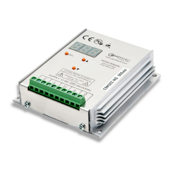
PP520 LED lighting controllers - User Manual Connections All connections to the 520 (except Ethernet) are made on screw terminals at one end of the case (see below). The screw terminals have the following connections: Screw terminal ID Function TRIG1– Channel 1 trigger input... -
Page 22: Triggers
PP520 LED lighting controllers - User Manual Triggers The PP520 triggers are opto-coupled as shown in the circuit below. A voltage between 4.5V to 24V provides a logic 1 and any V TRIG TRIG voltage below 1V, a logic 0. Typically the value of V is 1.5V. -
Page 23: Front Panel Configuration
The Autosense feature detects the presence of a light and prompts you to set the rating as follows: When the PP520 detects a light connected to channel 1 for the first time, Sn1 is displayed. (A light connected to channel 2 will display Sn2). -
Page 24: Setting Up Continuous Output
PP520 LED lighting controllers - User Manual The PP520 displays a pattern of alternating horizontal bars when the light is operating normally. If you power cycle the controller, it will resume with the same settings. Other displays are shown for channel 2 connected, and channels 1 and 2 connected. -
Page 25: Setting Up Switched Output
PP520 LED lighting controllers - User Manual Use the p and q buttons to select SCo and press the SEL button. bri is displayed. Press the SEL button. Use the p and q buttons to set the intensity from 1% to 99.9%, and press the SEL button. -
Page 26: Setting Up Pulsed Operation
PP520 LED lighting controllers - User Manual Use the p and q buttons to select SOn and press the SEL button. bri is displayed. Press the SEL button. Use the p and q buttons to set the intensity from 1% to 99.9%, and press the SEL button. - Page 27 PP520 LED lighting controllers - User Manual Use the p and q buttons to select SPu and press the SEL button. bri is displayed. Press the SEL button. Use the p and q buttons to set the intensity from 1% to 999%, and press the SEL button.
-
Page 28: Setting Pulse Delay And Width Times
Your PP520 is ready to use. Setting pulse delay and width times When the PP520 displays numeric values you can change, the right hand digit flashes. You can then use the p and q buttons to set the required value. - Page 29 Press the SEL button. Use the p and q buttons to select E-5 to enter values from 0.02ms to 9.98ms in steps of 0.02ms using a PP520 or 0.01ms to 9.99ms in steps of 0.01ms using a PP520F. Press the SEL button.
- Page 30 PP520, or 1μs to 999μs in steps of 1μs using a PP520F. Press the SEL button. Use the p and q buttons to select the desired value. Press the SEL button. Note: When a light is pulsed, the PP520 shows that a trigger has occurred by displaying in the display window. — —...
-
Page 31: Ethernet Communication
Connection The Ethernet link uses a 10Base-T connection on an RJ45 connector. The PP520 is usually connected to a network switch, hub or router, but you can connect it directly into the network port on a PC using a crossover cable. -
Page 32: 10.2.1 Dhcp
Section 12, Command configuration. You can also open the selected controller's web pages at the click of a button. For more information about the PP520's web pages, refer to Section 11, Webpage configuration 10.2.1 DHCP Most networks use a DHCP server. - Page 33 PP520 LED lighting controllers - User Manual Use the p and q buttons to select FIP and press the SEL button. IP1 is displayed. Press the SEL button and use the p and q buttons to select the first three digits of the IP address. Press the SEL button again.
- Page 34 PP520 LED lighting controllers - User Manual Sb1 is displayed. Press the SEL button and use the p and q buttons to select the first three digits of the subnet mask. Press the SEL button again. Sb2 is displayed. Press the SEL button and use the p and q buttons to select the second three digits of the subnet mask.
-
Page 35: Reading An Ip Address
PP520 LED lighting controllers - User Manual gt2 is displayed. Press the SEL button and use the p and q buttons to select the second three digits of the gateway address. Press the SEL button again. gt3 is displayed. Press the SEL button and use the p and q buttons to select the third three digits of the gateway address. - Page 36 IP3 is displayed. Press the SEL button to read the third three digits of the IP address. Press the SEL button again. IP4 is displayed. Press the SEL button to read the remaining digits of the IP address. Press the SEL button again. Your PP520 is ready for normal operation. — —...
-
Page 37: Webpage Configuration
PP520 LED lighting controllers - User Manual Webpage configuration You can set up the PP520 through its own internal web pages. Click the Open webpage... button in GardasoftMaint to take you directly to the PP520's webpages. You can also type the controller’s IP address (displayed in GardasoftMaint) into your web browser, which will display the Main screen. -
Page 38: Configuration Page
There is one configuration page for each output channel as shown below: You can set up all the parameters for each output channel. Pressing the Submit button updates the PP520 configuration and saves the changes to non-volatile memory. On this page you can: Change the current rating and brightness of the light. -
Page 39: General Setup Page
PP520 LED lighting controllers - User Manual 11.3 General setup page The general setup page (shown below) allows you to set up or clear the webpage's password and set up the internal trigger. You can also enter any Ethernet command from Section 12, Command configuration. -
Page 40: Command Configuration
Several commands can be put into one command line by separating them by a semi-colon ( ; ).The PP520 sends any replies to the commands followed by a > character to show that the command line has completed. - Page 41 PP520 LED lighting controllers - User Manual Save the settings to memory Once the settings are saved to memory, they are retained when the unit is switched off. If this is not done, the changes to the settings are volatile, and if the unit is switched off they revert to the settings in force when the last AW command was issued.
- Page 42 If Ethernet messages are not enabled, the last event or error number can be read by this command. Any error displayed on the unit is cleared, so if there was a lighting error, the PP520 resumes auto- sensing on that channel.
-
Page 43: Lighting Commands
PP520 LED lighting controllers - User Manual Report the version of firmware running in the PP520 This command returns the firmware version. For example: PP420 (HW001) V029 Disable keyboard KBd,c Where: = 0 to enable the keyboard = 1 to disable the keyboard... - Page 44 PP520 LED lighting controllers - User Manual Set continuous mode The output is set to continuous mode at a percentage of full brightness: RSc,s Where: output channel (1 or 2) setting in percent (0 to 100) Set switched mode The output is set to continuous mode at a percentage of full...
-
Page 45: Command Summary
PP520 LED lighting controllers - User Manual Simulate an input trigger This command simulates a trigger pulse. If the channel is in pulse mode, it will pulse and show in the display. Where c = the input channel to be pulsed (1 or 2) Set an internal trigger This command enables or disables the internal trigger. - Page 46 PP520 LED lighting controllers - User Manual Command Example Effect RS2,65 Set channel 2 to 65% brightness continuous. RW1,50 Set channel 1 to 50%, switched by trigger 1. RT2,3,4,50 Set channel 2 to 3ms pulses, delayed by 4ms, at 50% brightness.
-
Page 47: Reference Information
10A pulsed Ambient temperature 5°C to 40°C The ambient temperature may need to be during operation lower if the PP520 is dissipating a lot of heat. Total allowed power 8W maximum See Section 7, PP520 heat output. dissipation without heat... -
Page 48: Error Codes
For example, sending an RT command with a delay of 0 will get a reply of 'Err 5'. When the settings are viewed the delay will have been set to 20μs (PP520) or 4μs (PP520F). Err 8, 12 EEPROM corrupt. - Page 49 Error Reason number Fatal: The PP520 is too hot. The PP520 is fitted with a thermal cut-out. If the internal temperature reaches 62°C (corresponding to a case temperature of 70°C), the outputs are turned off. This message is displayed until the PP520 has cooled down to below 62°C.
- Page 50 PP520 LED lighting controllers - User Manual Issue 018 - April 2017 © Copyright 2017 Gardasoft Vision Ltd Gardasoft LLC Gardasoft Vision Ltd Oak Ridge Road Trinity Court Weare Buckingway Business Park New Hampshire Cambridge CB24 4UQ UK 03281 USA tel: +44 1954 234970...
Need help?
Do you have a question about the PP520 and is the answer not in the manual?
Questions and answers