
Related Manuals for GARDASOFT RC1 Series


Summary of Contents for GARDASOFT RC1 Series
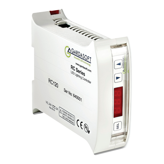
- Page 1 RC1xx LED Lighting Controllers - User Manual RC100/120 LED Lighting Controllers Issue 007 User manual www.gardasoft.com...
- Page 2 Deliberate acts of endangerment and vandalism are not covered by this document and must be considered by the installer. While care has been taken in the preparation of this document Gardasoft Vision Ltd will not accept any liability for consequential loss of any kind except those required by law.
-
Page 3: Table Of Contents
RC1xx LED Lighting Controllers - User Manual Contents Getting started RC1xx features - a summary Safety precautions Heat Electrical General Installation guidance (disclaimer) Sicherheitsvorkehrungen Hitze Elektrik Allgemeines Haftungsausschluss Mesures de sécurité Chaleur Électricité Général Clause de non-responsabilité Mounting the RC1xx Environmental considerations Connecting the RC1xx Power... - Page 4 RC1xx LED Lighting Controllers - User Manual Ethernet address (RC120) IP address 8.1.1 DHCP 8.1.2 Fixed IP address Automatic sensing Web page configuration (RC120) Main page Configuration page General setup page Configuration commands 10.1 Lighting setup 10.2 Front panel commands 10.2.1 Startup 10.2.2 Setting the light rating 10.2.3 Setting up continuous output 10.2.4...
-
Page 5: Getting Started
Safety precautions Read this before using the RC1xx. Always observe the following safety precautions. If in doubt, contact Gardasoft Vision Ltd. The following symbols are used in this guide: Warning: Read the instructions to understand the possible hazards. -
Page 6: Heat
This information is for guidance only. Installers must perform their own risk assessment specific to each installation. While Gardasoft Vision Ltd has taken every care in the preparation of this advice, Gardasoft Vision Ltd accepts no liability for damages of any kind except those required by law. -
Page 7: Hitze
RC1xx LED Lighting Controllers - User Manual Warnung: Lesen Sie die Hinweise, um eine mögliche Gefahr zu verstehen. Warnung: Oberfläche kann heiß werden. Warnung: Mögliche gefährliche Spannung. Wenn diese Symbole in dieser Anleitung erscheinen, finden Sie im beistehenden Text die zu ergreifenden Vorsichtsmaßnahmen. Hitze Stellen Sie sicher, dass die RC1xx ordnungsgemäß... -
Page 8: Haftungsausschluss
Dokument nicht abgedeckt und sind vom Monteur zu berücksichtigen. Mesures de sécurité Veuillez lire la notice avant d’utiliser le RC1xx. Respectez toujours les mesures de sécurité qui suivent. En cas de doute, contactez Gardasoft Vision Ltd. Les symboles suivants sont utilisés dans ce manuel: Attention: Lisez les instructions pour comprendre quels sont les risques éventuels. -
Page 9: Général
Ces informations sont seulement à titre indicatif. Les installateurs doivent établir leur propre évaluation de risques pour chaque installation. Gardsoft Vision a préparé minutieusement ces conseils, mais Gardasoft Vision déclinent toute responsabilité concernant les dommages de toute nature à l’exception de ceux requis par la loi. -
Page 10: Connecting The Rc1Xx
RC1xx LED Lighting Controllers - User Manual The RC1xx has an ingress rating of IP20 and it should be sited so that water or dirt cannot enter the unit. Connecting the RC1xx Refer to Section 11, “RC1xx reference information” for the ratings of the connections. -
Page 11: Trigger Input
RC1xx LED Lighting Controllers - User Manual The lighting output connections must not be commoned to any other controllers or grounded in any way. The connections are shown below: Trigger input The trigger input is a Smart Input; it accepts a range of trigger sources with minimal extra circuitry. -
Page 12: Ethernet
RC1xx LED Lighting Controllers - User Manual Ethernet The RJ45 connector fitted to the RC120 requires a straight-through cable to connect to a network switch, hub or router. The connection is 10Base-T and operates at 10MBits per second. Connectors (general) The connectors required to mate with the RC1xx controller’s connectors are as follows: Connector... -
Page 13: Triggering
RC1xx LED Lighting Controllers - User Manual soon after the previous trigger. The maximum pulse width and duty cycles are shown below: Output Maximum Maximum brightness pulse width duty cycle 0 to 100% 100ms 100% 101% to 200% 30ms 201% to 300% 10ms 301% to 500% 501% to 1000%... -
Page 14: Trigger Input Options
RC1xx LED Lighting Controllers - User Manual 7.2.1 Trigger input options You can connect the following types of trigger to the Smart Input: 3V to 24V voltage source Any voltage between 0V and 0.9V is taken as logic 0. Any voltage between 3V and 24V is taken as logic 1. -
Page 15: Internal Trigger
The unit does not need to sense the light again unless the light has changed or the RC1xx has been power-cycled. For further information on this feature, see the application note, APP936 – SafeSense Technology, available from www.gardasoft.com. SafePower The RC1xx’s SafePower needs no intervention from the user for its operation. -
Page 16: Current Adjust
RC1xx LED Lighting Controllers - User Manual specified brightness limit when the light is characterised. This is called the characterisation limit. The measured overdrive voltage and current relationship is stored in the RC120 and allows it to respond much more rapidly to new overdrive parameters up to that limit. -
Page 17: Fault Detection
You may need to ask your network administrator for advice about setting up the Ethernet connection. The application note APP923 – Troubleshooting Ethernet problems is available from www.gardasoft.com/Downloads. The Ethernet set up of the RC120 is not affected by cold-booting the controller. -
Page 18: Ip Address
DHCP mode or the IP address can be set or read using the GardasoftMaint program available from www.gardasoft.com. The GardasoftMaint window is shown below: GardasoftMaint allows you to view the controllers on your network, change their IP addresses and upgrade their firmware if it becomes necessary. -
Page 19: Fixed Ip Address
IP address. An enquiry message is a UDP packet from source port 30310, destination port 30311 with the message body ‘Gardasoft Search’ (8-bit ASCII, 16 characters). The message output by the RC12x is a UDP packet from source port 30311, destination port 30310. -
Page 20: Web Page Configuration (Rc120)
IP address (displayed in GardasoftMaint) into your web browser, which will display the Main page. GardasoftMaint software is available from www.gardasoft.com. Main page The main page (shown below) is the first to open when you access the RC120’s web pages. -
Page 21: General Setup Page
RC1xx LED Lighting Controllers - User Manual The configuration page is shown below: General setup page On the general setup page (shown below), you can set a password for the RC120 and send it commands. Refer to Section 10.3.3, “General commands”... -
Page 22: Configuration Commands
RC1xx LED Lighting Controllers - User Manual Configuration commands In addition to configuring the RC120 using its web page interface, you can configure it from the front panel or using the Ethernet connection. Both of these methods are described in this section along with general information about setting up lights. - Page 23 RC1xx LED Lighting Controllers - User Manual When the RC1xx is not being configured, the display shows the status of the lighting output as shown below: The RC1xx displays an error if a light is connected but no rating specified. To configure the RC1xx from the front panel, press and hold SEL for 1 second.
-
Page 24: Setting The Light Rating
RC1xx LED Lighting Controllers - User Manual 10.2.2 Setting the light rating Press and hold SEL for 1 second and follow the keystrokes below: CH1 is displayed. Use the and buttons to scroll to rAt. Press the SEL button. Use the ... -
Page 25: Setting Up Switched Output
RC1xx LED Lighting Controllers - User Manual 10.2.4 Setting up switched output Press and hold SEL for 1 second and follow the keystrokes below: CH1 is displayed. Press the SEL button. Use the and buttons to select SOn (other options displayed are SPu and SCo). -
Page 26: Setting Time Periods
RC1xx LED Lighting Controllers - User Manual dEL is displayed. Press the SEL button to set up the pulse delay time (refer to Section 10.2.6 “Setting time periods”). Press the SEL button to confirm the period set. PUL is displayed. Press the SEL button to set up the pulse width (refer to Section 10.2.6 “Setting time periods”). -
Page 27: Setting The Internal Trigger Timer
RC1xx LED Lighting Controllers - User Manual Follow the keystrokes below to enter numerical data into the RC1xx using the scheme shown. E-2 is displayed. Press the SEL button. Use the and buttons to select the required value in steps of 10ms. Press the SEL button. -
Page 28: Using The Key Lock
RC1xx LED Lighting Controllers - User Manual The internal trigger timer is set. 10.2.8 Using the key lock You can lock the RC1xx front panel keypad so unauthorised users cannot change the configuration. To do this you can set a numeric code from 0 to 255, which provides moderate protection. -
Page 29: Viewing The Trigger Status
RC1xx LED Lighting Controllers - User Manual 10.2.9 Viewing the trigger status You can view the trigger input status and whether the light is pulsing when the RC1xx is set to pulse or switched mode. To do this, press and hold SEL for I second and is displayed. -
Page 30: Ethernet Commands (Rc120)
10.3 Ethernet commands (RC120) You can configure the RC120 through the Ethernet connection using UDP or TCP/IP. You can download GardasoftMaint from www.gardasoft.com/ Downloads, which allows you to send commands to configure your RC120. 10.3.1 Ethernet communication Command lines can be sent from a client using TCP or UDP packets. They should be sent to destination port 30313. -
Page 31: General Commands
RC1xx LED Lighting Controllers - User Manual Numeric parameters are separated by a comma (,). Time periods are specified in milliseconds by default, but you can add ‘s’, ‘ms’, or ‘us’ to the parameter to specify seconds, milliseconds, or microseconds. Current is specified in amps by default, but you can add ‘A’... - Page 32 RC1xx LED Lighting Controllers - User Manual Where m = flags as follows: bit 1 = E flag set (error detection enabled) E flag cleared (error detection disabled) bit 2 = P flag set (positive triggers) P flag cleared (negative triggers) bit 3 = Autosense set (controller waits for light to be connected...
- Page 33 RC1xx LED Lighting Controllers - User Manual A typical reply to this command might be: CH1,MD0,S50.0,0.0,DL1.000ms,PU1.000ms,RT 0.0us,IP1,FL0,CS0.000A,RA0.000A Where: Channel number; this is always 1. Mode: 0 = continuous, 1 = pulsed, 2 = switched. Percentage brightness: 50.0 = 50%; the second part is always 0.0.
- Page 34 RC1xx LED Lighting Controllers - User Manual When Ethernet messages are enabled, any error reports are sent to the most recent UDP or TCP/IP address from which a command has been received. These messages take the form: Evtc,e Where: c = 1 for events concerning the light output, otherwise 0 e = the event value (see Section 11.3, “Event codes”) Clear any errors Use this command to read the last event or error code when Ethernet...
-
Page 35: Lighting Commands
RC1xx LED Lighting Controllers - User Manual 2 to disable the keypad and disallow the unlock code to be entered on the keypad. the unlock code, which must be a number from 0 to 255. You can still access the RC120’s settings using Ethernet commands and through its web pages. -
Page 36: Command Summary
RC1xx LED Lighting Controllers - User Manual Set switched mode This command sets the output to switched mode and allows the brightness to be set: RW1,s,w,r Where: s = brightness setting in percent (0 to 999) w = typical pulse width in ms (optional) r = likely period in ms (optional) The w and r parameters are optional and should only be used when the expected pulse width is >100ms and/or the period is >5 seconds. -
Page 37: Rc1Xx Reference Information
RC1xx LED Lighting Controllers - User Manual Command Example Effect RW1,50 Set the unit to 50% switch mode. RT1,3,4,50 Set the unit to 3ms pulses, delayed by 4ms, at 50% brightness. RE1,6 Set the unit to ignore lighting errors and make its trigger input active low. -
Page 38: Restrictions
RC1xx LED Lighting Controllers - User Manual RC100 RC120 Timing ±5µs (delay + pulse up to 60ms), otherwise ±50µs repeatability Switch mode 100µs maximum latency Trigger rate 100Hz maximum 24V DC ±10% regulated Supply voltage An SELV power supply is required 120mm long x 35mm wide x 101mm high Dimensions (excluding DIN fixing) -
Page 39: Event Codes
RC1xx LED Lighting Controllers - User Manual Because of this, fault detection is disabled and the following conditions apply: For pulse currents greater than 0.5A, the duty cycle is restricted to 1%. » For pulse currents less than or equal to 0.5A , the duty cycle is restricted »... -
Page 40: Error Codes
RC1xx LED Lighting Controllers - User Manual 11.4 Error codes Some error codes are displayed in the RC1xx’s front panel; these are shown in red. Error Reason number Err 1 A parameter value is invalid. Err 2 Command not recognised. Err 3 A numeric value is in the wrong format. - Page 41 RC1xx LED Lighting Controllers - User Manual Error Reason number Err 43, The requested output current requires too high a voltage. Err 44, Fatal error: The RC1xx is too hot. The unit has a thermal cut out which operates between approximately 65°C and 70°C depending on conditions.
- Page 42 RC1xx LED Lighting Controllers - User Manual Issue 007 - September 2021 © Copyright 2021 Gardasoft Vision Ltd Gardasoft Vision Ltd Trinity Court Buckingway Business Park Cambridge CB24 4UQ UK tel: +44 1954 234970 www.gardasoft.com...
Need help?
Do you have a question about the RC1 Series and is the answer not in the manual?
Questions and answers