Table of Contents
Advertisement
Quick Links
Advertisement
Table of Contents

Related Manuals for GARDASOFT CL190


Summary of Contents for GARDASOFT CL190
- Page 1 CL190/CL191 Lens Controller Issue 002 User manual www.gardasoft.com...
- Page 2 Deliberate acts of endangerment and vandalism are not covered by this document and must be considered by the installer. While care has been taken in the preparation of this document Gardasoft Vision Ltd will not accept any liability for consequential loss of any kind except those required by law.
-
Page 3: Table Of Contents
CL190/CL191 Lens Controller - User Manual Contents Getting started C190/CL191 features - a summary Safety Electrical General Sicherheit Elektrik Allgemeines Sécurité Électricité Général Mounting the CL191 Environmental considerations Connecting the CL191 General description Triggering 7.1.1 Trigger input options Flags Factory settings I2C communication I2C command structure... - Page 4 CL190/CL191 Lens Controller - User Manual — —...
-
Page 5: Getting Started
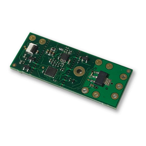
For any trouble-shooting problems, contact Gardasoft for support. C190/CL191 features - a summary The CL190/CL191 product is a single channel lens controller for use in machine vision applications. It works with the following ranges of Optotune lenses: EL-10-30... -
Page 6: Safety
CL190/CL191 Lens Controller - User Manual Safety Read this before using the CL191. Always observe the following safety precautions. If in doubt, contact your distributor or Gardasoft Vision. The following symbols mean: Warning: Read instructions to understand possible hazard Warning: Possible hazardous voltage. -
Page 7: Sicherheit
Sicherheit Bitte lesen Sie dieses Dokument, bevor Sie die CL191 verwenden. Beachten Sie immer die folgenden Sicherheitshinweise. Bei Fragen wenden Sie sich an Ihren Händler oder an Gardasoft Vision. Die folgenden Symbole bedeuten: Warnung: Lesen Sie die Anleitung, um die mögliche Gefahrenquelle zu verstehen. -
Page 8: Sécurité
Veuillez lire la notice avant d’utiliser le CL191 . Respectez toujours les mesures de sécurité qui suivent. En cas de doute, contactez votre distributeur ou Gardasoft Vision. Les symboles suivants signifient: Attention: Lisez les consignes afin de bien comprendre les dan- gers encourus. -
Page 9: Mounting The Cl191
CL190/CL191 Lens Controller - User Manual Mounting the CL191 The CL191 is mounted using a single M2 screw as shown in the illustration below: Environmental considerations The CL191 is a bare PCB and has no ingress rating. It should be sited away from water or dirt. -
Page 10: Connecting The Cl191
CL190/CL191 Lens Controller - User Manual Connecting the CL191 Refer to Section 10.1 , Specifications and ratings for the ratings of the connections. The CL191's connections are shown below: The CL191's UART and manufacturing test connections are on the underside of the PCB as shown below: The I2C connections to the CL191 are shown below: Power supplied to the CL191 must be in the range 4.5VDC to 5.5VDC. - Page 11 CL190/CL191 Lens Controller - User Manual The connections to the lens are normally made through the lens connector, although A1 Out and A2 Out are available from the PCB. The lens connector terminations are as follows: Connector pin Description A1 Out A2 Out 3.3VDC...
-
Page 12: General Description
CL190/CL191 Lens Controller - User Manual General description Three modes of operation are provided for the lens output: Continuous – the output is constant, and can be set to any value between the minimum and maximum optical power of the lens. -
Page 13: Trigger Input Options
CL190/CL191 Lens Controller - User Manual 7.1.1 Trigger input options You can connect the following types of trigger to the trigger input: 10V to 24V voltage source Any voltage between 0V and 0.9V is taken as logic 0. Any voltage between 10V and 24V is taken as logic 1. -
Page 14: Factory Settings
CL190/CL191 Lens Controller - User Manual Factory settings You can clear the CL191 configuration to return it to its factory settings. Clear the configuration by using the CL command (see Section 9 , Configuration commands). — —... -
Page 15: I2C Communication
CL190/CL191 Lens Controller - User Manual I2C communication The CL191 contains a master/slave protocol with a maximum frequency of 400khz. The address is 0x20 for writing and 0x21 for reading. I2C command structure The I2C protocol allows you to send command strings to the CL191 and to retrieve the results. - Page 16 CL190/CL191 Lens Controller - User Manual — —...
- Page 17 CL190/CL191 Lens Controller - User Manual After sending an I2C message, it is necessary to wait before reading the reply; I2C messages typically take 100ms for the reply to be ready. Some commands, including the RL commands, take 150ms before a reply is ready.
-
Page 18: Configuration Commands
When an error occurs, the host may request a reply message to be sent to it by using the GT command. Multiple commands can be entered on one line by separating them with a semi-colon (;). The CL190 replies to the commands individually, — —... -
Page 19: General Commands
CL190/CL191 Lens Controller - User Manual separating them with and adding the > prompt after the final <LF><CR> command reply. All commands comprise a code of two letters followed by any parameter necessary. All spaces in the command are ignored. - Page 20 Save the settings to memory This command saves the settings to non-volatile memory. If you power cycle the CL190 before sending the AW command, all changes are lost and the unit returns to the values set before the last AW command.
- Page 21 CL190/CL191 Lens Controller - User Manual Set lens with no EEPROM The CL190 will work with Optotune™ lenses having no internal EEPROM. This command allows the user to set the optical power and current rating for the lens. RM1,n,x,i,a Where:...
-
Page 22: Analog Mode Commands
An analog input voltage from 0V to 10V can be used to set the focal power of the lens connected to the CL190. The translation from input voltage to focal power can be linear or can be a non-linear profile. The non linearity is set up by the number of steps in a translation table and the value associated with each. - Page 23 CL190/CL191 Lens Controller - User Manual Set analog translation Non-linear translation can be used to convert the analog voltages from a distance sensor to an optical power to focus at the given distance. This command turns on non-linear translation and sets the number of steps in the non-linear translation.
-
Page 24: Waveform Commands
CL190/CL191 Lens Controller - User Manual Note that in this example 5V will give 2.5 diopters. Waveform commands Waveform mode generates a signal with a value from the active focus to the idle focus. Single shot waveforms run for one cycle when a trigger input signal is received. - Page 25 CL190/CL191 Lens Controller - User Manual Mode 4 Step sequence run continuously (trigger ignored). Mode 5 Square wave run once per trigger pulse. Mode 6 Square wave run continuously (trigger ignored). — —...
- Page 26 CL190/CL191 Lens Controller - User Manual Mode 7 Triangle wave run once per trigger pulse. Mode 8 Triangle wave run continuously (trigger ignored). Mode 9 Sawtooth wave run once per trigger pulse. — —...
- Page 27 CL190/CL191 Lens Controller - User Manual Mode 10 Sawtooth wave run continuously (trigger ignored). Mode 11 Sine wave run once per trigger pulse. Mode 12 Sine wave run continuously (trigger ignored). — —...
- Page 28 CL190/CL191 Lens Controller - User Manual Mode 13 Staircase wave run once per trigger pulse. Mode 14 Staircase wave run continuously (trigger ignored). Waveform commands RN1,m,p,s Where: mode (3 to 14; refer to the illustrations shown previously) period in milliseconds (50ms to 3s)
-
Page 29: Programmable Step Commands
CL190/CL191 Lens Controller - User Manual The following examples illustrate how these commands are used: RN1,1,100 Set as continuous square wave at 10Hz. RN1,8,50 Set a continuous triangle wave at 20Hz. RN1,11,10s Set a triggered sine wave which runs once for 10 seconds. - Page 30 CL190/CL191 Lens Controller - User Manual Set step sequence, single shot RN1,3,p Where: p = period (5ms to 30s) Set step sequence, continuous RN1,4,p Where: p = period (5ms to 30s) Status command An example of the information that could be returned on receipt of an ST command is given below:...
-
Page 31: Command Summary
CL190/CL191 Lens Controller - User Manual Command summary Command Example Effect Save changes. Clear configuration. Read the firmware version. RS1,6.5 Set the lens to 6.5 diopters. RA1,0 Set the lens to analog control mode. RA1,1,4 Set 4 points in the non-linear translation profile. -
Page 32: Cl191 Reference Information
CL190/CL191 Lens Controller - User Manual CL191 reference information This section of the user manual contains information about the CL191's specification, ratings and restrictions, and event and error codes. 10.1 Specifications and ratings CL191 Output One channel, including constant current lens drive channel and lens EEPROM data communications. -
Page 33: Restrictions
CL190/CL191 Lens Controller - User Manual CL191 Weight Standards CE, RoHS 10.2 Restrictions The maximum continuous output current is -250mA to +250mA. — —... -
Page 34: Error Codes
CL190/CL191 Lens Controller - User Manual 10.3 Error codes Error Reason number Err 1 A parameter value is invalid. Err 2 Command not recognised. Err 3 A numeric value is in the wrong format. Err 4 Wrong number of parameters. - Page 35 CL190/CL191 Lens Controller - User Manual This page is left blank for your notes: — —...
- Page 36 CL190/CL191 Lens Controller - User Manual Issue 002 - June 2018 © Copyright 2018 Gardasoft Vision Ltd Gardasoft LLC Gardasoft Vision Ltd Oak Ridge Road Trinity Court Weare Buckingway Business Park New Hampshire Cambridge CB24 4UQ UK 03281 USA tel: +44 1954 234970...
Need help?
Do you have a question about the CL190 and is the answer not in the manual?
Questions and answers