
Related Manuals for GARDASOFT TR-CL180


Summarization of Contents
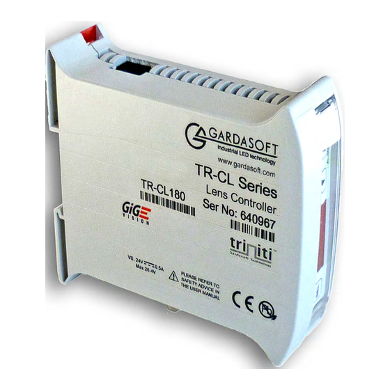
Getting Started with the TR-CL180
TR-CL180 Features Summary
Overview of the TR-CL180's capabilities and compatible Optotune lenses.
GigE Vision Compatibility
Explanation of GigE Vision compatibility for controller settings and interaction.
Safety Precautions
Electrical Safety
Details on voltage limits and isolation for electrical safety.
General Operational Safety
Precautions against misuse and damage to equipment or personnel.
Mounting and Environment
Environmental Considerations
Guidance on unit placement, ingress protection, and operating environment suitability.
Connecting the TR-CL180
Power Connection Details
Specifies the SELV power supply requirements and connection pinout.
Lens Output Connector
Describes the 6-way Hirose connector for Optotune lenses.
Trigger Input Options
Details on connecting various trigger sources like TTL, NPN, PNP.
Ethernet Connection Setup
Information on using RJ45 connectors and straight-through cables for Ethernet.
RS232 Communication Port
Configuration for the standard female 9-way DSUB RS232 connector.
General Connector Specifications
Lists required mating connectors for power, trigger, and lens output.
System Description
Triggering Modes and P Flag
Explains continuous, switched, and analog modes and the P flag's trigger sense inversion.
Trigger Input Signal Types
Details on 3V-24V, TTL, NPN, PNP, and opto-coupler trigger inputs.
Control Flags Explained
Description of E Flag for fault detection and P Flag for trigger input sense.
Factory Settings and Reset
Procedures for clearing configurations and restoring factory defaults.
Front Panel Operations
Unit Startup and Display
Describes the initial power-up sequence and display indicators.
Continuous Optical Power Setup
Step-by-step guide to setting continuous optical power levels.
Switched Output Configuration
Instructions for configuring switched optical power with active and idle states.
Analog Control Configuration
Process for setting up analog input for optical power control.
Numerical Value Entry
How to input numeric values and understand resolution changes.
Key Lock Functionality
Steps to lock and unlock the front panel keypad for security.
Viewing Output Current
Method to display the approximate output current measurement.
Network Configuration
IP Address Assignment Methods
Explains using DHCP or fixed IP addresses for Ethernet communication.
DHCP Configuration Steps
Guide on how to determine if DHCP is used and how to configure it.
Fixed IP Address Guidelines
Recommendations for assigning unique fixed IP addresses on a network.
Web Interface Control
Main Webpage Overview
How to access the TR-CL180's web interface for monitoring and control.
Configuration Page Functionality
Details on setting lens parameters, viewing data, and applying changes.
General Setup Webpage
Options for setting passwords and sending commands via the webpage.
Command Line Interface
Ethernet Configuration Commands
How to send commands via Ethernet using UDP or TCP/IP.
RS232 Configuration Commands
Settings for serial communication via RS232.
Command Structure and Protocol
Explanation of command syntax, carriage returns, and prompt characters.
General Command Reference
Commands for firmware version, modes, flags, saving settings, and clearing configuration.
Analog Mode Command Set
Commands for setting analog mode and translation profiles.
Waveform Generation Commands
Commands for configuring various waveform output modes.
Programmable Step Commands
Commands for creating timed sequences of optical power steps.
Comprehensive Command Summary
An overview table of all available commands and their effects.
Technical Reference
Specifications and Ratings Summary
Detailed technical specifications including output, compatibility, and input/output parameters.
Operational Restrictions
Notes on maximum continuous output current.
Event Codes Listing
Explains event codes received via Ethernet and displayed on the front panel.
Error Codes Reference
A guide to error codes, their reasons, and possible solutions.
Need help?
Do you have a question about the TR-CL180 and is the answer not in the manual?
Questions and answers