Table of Contents
Advertisement
Quick Links
Advertisement
Table of Contents

Subscribe to Our Youtube Channel
Related Manuals for Pilz PSEN cs6.11n


Summary of Contents for Pilz PSEN cs6.11n
- Page 1 PSEN cs6.11n PSEN sensor technology Operating Manual-1004127-EN-03...
- Page 2 Preface This document is the original document. All rights to this documentation are reserved by Pilz GmbH & Co. KG. Copies may be made for the user's internal purposes. Suggestions and comments for improving this documenta- tion will be gratefully received.
-
Page 3: Table Of Contents
Operating distances Lateral and vertical offset Wiring Pin assignment, connector and cable Connection to evaluation devices Single connection Connection to Pilz evaluation devices Teaching in the actuator Installation Use in operating heights higher than 2000 m above sea level Adjustment Operation... - Page 4 Contents Order reference System Accessories EC declaration of conformity Operating Manual PSEN cs6.11n 1004127-EN-03...
-
Page 5: Introduction
PSEN cs6.11n Introduction Validity of documentation This documentation is valid for the product PSEN cs6.11n. It is valid until new documenta- tion is published. This operating manual explains the function and operation, describes the installation and provides guidelines on how to connect the product. -
Page 6: Safety
If installed in other environments, measures should be taken to comply with the applicable standards and directives for the respective installation site with regard to in- terference. Operating Manual PSEN cs6.11n 1004127-EN-03... -
Page 7: Safety Regulations
In safety-related applications, please comply with the mission time T in the safety-re- lated characteristic data. When decommissioning, please comply with local regulations regarding the disposal of electronic devices (e.g. Electrical and Electronic Equipment Act). Operating Manual PSEN cs6.11n 1004127-EN-03... -
Page 8: For Your Safety
Do not remove the connector's protective cap until you are just about to connect the unit. This will prevent potential contamination. Unit features Transponder technology for presence detection Pilz coding type: fully coded Dual-channel operation 2 safety outputs 1 signal output... -
Page 9: Function Description
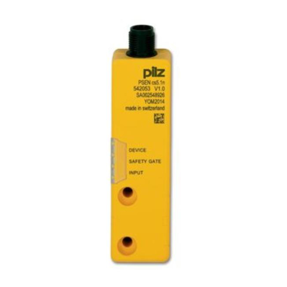
Operating distances [1] Actuator aligned to the square marking on the switch Assured operating distance: 8 mm Assured release distance: 20 mm Typical operating distance: 11 mm Typical release distance: 14 mm DEVICE SAFETY GATE INPUT Operating Manual PSEN cs6.11n 1004127-EN-03... - Page 10 Typical course of change in the holding force as the distance from the switch to the actuator increases with frontal approach holding force (N) distance (mm) Fig.: Change in the holding force for distances from 0-25 mm Operating Manual PSEN cs6.11n 1004127-EN-03...
-
Page 11: Lateral And Vertical Offset
Actuator aligned to the square marking on the switch -12 -8 -4 0 Legend [1] Hysteresis [2] Typical operating distance S [3] Typical release distance S [4] Offset in mm [5] Operating distance in mm [6] Response range [7] Status of LED Operating Manual PSEN cs6.11n 1004127-EN-03... - Page 12 8 4 0 Legend [1] Hysteresis [2] Typical operating distance S [3] Typical release distance S [4] Offset in mm [5] Operating distance in mm [6] Response range [7] Status of LED [8] Square marking Operating Manual PSEN cs6.11n 1004127-EN-03...
-
Page 13: Wiring
Function Wire colour +24 V UB brown Output, channel1 white 0 V UB blue Output, channel2 black Signal output grey The wire colour also applies for the cable available from Pilz as an accessory. Operating Manual PSEN cs6.11n 1004127-EN-03... -
Page 14: Connection To Evaluation Devices
Actuator Receiver Evaluation device Connection to Pilz evaluation devices The safety switch PSEN cs6.11n can be connected to Pilz evaluation devices, for example. Suitable Pilz evaluation devices are, for example: PNOZelog for safety gate monitoring PNOZpower for safety gate monitoring PNOZsigma for safety gate monitoring Operating Manual PSEN cs6.11n... - Page 15 The connections to two evaluation devices are shown on the following pages, by way of ex- ample: PNOZ s3 and PNOZmulti PNOZ s3 PSENcode PNOZ s3 PNOZmulti PNOZmulti PSENcode 5 Y32 Legend: Input OSSD Input OSSD Signal input Operating Manual PSEN cs6.11n 1004127-EN-03...
-
Page 16: Teaching In The Actuator
Torque setting: Please note the information provided under Technical details [ 23]. The distance between two safety switches must be maintained (see Technical details [ 23]). The distance can be undershot in certain application cases (see diagrams). Operating Manual PSEN cs6.11n 1004127-EN-03... - Page 17 Clause 7.2c of EN ISO 14119. Fig.: Seals [1]: 4 seals for actuators [2]: 2 seals for actuators [3]: 2 seals for actuators [4]: 2 seals for switches and 2 seals for actuators Operating Manual PSEN cs6.11n 1004127-EN-03...
- Page 18 4. Use a screw to fix the actuator to the mounting surface. Make sure that the actuator with the triangle marking points towards the triangle mark- ing on the sensor. 5. Do not fully tighten the second screw on the actuator. Operating Manual PSEN cs6.11n 1004127-EN-03...
-
Page 19: Use In Operating Heights Higher Than 2000 M Above Sea Level
7. Align the actuator and tighten the screws. Use in operating heights higher than 2000 m above sea level When using the PSEN cs6.11n note the reduced max. ambient temperature of +60 °C at a height of 2000 m to 4000 m. -
Page 20: Normal Mode
Display of Outputs in fault con- Check the outputs and last status last status dition switch the voltage off and then on again. Display not Wrong actuator Use the actuator PSEN definitive cs6.11 M12. green yellow Operating Manual PSEN cs6.11n 1004127-EN-03... -
Page 21: Dimensions In Mm
PSEN cs6.11n LED status Device Safety Gate Input Switch status Remedy / measure Switch doesn't start Change the switch. yellow yellow Dimensions in mm Safety switch DEVICE SAFETY GATE INPUT 26,4 Operating Manual PSEN cs6.11n 1004127-EN-03... - Page 22 PSEN cs6.11n Actuator Legend: [1] Square marking [2] Triangle marking [3] LEDs [4] Semicircle marking Operating Manual PSEN cs6.11n 1004127-EN-03...
-
Page 23: Technical Details
Lowest operating current 2 mA Utilisation category in accordance with EN 60947-1 DC-12 Times Test pulse duration, safety outputs 150 µs Switch-on delay after UB is applied Actuator typ. 30 ms Actuator max. 50 ms Operating Manual PSEN cs6.11n 1004127-EN-03... - Page 24 Protection type Housing IP66, IP67 Mechanical data Magnetic holding force between actuator and sensor 30 N Actuator 1 PSEN cs6.11 M12 Operating distances Repetition accuracy switching distances Change of operating distance with temperature changes +-0,02mm/°C Operating Manual PSEN cs6.11n 1004127-EN-03...
-
Page 25: Safety Characteristic Data
[1/h] 2015 2015 2015 Category [year] 2-ch. OSSD PL e Cat. 4 SIL CL 3 9,56E-10 – 8,51E-06 All the units used within a safety function must be considered when calculating the safety characteristic data. Operating Manual PSEN cs6.11n 1004127-EN-03... -
Page 26: Supplementary Data
2) this product must accept any interference received, including interference that may cause undesired operation. Changes or modifications made to this product not expressly approved by Pilz may void the FCC authorization to operate this equipment. NOTE: This equipment has been tested and found to comply with the limits for a Class A digital device, pursuant to Part 15 of the FCC Rules. - Page 27 630 311 10 m 630 312 20 m 630 298 30 m 630 297 PSEN cable M12-5af Angled, M12, 5-pin, socket Open cable 630 347 630 348 10 m 630 349 30 m 630 350 Operating Manual PSEN cs6.11n 1004127-EN-03...
- Page 28 European Parliament and of the Council. 2006/42/EC on machines 2014/53/EC on radio equipment The complete EC Declaration of Conformity is available on the Internet at www.pilz.com/ downloads. Representative: Norbert Fröhlich, Pilz GmbH & Co. KG, Felix-Wankel-Str. 2, 73760 Ost- fildern, Germany Operating Manual PSEN cs6.11n...
- Page 29 Back cover Support Technical support is available from Pilz round the clock. Americas Australia Scandinavia Brazil +61 3 95600621 +45 74436332 +55 11 97569-2804 Spain Canada Europe +34 938497433 +1 888-315-PILZ (315-7459) Austria Switzerland Mexico +43 1 7986263-0 +41 62 88979-30...
Need help?
Do you have a question about the PSEN cs6.11n and is the answer not in the manual?
Questions and answers