Table of Contents
Advertisement
Quick Links
Advertisement
Table of Contents

Related Manuals for Pilz PSEN cs6.21 M12/8


Summary of Contents for Pilz PSEN cs6.21 M12/8
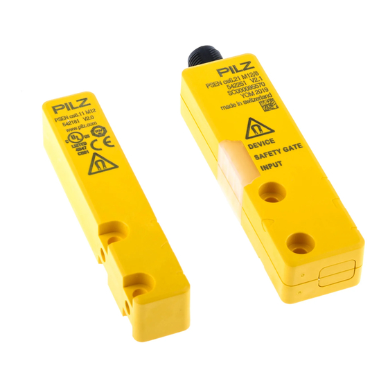
- Page 1 PSEN cs6.21 M12/8 PSEN sensor technology Operating Manual-1003426-EN-06...
- Page 2 Preface This document is the original document. All rights to this documentation are reserved by Pilz GmbH & Co. KG. Copies may be made for the user's internal purposes. Suggestions and comments for improving this documenta- tion will be gratefully received.
-
Page 3: Table Of Contents
Teaching in the actuator Installation Use in operating heights higher than 2000 m above sea level Adjustment Operation Normal mode Error display Dimensions in mm Technical details Safety characteristic data Supplementary data Radio approval Operating Manual PSEN cs6.21 M12/8 1003426-EN-06... - Page 4 Contents Order reference System Accessories EC declaration of conformity Operating Manual PSEN cs6.21 M12/8 1003426-EN-06...
-
Page 5: Introduction
PSEN cs6.21 M12/8 Introduction Validity of documentation This documentation is valid for the product PSEN cs6.21 M12/8 from Version 2.0. This operating manual explains the function and operation, describes the installation and provides guidelines on how to connect the product. -
Page 6: Safety
If installed in other environments, measures should be taken to comply with the applicable standards and directives for the respective installation site with regard to in- terference. Operating Manual PSEN cs6.21 M12/8 1003426-EN-06... -
Page 7: Safety Regulations
Are familiar with the basic regulations concerning health and safety / accident preven- tion, Have read and understood the information provided in the section entitled Safety Have a good knowledge of the generic and specialist standards applicable to the spe- cific application. Operating Manual PSEN cs6.21 M12/8 1003426-EN-06... -
Page 8: Warranty And Liability
– If the original actuators are replaced with substitute actuators, the ori- ginal actuators must be destroyed before disposal. Do not remove the connector's protective cap until you are just about to connect the unit. This will prevent potential contamination. Operating Manual PSEN cs6.21 M12/8 1003426-EN-06... -
Page 9: Unit Features
Safety input Safety input Safety out- Safety out- (without use range put 12 put 22 of the SDD) High High High High High High High High High High High High x: High or low signal Operating Manual PSEN cs6.21 M12/8 1003426-EN-06... -
Page 10: Safety Device Diagnostics
The communication of the sensors with the fieldbus module is automatically built up again with each new supply of the supply voltage. As a result, a sensor can be exchanged, e.g. when servicing, without the need for special measures. Operating Manual PSEN cs6.21 M12/8 1003426-EN-06... -
Page 11: Operating Distances
[1] Actuator aligned to the square marking on the switch Assured operating distance: 8 mm Assured release distance: 20 mm Typical operating distance: 11 mm Typical release distance: 14 mm DEVICE SAFETY GATE INPUT Operating Manual PSEN cs6.21 M12/8 1003426-EN-06... - Page 12 Typical course of change in the holding force as the distance from the switch to the actuator increases with frontal approach holding force (N) distance (mm) Fig.: Change in the holding force for distances from 0-25 mm Operating Manual PSEN cs6.21 M12/8 1003426-EN-06...
-
Page 13: Lateral And Vertical Offset
Actuator aligned to the square marking on the switch -12 -8 -4 0 Legend [1] Hysteresis [2] Typical operating distance S [3] Typical release distance S [4] Offset in mm [5] Operating distance in mm [6] Response range [7] Status of LED Operating Manual PSEN cs6.21 M12/8 1003426-EN-06... - Page 14 8 4 0 Legend [1] Hysteresis [2] Typical operating distance S [3] Typical release distance S [4] Offset in mm [5] Operating distance in mm [6] Response range [7] Status of LED [8] Square marking Operating Manual PSEN cs6.21 M12/8 1003426-EN-06...
-
Page 15: Wiring
Pin assignment, connector and cable 8-pin M12 connector Connection designation Function Wire colour Input, channel 2 white +24 VUB brown Output, channel1 green Output, channel2 yellow Signal output/diagnostic output grey Input, channel 1 pink Operating Manual PSEN cs6.21 M12/8 1003426-EN-06... -
Page 16: Connection To Evaluation Devices
0 V UB blue Diagnostics input The wire colour also applies for the cable available from Pilz as an accessory. Connection to evaluation devices Make sure that the selected evaluation device has the following property: OSSD signals are evaluated through 2 channels with feasibility monitoring... -
Page 17: Single Connection
PSEN cs6.21 M12/8 Single connection Connection diagram, single connection without SDD Actuator Receiver Evaluation device Operating Manual PSEN cs6.21 M12/8 1003426-EN-06... - Page 18 PSEN cs6.21 M12/8 Connection diagram, single connection with SDD 24 V Actuator Safety switch I1 (FS) I2 (FS) Evaluation device Fieldbus module FS: Failsafe Operating Manual PSEN cs6.21 M12/8 1003426-EN-06...
-
Page 19: Series Connection
PSEN ix2 F4 code – PSEN ix2 F8 code – PSEN Y junction M8-M12/M12 PIGTAIL – PSEN Y junction M12-M12/M12 PIGTAIL – PSEN Y junction M12 SENSOR – PSEN Y junction M12 cable channel Operating Manual PSEN cs6.21 M12/8 1003426-EN-06... - Page 20 PSEN cs6.21 M12/8 Connection diagram, series connection without SDD Actuator Receiver Control system Actuator Receiver Actuator Receiver Evaluation device Operating Manual PSEN cs6.21 M12/8 1003426-EN-06...
- Page 21 PSEN cs6.21 M12/8 Connection diagram, series connection with SDD 24 V Safety switch Actuator Safety switch Actuator Safety switch Actuator I1 (FS) I2 (FS) Evaluation device Fieldbus module FS: Failsafe ST: Standard Operating Manual PSEN cs6.21 M12/8 1003426-EN-06...
-
Page 22: Connection To Pilz Evaluation Devices
PSEN cs6.21 M12/8 Connection to Pilz evaluation devices The safety switch PSEN cs6.21 M12/8 can be connected to Pilz evaluation devices, for ex- ample. Suitable Pilz evaluation devices are, for example: PNOZelog for safety gate monitoring PNOZpower for safety gate monitoring... -
Page 23: Teaching In The Actuator
The first actuator PSEN cs6.11 M12 detected by the safety switch is automatically taught in as soon as it is brought into the response range. NOTICE No other actuator may be taught in once this actuator has been taught. Operating Manual PSEN cs6.21 M12/8 1003426-EN-06... -
Page 24: Installation
The actuator should be protected from unauthorised removal and from contamination. Close the mounting holes using the seals provided (see diagrams). The use of seals should be regarded as equivalent to using permanent fastenings in accordance with Clause 7.2c of EN ISO 14119. Operating Manual PSEN cs6.21 M12/8 1003426-EN-06... - Page 25 [1]: 4 seals for actuators [2]: 2 seals for actuators [3]: 2 seals for actuators [4]: 2 seals for switches and 2 seals for actuators Fig.: Applying the screw cover [4] on the switch Operating Manual PSEN cs6.21 M12/8 1003426-EN-06...
-
Page 26: Use In Operating Heights Higher Than 2000 M Above Sea Level
7. Align the actuator and tighten the screws. Use in operating heights higher than 2000 m above sea level When using the PSEN cs6.21 M12/8 note the reduced max. ambient temperature of +60 °C at a height of 2000 m to 4000 m. -
Page 27: Operation
[ 30]. Display not Display not Supply voltage is at Ensure the voltage supply definitive definitive the limit of the toler- corresponds to the Tech- ance range yellow nical details [ 30]. Operating Manual PSEN cs6.21 M12/8 1003426-EN-06... -
Page 28: Dimensions In Mm
Display not Wrong actuator Use the actuator PSEN definitive cs6.11 M12. green yellow Switch doesn't start Change the switch. yellow yellow Dimensions in mm Safety switch DEVICE SAFETY GATE INPUT 26,4 Operating Manual PSEN cs6.21 M12/8 1003426-EN-06... - Page 29 PSEN cs6.21 M12/8 Actuator Legend: [1] Square marking [2] Triangle marking [3] LEDs [4] Semicircle marking Operating Manual PSEN cs6.21 M12/8 1003426-EN-06...
-
Page 30: Technical Details
400 µA Voltage drop at OSSDs Conditional rated short circuit current 100 A Lowest operating current 2 mA Utilisation category in accordance with EN 60947-1 DC-12 Times Test pulse duration, safety outputs 150 µs Operating Manual PSEN cs6.21 M12/8 1003426-EN-06... - Page 31 Shock stress EN 60947-5-2 In accordance with the standard Acceleration 11 ms Duration Airgap creepage Overvoltage category Pollution degree Rated insulation voltage 75 V Rated impulse withstand voltage 1 kV Protection type Housing IP66, IP67 Operating Manual PSEN cs6.21 M12/8 1003426-EN-06...
- Page 32 Actuator dimensions 18 mm Height Width 90 mm Depth 19 mm 75 g Weight of safety switch Weight of actuator 60 g Weight 135 g Where standards are undated, the 2015-11 latest editions shall apply. Operating Manual PSEN cs6.21 M12/8 1003426-EN-06...
-
Page 33: Safety Characteristic Data
2) this product must accept any interference received, including interference that may cause undesired operation. Changes or modifications made to this product not expressly approved by Pilz may void the FCC authorization to operate this equipment. NOTE: This equipment has been tested and found to comply with the limits for a Class A digital device, pursuant to Part 15 of the FCC Rules. - Page 34 540 320 10 m 540 321 20 m 540 333 30 m 540 326 PSEN cable M12-8af Angled, M12, 8-pin, socket Open cable 540 322 540 323 10 m 540 324 30 m 540 325 Operating Manual PSEN cs6.21 M12/8 1003426-EN-06...
- Page 35 TCP for Safety Device Dia- gnostics SDD ES Profibus Fieldbus module Profibus Spring-loaded terminal 540 132 for Safety Device Dia- gnostics SDD ES Profinet Fieldbus module for Safety Spring-loaded terminal 540 138 Device Diagnostics Operating Manual PSEN cs6.21 M12/8 1003426-EN-06...
- Page 36 European Parliament and of the Council. 2006/42/EC on machines 2014/53/EC on radio equipment The complete EC Declaration of Conformity is available on the Internet at www.pilz.com/ downloads. Representative: Norbert Fröhlich, Pilz GmbH & Co. KG, Felix-Wankel-Str. 2, 73760 Ost- fildern, Germany Operating Manual PSEN cs6.21 M12/8...
Need help?
Do you have a question about the PSEN cs6.21 M12/8 and is the answer not in the manual?
Questions and answers