Table of Contents
Advertisement
Quick Links
Advertisement
Table of Contents

Related Manuals for Pilz PSEN cs6.2p


Summary of Contents for Pilz PSEN cs6.2p
- Page 1 PSEN cs6.2p PSEN sensor technology Operating Manual-1003430-EN-06...
- Page 2 Preface This document is the original document. All rights to this documentation are reserved by Pilz GmbH & Co. KG. Copies may be made for the user's internal purposes. Suggestions and comments for improving this documenta- tion will be gratefully received.
-
Page 3: Table Of Contents
Lateral and vertical offset......................Wiring ............................Important information........................ Connection to evaluation devices ..................Single connection ........................Series connection ........................Connection to Pilz evaluation devices ..................Teaching in the actuator ....................... Installation ..........................General ............................. Safety switch..........................Actuator 6.1 ..........................Actuator 6.1 low profile ...................... - Page 4 Technical details actuator ..................... Classification according to ZVEI, CB24I ................Safety characteristic data ..................... Supplementary data ......................Radio approval.......................... Order reference ........................Safety switch..........................Actuator ............................ Complete systems ........................Accessories ..........................EC declaration of conformity ....................Operating Manual PSEN cs6.2p 1003430-EN-06...
-
Page 5: Introduction
PSEN cs6.2p Introduction Validity of documentation This documentation is valid for the product PSEN cs6.2p from Version 2.0. This operating manual explains the function and operation, describes the installation and provides guidelines on how to connect the product. Using the documentation This document is intended for instruction. -
Page 6: Safety
Approved actuators: PSEN cs6.1 PSEN cs6.1 low profile glue PSEN cs6.1 low profile screw Operating Manual PSEN cs6.2p 1003430-EN-06... -
Page 7: Safety Regulations
Are familiar with the basic regulations concerning health and safety / accident prevention, Have read and understood the information provided in the section entitled Safety Have a good knowledge of the generic and specialist standards applicable to the specific application. Operating Manual PSEN cs6.2p 1003430-EN-06... -
Page 8: Warranty And Liability
Do not remove the connector's protective cap until you are just about to connect the unit. This will prevent potential contamination. Unit features Transponder technology for presence detection Pilz coding type: uniquely coded Dual-channel operation 2 safety inputs for series connection of multiple safety switches 2 safety outputs Safety Device Diagnostics (SDD) –... -
Page 9: Function Description
If this safety input switches back from low to high, while the other safety input remains high, a feasibility error is displayed and a partial operation lock is triggered: Input LED flashes yellow and Device LED flashes red Operating Manual PSEN cs6.2p 1003430-EN-06... -
Page 10: Block Diagram
– Read configuration parameters of the sensor (examples: Number of teach-in pro- cesses remaining, serial number of the sensor) – Perform actions (example: poll updated actuator name) Operating Manual PSEN cs6.2p | 10 1003430-EN-06... -
Page 11: Operating Distances
[4] Actuator PSEN cs6.1 low profile glue or PSEN cs6.1 low profile screw aligned to the square marking on the switch Assured operating distance: 5 mm Assured release distance: 20 mm Typical operating distance: 10 mm Typical release distance: 12 mm Operating Manual PSEN cs6.2p | 11 1003430-EN-06... - Page 12 – Measurement over the entire temperature range – Installed on various base materials – Taking into account product tolerances Typical operating distance S and typical release distance S – Measured at room temperature – Installed on plastic Operating Manual PSEN cs6.2p | 12 1003430-EN-06...
-
Page 13: Lateral And Vertical Offset
Legend [1] Hysteresis [2] Typical operating distance S [3] Typical release distance S [4] Offset in mm [5] Operating distance in mm [6] Response range [7] Status of LED Operating Manual PSEN cs6.2p | 13 1003430-EN-06... - Page 14 [5] Operating distance in mm [6] Response range [7] Connector on the safety switch [8] Limit of response range, position of gate hinge [9] Status of LED [10] Sensing face of the actuator, labelled with Pilz logo Operating Manual PSEN cs6.2p | 14 1003430-EN-06...
- Page 15 Alignment 1/2: Actuator PSEN cs6.1 aligned to the triangle or square marking on the switch DEVICE SAFETY GATE INPUT DEVICE SAFETY GATE INPUT 12 16 8 4 0 8 4 0 12 16 Operating Manual PSEN cs6.2p | 15 1003430-EN-06...
- Page 16 [1] Hysteresis [2] Typical operating distance S [3] Typical release distance S [4] Offset in mm [5] Operating distance in mm [6] Response range [7] Status of LED [8] Square marking [9] Triangle marking Operating Manual PSEN cs6.2p | 16 1003430-EN-06...
- Page 17 PSEN cs6.2p Vertical offset when aligning to the semicircle marking Alignment 3: Actuator PSEN cs6.1 aligned to the semicircle marking on the switch 8 4 0 8 4 0 Operating Manual PSEN cs6.2p | 17 1003430-EN-06...
- Page 18 Legend [1] Hysteresis [2] Typical operating distance S [3] Typical release distance S [4] Offset in mm [5] Operating distance in mm [6] Response range Operating Manual PSEN cs6.2p | 18 1003430-EN-06...
-
Page 19: Wiring
PSEN sg or PSEN sl) or – The faults at the safety inputs that can occur by shorts across contact will have to be excluded by suitable measures (e.g. wiring in accordance with EN 602041). Operating Manual PSEN cs6.2p | 19 1003430-EN-06... - Page 20 0 V UB blue Diagnostics input The wire colour also applies for the cable available from Pilz as an accessory. NOTICE The inputs S11 and S21 may only be used for the series connection with Pilz sensors. Operating Manual PSEN cs6.2p...
-
Page 21: Connection To Evaluation Devices
Also note the max. current (see Technical details [ 39]). Single connection Connection diagram, single connection without SDD Safety switch Actuator Evaluation device FS: Failsafe Operating Manual PSEN cs6.2p | 21 1003430-EN-06... - Page 22 PSEN cs6.2p Connection diagram, single connection with SDD 24 V Actuator Safety switch I1 (FS) I2 (FS) Evaluation device Fieldbus module FS: Failsafe Operating Manual PSEN cs6.2p | 22 1003430-EN-06...
-
Page 23: Series Connection
When making series connections using SDD, only use the following passive junctions. – PSEN ix2 F4 code – PSEN ix2 F8 code – PSEN Y junction M8-M12/M12 PIGTAIL – PSEN Y junction M8 SENSOR – PSEN Y junction M8 cable channel Operating Manual PSEN cs6.2p | 23 1003430-EN-06... - Page 24 PSEN cs6.2p Connection diagram, series connection without SDD Safety switch 1 Actuator Controller Safety switch 2 Actuator Actuator Safety switch n Evaluation device FS: Failsafe Operating Manual PSEN cs6.2p | 24 1003430-EN-06...
- Page 25 PSEN cs6.2p Connection diagram, series connection with SDD 24 V Safety switch Actuator Actuator Safety switch Actuator Safety switch I1 (FS) I2 (FS) Evaluation device Fieldbus module FS: Failsafe ST: Standard Operating Manual PSEN cs6.2p | 25 1003430-EN-06...
-
Page 26: Connection To Pilz Evaluation Devices
PSEN cs6.2p Connection to Pilz evaluation devices The safety switch PSEN cs6.2p can be connected to Pilz evaluation devices, for example. Suitable Pilz evaluation devices are, for example: PNOZelog for safety gate monitoring PNOZpower for safety gate monitoring PNOZsigma for safety gate monitoring... -
Page 27: Teaching In The Actuator
(see Operating distances [ 11]). Torque setting: Please note the information provided under Technical details [ 39]. The distance between two safety switches must be maintained (see Technical details [ 39]). Operating Manual PSEN cs6.2p | 27 1003430-EN-06... - Page 28 – Install a mechanical stop when using the response range at the semi- circle marking, to avoid unintended switching off at the limit of the re- sponse range and to prevent the maximum release distance from en- larging impermissibly by using both switching lobes. Operating Manual PSEN cs6.2p | 28 1003430-EN-06...
-
Page 29: Safety Switch
[8] Limit of response range, position of gate hinge [9] Status of LED [10] Sensing face of the actuator, labelled with Pilz logo [11] Distance from the front edge of the safety switch to the limit of the response range (position of the gate end stop) = 15.9 mm... -
Page 30: Actuator 6.1
Clean the surface with 70% isopropanol. Use lint-free paper cloths and change the pa- per cloths frequently. The adhesive surface is clean when the paper remains clean. The cleaned surfaces must be sealed immediately to prevent any new contamination by dust and fingerprints. Operating Manual PSEN cs6.2p | 30 1003430-EN-06... - Page 31 2. To seal the low profile actuators correctly, it is necessary to prepare the surface to which the actuator is to be attached. The surface must be clean, dry and free of grease. Operating Manual PSEN cs6.2p | 31 1003430-EN-06...
-
Page 32: Align Safety Switch And Actuator
The actuator should be protected from unauthorised removal and from contamination. Close the mounting holes using the seals provided. The use of seals should be regarded as equivalent to using permanent fastenings in accordance with EN ISO 14119. Operating Manual PSEN cs6.2p | 32 1003430-EN-06... - Page 33 [1] 4 seals for actuators [2] Unused seals [3] 2 seals for actuators [4] 2 seals for switches, 2 seals unused [1] [3] Fig.: Applying the screw covers [1] and [3] on the actuator Operating Manual PSEN cs6.2p | 33 1003430-EN-06...
-
Page 34: Use In Operating Heights Higher Than 2000 M Above Sea Level
3. Use the seals to close the mounting holes on the sensing face of the safety switch (see diagram, [4]). Use in operating heights higher than 2000 m above sea level When using the PSEN cs6.2p note the reduced max. ambient temperature of +60 °C at a height of 2000 m to 4000 m. Adjustment... -
Page 35: Operation
Switch status Device Ready for operation Green Safety Gate Actuator is within the response range yellow Actuator is outside the response range Input Both safety inputs are high yellow Both safety inputs are low Operating Manual PSEN cs6.2p | 35 1003430-EN-06... -
Page 36: Error Display
Display not Wrong actuator Only use an appropriate definitive actuator from Pilz. Green Yellow Switch doesn't start Change the switch. Yellow Yellow Operating Manual PSEN cs6.2p | 36 1003430-EN-06... -
Page 37: Dimensions In Mm
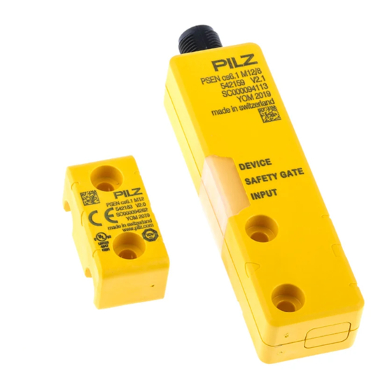
PSEN cs6.2p Dimensions in mm Safety switch DEVICE SAFETY GATE INPUT 26,4 Actuator Legend: [1] Square marking [2] Triangle marking [3] LEDs [4] Semicircle marking Operating Manual PSEN cs6.2p | 37 1003430-EN-06... - Page 38 PSEN cs6.2p Actuator PSEN cs6.1 low profile glue Actuator PSEN cs6.1 low profile screw 90° Operating Manual PSEN cs6.2p | 38 1003430-EN-06...
-
Page 39: Technical Details Safety Switch
400 µA Voltage drop at OSSDs Conditional rated short circuit current 100 A Lowest operating current 2 mA Utilisation category in accordance with EN 60947-1 DC-12 Times Test pulse duration, safety outputs 150 µs Operating Manual PSEN cs6.2p | 39 1003430-EN-06... - Page 40 In accordance with the standard EN 60068-2-27 Acceleration Duration 11 ms Airgap creepage Overvoltage category Pollution degree Rated insulation voltage 75 V Rated impulse withstand voltage 1 kV Protection type Housing IP66, IP67 Operating Manual PSEN cs6.2p | 40 1003430-EN-06...
- Page 41 PSEN cs6.1 low profile screw Assured operating distance Sao 5 mm Assured release distance Sar 20 mm Typical operating distance So 10 mm Typical release distance Sr 12 mm Typical hysteresis 2 mm Operating Manual PSEN cs6.2p | 41 1003430-EN-06...
- Page 42 PA+GF, PBT, polycarbonate Max. torque setting for fixing screws 1 Nm Dimensions Height 26,4 mm Width 97,6 mm Depth 13 mm Weight 48 g Where standards are undated, the 2015-11 latest editions shall apply. Operating Manual PSEN cs6.2p | 42 1003430-EN-06...
-
Page 43: Technical Details Actuator
Acceleration Duration 11 ms Protection type Housing IP66, IP67 Mechanical data Material Max. torque setting for fixing screws 1 Nm Dimensions Height 18 mm Width 37 mm Depth 13 mm Weight 10 g Operating Manual PSEN cs6.2p | 43 1003430-EN-06... - Page 44 Housing IP67 IP67 Mechanical data 542187 542188 Material Max. torque setting for fixing screws – 0,1 Nm Dimensions Height 3,8 mm 3,8 mm Width 18 mm 18 mm Depth 18 mm 18 mm Operating Manual PSEN cs6.2p | 44 1003430-EN-06...
-
Page 45: Classification According To Zvei, Cb24I
Max. capacitive load 1 nF Single-pole output Interfaces Source Interface Sensor Class Drain Class C1, C2 Source parameters Max. test pulse duration 150 µs Max. rated current 0,1 A Max. capacitive load 40 nF Operating Manual PSEN cs6.2p | 45 1003430-EN-06... -
Page 46: Safety Characteristic Data
A safety function's SIL/PL values are not identical to the SIL/PL values of the units that are used and may be different. We recommend that you use the PAScal software tool to calculate the safety function's SIL/PL values. Operating Manual PSEN cs6.2p | 46 1003430-EN-06... -
Page 47: Supplementary Data
2) this product must accept any interference received, including interference that may cause undesired operation. Changes or modifications made to this product not expressly approved by Pilz may void the FCC authorization to operate this equipment. NOTE: This equipment has been tested and found to comply with the limits for a Class A digital device, pursuant to Part 15 of the FCC Rules. -
Page 48: Accessories
PSEN Y junction M8 cable M8, 8‑pin, pin M8, 8‑pin, socket 540 318 channel 8‑pin, socket PSEN Y junction M8-M12/ M12, 8-pin, socket M12, 8‑pin, pin 540 337 M12 PIGTAIL 8‑pin, socket Operating Manual PSEN cs6.2p | 48 1003430-EN-06... -
Page 49: Ec Declaration Of Conformity
European Parliament and of the Council. 2006/42/EC on machines 2014/53/EC on radio equipment The complete EC Declaration of Conformity is available on the Internet at www.pilz.com/ downloads. Representative: Norbert Fröhlich, Pilz GmbH & Co. KG, Felix-Wankel-Str. 2, 73760 Ost- fildern, Germany Operating Manual PSEN cs6.2p... - Page 50 We are represented internationally. Please refer to our homepage www.pilz.com for further details or contact our headquarters. Headquarters: Pilz GmbH & Co. KG, Felix-Wankel-Straße 2, 73760 Ostfildern, Germany Telephone: +49 711 3409-0, Telefax: +49 711 3409-133, E-Mail: info@pilz.com, Internet: www.pilz.com...
Need help?
Do you have a question about the PSEN cs6.2p and is the answer not in the manual?
Questions and answers