Table of Contents
Advertisement
Quick Links
Advertisement
Table of Contents

Related Manuals for Pilz PSEN cs4.1a


Summary of Contents for Pilz PSEN cs4.1a
- Page 1 PSEN cs4.1a/b PSEN sensor technology Operating Manual-1003292-EN-07...
- Page 2 Preface This document is the original document. All rights to this documentation are reserved by Pilz GmbH & Co. KG. Copies may be made for the user's internal purposes. Suggestions and comments for improving this documenta- tion will be gratefully received.
-
Page 3: Table Of Contents
Function description Safety Device Diagnostics Operating distances Lateral and vertical offset Wiring Connection to evaluation devices Single connection Series connection Connection to Pilz evaluation devices Teaching in the actuator Installation Adjustment Operation Dimensions in mm Safety switch Actuator Operating Manual PSEN cs4.1a/b... - Page 4 Contents Technical details safety switch Technical details actuator Safety characteristic data Supplementary data Radio approval Order reference Safety switch Actuator Complete systems Accessories EC declaration of conformity Operating Manual PSEN cs4.1a/b 1003292-EN-07...
-
Page 5: Introduction
PSEN cs4.1a/b Introduction Validity of documentation This documentation is valid for the product PSEN cs4.1a/b from Version 2.0. This operating manual explains the function and operation, describes the installation and provides guidelines on how to connect the product. Using the documentation This document is intended for instruction. -
Page 6: Safety
If installed in other environments, measures should be taken to comply with the applicable standards and directives for the respective installation site with regard to in- terference. Operating Manual PSEN cs4.1a/b 1003292-EN-07... -
Page 7: Safety Regulations
Are familiar with the basic regulations concerning health and safety / accident preven- tion, Have read and understood the information provided in the section entitled Safety Have a good knowledge of the generic and specialist standards applicable to the spe- cific application. Operating Manual PSEN cs4.1a/b 1003292-EN-07... -
Page 8: Warranty And Liability
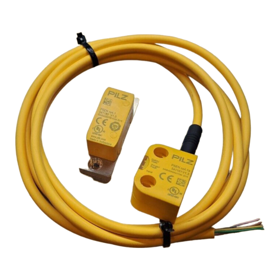
– If the original actuators are replaced with substitute actuators, the ori- ginal actuators must be destroyed before disposal. Unit features Transponder technology for presence detection Pilz coding type: fully coded Dual-channel operation 2 safety inputs for series connection of multiple safety switches 2 safety outputs Safety Device Diagnostics (SDD) –... - Page 9 Signal output/diagnostic output Y32 for Safety Device Diagnostics LED display for: – State of the actuator – State of the inputs – Supply voltage/fault 1 direction of actuation Connection types: – PSEN cs4.1a: Cable, 5 m – PSEN cs4.1b: Cable, 10 m Operating Manual PSEN cs4.1a/b 1003292-EN-07...
-
Page 10: Function Description
If no fieldbus module of the SDD is used, the diagnostic input Y1 is not used. Signal output/diagnostic output Y32 The status of the actuator is output. If a fieldbus module of the SDD is used, the signal output/diagnostic output for the writing of data is activated. Operating Manual PSEN cs4.1a/b 1003292-EN-07... -
Page 11: Safety Device Diagnostics
This prevents wiring errors and an expansion or reduction of the sensors is possible without the need to change existing wiring. – Wiring in accordance with IP20: Rapid installation in the control cabined is enabled. Operating Manual PSEN cs4.1a/b 1003292-EN-07... -
Page 12: Operating Distances
Min. operating distance omin Assured release distance The offset-independent values for the switching distances are included in the Technical details [ 27]. Lateral and vertical offset Fig.: Safety switches PSEN cs4.1a/b with actuator PSEN cs4.1 Operating Manual PSEN cs4.1a/b 1003292-EN-07... -
Page 13: Wiring
PSEN cs4.1a/b -10 -8 -6 -4 0 12 14 16 Fig.: Safety switches PSEN cs4.1a/b with actuator PSEN cs2.1 Legend [1] Hysteresis [2] Typical operating distance S [3] Typical release distance S [4] Offset in mm [5] Operating distance in mm... -
Page 14: Connection To Evaluation Devices
0 V UB blue Diagnostics input The wire colour also applies for the cable available from Pilz as an accessory. Connection to evaluation devices Make sure that the selected evaluation device has the following property: OSSD signals are evaluated through 2 channels with feasibility monitoring... -
Page 15: Single Connection
PSEN cs4.1a/b Single connection Connection diagram, single connection without SDD Actuator Receiver Evaluation device Operating Manual PSEN cs4.1a/b 1003292-EN-07... - Page 16 PSEN cs4.1a/b Connection diagram, single connection with SDD 24 V Actuator Safety switch I1 (FS) I2 (FS) Evaluation device Fieldbus module FS: Failsafe Operating Manual PSEN cs4.1a/b 1003292-EN-07...
-
Page 17: Series Connection
PSEN Y junction M8-M12/M12 PIGTAIL – PSEN Y junction M12-M12/M12 PIGTAIL – PSEN Y junction M12 SENSOR – PSEN Y junction M12 cable channel – PSEN Y junction M8 SENSOR – PSEN Y junction M8 cable channel Operating Manual PSEN cs4.1a/b 1003292-EN-07... - Page 18 PSEN cs4.1a/b Connection diagram, series connection without SDD Actuator Receiver Control system Actuator Receiver Actuator Receiver Evaluation device Operating Manual PSEN cs4.1a/b 1003292-EN-07...
- Page 19 PSEN cs4.1a/b Connection diagram, series connection with SDD 24 V Safety switch Actuator Safety switch Actuator Safety switch Actuator I1 (FS) I2 (FS) Evaluation device Fieldbus module FS: Failsafe ST: Standard Operating Manual PSEN cs4.1a/b 1003292-EN-07...
-
Page 20: Connection To Pilz Evaluation Devices
PSEN cs4.1a/b Connection to Pilz evaluation devices The safety switch PSEN cs4.1a/b can be connected to Pilz evaluation devices, for example. Suitable Pilz evaluation devices are, for example: PNOZelog for safety gate monitoring PNOZpower for safety gate monitoring PNOZsigma for safety gate monitoring... -
Page 21: Teaching In The Actuator
1. NOTICE – The actuator must not be removed during the learning procedure. – It is no loner possible to reteach his actuator on the same safety switch. Operating Manual PSEN cs4.1a/b 1003292-EN-07... -
Page 22: Installation
Make sure that the bend protection is not damaged. Such damage can cause the whole product to fail. Procedure: Please note: Installation is identical for all combinations of safety switch and approved actuators. The diagram of the actuators PSEN cs4.1 and PSEN cs2.1 represents the other approved actu- ators. Operating Manual PSEN cs4.1a/b 1003292-EN-07... - Page 23 Parallel assembly Orthogonal assembly 5. Align the safety switch and tighten the screws. 6. Close the mounting holes using the seals provided (see diagram). Use the seals [1] for UL approval or [4] without UL approval. Operating Manual PSEN cs4.1a/b 1003292-EN-07...
- Page 24 2. Use two screws to fix the safety switch in place. Do not fully tighten the 2nd screw on the safety switch. 3. Attach the screws for the actuator, leaving a distance of 3 … 6 mm between the screw head and plate. Operating Manual PSEN cs4.1a/b 1003292-EN-07...
-
Page 25: Adjustment
"Power/Fault" LED lights up red: Error message Remedy: Rectify fault and interrupt power supply. Please note the different times for The switch-on delay after UB is applied The recovery time of the sensor and evaluation device. Operating Manual PSEN cs4.1a/b 1003292-EN-07... -
Page 26: Dimensions In Mm
PSEN cs4.1a/b Dimensions in mm Safety switch 26,4 Actuator Fig.: Actuator PSEN cs2.1 Operating Manual PSEN cs4.1a/b 1003292-EN-07... -
Page 27: Technical Details Safety Switch
400 nF 400 nF PNOZmulti, PNOZelog, PSS 400 nF 400 nF Max. inrush current impulse Current pulse, A1 0,58 A 0,58 A Pulse duration, A1 1 ms 1 ms No-load current 20 mA 20 mA Operating Manual PSEN cs4.1a/b 1003292-EN-07... - Page 28 In accordance with the standard EN 60068-2-14 EN 60068-2-14 Temperature range -25 - 70 °C -25 - 70 °C Storage temperature In accordance with the standard EN 60068-2-1/-2 EN 60068-2-1/-2 Temperature range -25 - 70 °C -25 - 70 °C Operating Manual PSEN cs4.1a/b 1003292-EN-07...
- Page 29 33 mm 33 mm Typical release distance Sr 29 mm 29 mm Repetition accuracy switching distances 10 % 10 % Change of operating distance with temperature changes +-0,1mm/°C +-0,1mm/°C Typ. Hysteresis 3 mm 3 mm Operating Manual PSEN cs4.1a/b 1003292-EN-07...
-
Page 30: Technical Details Actuator
93 % r. h. at 40 °C EN 60947-5-3 EN 60947-5-3 Vibration In accordance with the standard EN 60947-5-2 EN 60947-5-2 Frequency 10 - 55 Hz 10 - 55 Hz Amplitude 1 mm 0,35 mm Operating Manual PSEN cs4.1a/b 1003292-EN-07... -
Page 31: Safety Characteristic Data
A safety function's SIL/PL values are not identical to the SIL/PL values of the units that are used and may be different. We recommend that you use the PAScal software tool to calculate the safety function's SIL/PL values. Operating Manual PSEN cs4.1a/b 1003292-EN-07... -
Page 32: Supplementary Data
2) this product must accept any interference received, including interference that may cause undesired operation. Changes or modifications made to this product not expressly approved by Pilz may void the FCC authorization to operate this equipment. NOTE: This equipment has been tested and found to comply with the limits for a Class A digital device, pursuant to Part 15 of the FCC Rules. -
Page 33: Accessories
SENSOR pin, socket PSEN Y junction M12 M12, 8‑pin, pin M12, 8-pin, socket M12, 8- 540 316 cable channel pin, socket PSEN T junction M12 M12, 8-pin, socket M12, 8‑pin, pin 540 331 4‑pin, pin Operating Manual PSEN cs4.1a/b 1003292-EN-07... -
Page 34: Ec Declaration Of Conformity
European Parliament and of the Council. 2006/42/EC on machines 2014/53/EC on radio equipment The complete EC Declaration of Conformity is available on the Internet at www.pilz.com/ downloads. Representative: Norbert Fröhlich, Pilz GmbH & Co. KG, Felix-Wankel-Str. 2, 73760 Ost- fildern, Germany Operating Manual PSEN cs4.1a/b... - Page 35 Back cover Support Technical support is available from Pilz round the clock. Americas Australia Scandinavia Brazil +61 3 95600621 +45 74436332 +55 11 97569-2804 Spain Canada Europe +34 938497433 +1 888-315-PILZ (315-7459) Austria Switzerland Mexico +43 1 7986263-0 +41 62 88979-30...
Need help?
Do you have a question about the PSEN cs4.1a and is the answer not in the manual?
Questions and answers