Table of Contents
Advertisement
Quick Links
Advertisement
Table of Contents

Subscribe to Our Youtube Channel
Related Manuals for Pilz PSEN cs6.21n


Summary of Contents for Pilz PSEN cs6.21n
- Page 1 PSEN cs6.21n PSEN sensor technology Operating Manual-1004128-EN-03...
- Page 2 Preface This document is the original document. All rights to this documentation are reserved by Pilz GmbH & Co. KG. Copies may be made for the user's internal purposes. Suggestions and comments for improving this documenta- tion will be gratefully received.
-
Page 3: Table Of Contents
Operating distances Lateral and vertical offset Wiring Pin assignment, connector and cable Connection to evaluation devices Single connection Connection to Pilz evaluation devices Teaching in the actuator Installation Use in operating heights higher than 2000 m above sea level Adjustment Operation... - Page 4 Contents Order reference System Accessories EC declaration of conformity Operating Manual PSEN cs6.21n 1004128-EN-03...
-
Page 5: Introduction
PSEN cs6.21n Introduction Validity of documentation This documentation is valid for the product PSEN cs6.21n. It is valid until new documenta- tion is published. This operating manual explains the function and operation, describes the installation and provides guidelines on how to connect the product. -
Page 6: Safety
If installed in other environments, measures should be taken to comply with the applicable standards and directives for the respective installation site with regard to in- terference. Operating Manual PSEN cs6.21n 1004128-EN-03... -
Page 7: Safety Regulations
In safety-related applications, please comply with the mission time T in the safety-re- lated characteristic data. When decommissioning, please comply with local regulations regarding the disposal of electronic devices (e.g. Electrical and Electronic Equipment Act). Operating Manual PSEN cs6.21n 1004128-EN-03... -
Page 8: For Your Safety
Do not remove the connector's protective cap until you are just about to connect the unit. This will prevent potential contamination. Unit features Transponder technology for presence detection Pilz coding type: uniquely coded Dual-channel operation 2 safety outputs 1 signal output... -
Page 9: Function Description
Operating distances [1] Actuator aligned to the square marking on the switch Assured operating distance: 8 mm Assured release distance: 20 mm Typical operating distance: 11 mm Typical release distance: 14 mm DEVICE SAFETY GATE INPUT Operating Manual PSEN cs6.21n 1004128-EN-03... - Page 10 Typical course of change in the holding force as the distance from the switch to the actuator increases with frontal approach holding force (N) distance (mm) Fig.: Change in the holding force for distances from 0-25 mm Operating Manual PSEN cs6.21n 1004128-EN-03...
-
Page 11: Lateral And Vertical Offset
Actuator aligned to the square marking on the switch -12 -8 -4 0 Legend [1] Hysteresis [2] Typical operating distance S [3] Typical release distance S [4] Offset in mm [5] Operating distance in mm [6] Response range [7] Status of LED Operating Manual PSEN cs6.21n 1004128-EN-03... -
Page 12: Wiring
The power supply must meet the regulations for extra low voltages with protective sep- aration (SELV, PELV). The inputs and outputs of the safety switch must have a protective separation to voltages over 60 VDC. Operating Manual PSEN cs6.21n 1004128-EN-03... -
Page 13: Pin Assignment, Connector And Cable
Output, channel2 black Signal output grey The wire colour also applies for the cable available from Pilz as an accessory. Connection to evaluation devices Make sure that the selected evaluation device has the following properties: 2-channel with feasibility monitoring OSSD signals are evaluated... -
Page 14: Connection To Pilz Evaluation Devices
Actuator Receiver Evaluation device Connection to Pilz evaluation devices The safety switch PSEN cs6.21n can be connected to Pilz evaluation devices, for example. Suitable Pilz evaluation devices are, for example: PNOZelog for safety gate monitoring PNOZpower for safety gate monitoring... -
Page 15: Teaching In The Actuator
The first actuator PSEN cs6.11 M12 detected by the safety switch is automatically taught in as soon as it is brought into the response range. NOTICE No other actuator may be taught in once this actuator has been taught. Operating Manual PSEN cs6.21n 1004128-EN-03... -
Page 16: Installation
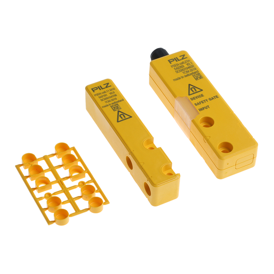
The actuator should be protected from unauthorised removal and from contamination. Close the mounting holes using the seals provided (see diagrams). The use of seals should be regarded as equivalent to using permanent fastenings in accordance with Clause 7.2c of EN ISO 14119. Operating Manual PSEN cs6.21n 1004128-EN-03... - Page 17 Fig.: Seals [1]: 4 seals for actuators [2]: 2 seals for actuators [3]: 2 seals for actuators [4]: 2 seals for switches and 2 seals for actuators Fig.: Applying the screw cover [4] on the switch Operating Manual PSEN cs6.21n 1004128-EN-03...
-
Page 18: Use In Operating Heights Higher Than 2000 M Above Sea Level
7. Align the actuator and tighten the screws. Use in operating heights higher than 2000 m above sea level When using the PSEN cs6.21n note the reduced max. ambient temperature of +60 °C at a height of 2000 m to 4000 m. -
Page 19: Operation
[ 22]. Display not Display not Supply voltage is at Ensure the voltage supply definitive definitive the limit of the toler- corresponds to the Tech- ance range yellow nical details [ 22]. Operating Manual PSEN cs6.21n 1004128-EN-03... -
Page 20: Dimensions In Mm
Display not Wrong actuator Use the actuator PSEN definitive cs6.11 M12. green yellow Switch doesn't start Change the switch. yellow yellow Dimensions in mm Safety switch DEVICE SAFETY GATE INPUT 26,4 Operating Manual PSEN cs6.21n 1004128-EN-03... - Page 21 PSEN cs6.21n Actuator Legend: [1] Square marking [2] Triangle marking [3] LEDs [4] Semicircle marking Operating Manual PSEN cs6.21n 1004128-EN-03...
-
Page 22: Technical Details
Lowest operating current 2 mA Utilisation category in accordance with EN 60947-1 DC-12 Times Test pulse duration, safety outputs 150 µs Switch-on delay after UB is applied Actuator typ. 30 ms Actuator max. 50 ms Operating Manual PSEN cs6.21n 1004128-EN-03... - Page 23 Protection type IP66, IP67 Housing Mechanical data Magnetic holding force between actuator and sensor 30 N Actuator 1 PSEN cs6.11 M12 Operating distances Repetition accuracy switching distances Change of operating distance with temperature changes +-0,02mm/°C Operating Manual PSEN cs6.21n 1004128-EN-03...
-
Page 24: Safety Characteristic Data
[1/h] 2015 2015 2015 Category [year] 2-ch. OSSD PL e Cat. 4 SIL CL 3 9,56E-10 8,51E-06 – All the units used within a safety function must be considered when calculating the safety characteristic data. Operating Manual PSEN cs6.21n 1004128-EN-03... -
Page 25: Supplementary Data
2) this product must accept any interference received, including interference that may cause undesired operation. Changes or modifications made to this product not expressly approved by Pilz may void the FCC authorization to operate this equipment. NOTE: This equipment has been tested and found to comply with the limits for a Class A digital device, pursuant to Part 15 of the FCC Rules. - Page 26 630 311 10 m 630 312 20 m 630 298 30 m 630 297 PSEN cable M12-5af Angled, M12, 5-pin, socket Open cable 630 347 630 348 10 m 630 349 30 m 630 350 Operating Manual PSEN cs6.21n 1004128-EN-03...
- Page 27 European Parliament and of the Council. 2006/42/EC on machines 2014/53/EC on radio equipment The complete EC Declaration of Conformity is available on the Internet at www.pilz.com/ downloads. Representative: Norbert Fröhlich, Pilz GmbH & Co. KG, Felix-Wankel-Str. 2, 73760 Ost- fildern, Germany Operating Manual PSEN cs6.21n...
Need help?
Do you have a question about the PSEN cs6.21n and is the answer not in the manual?
Questions and answers