Pilz PSEN cs1.19n Operating Manual
Hide thumbs
Also See for PSEN cs1.19n:
- Operating instructions manual (14 pages) ,
- Operating manual (25 pages)
Table of Contents
Advertisement
Quick Links
Advertisement
Table of Contents

Subscribe to Our Youtube Channel
Related Manuals for Pilz PSEN cs1.19n


Summary of Contents for Pilz PSEN cs1.19n
- Page 1 PSEN cs1.19n PSEN sensor technology Operating Manual-1003269-EN-04...
- Page 2 Preface This document is a translation of the original document. All rights to this documentation are reserved by Pilz GmbH & Co. KG. Copies may be made for internal purposes. Suggestions and comments for improving this documentation will be gratefully received.
-
Page 3: Table Of Contents
Pin assignment, connector and cable Connection to evaluation devices Teaching in the actuator Installation Adjustment Operation Error display through flashing codes Dimensions in mm Technical details Safety characteristic data Supplementary data Radio approval Order reference System Accessories Operating Manual PSEN cs1.19n 1003269-EN-04... - Page 4 Contents EC declaration of conformity Operating Manual PSEN cs1.19n 1003269-EN-04...
-
Page 5: Introduction
PSEN cs1.19n Introduction Validity of documentation This documentation is valid for the product PSEN cs1.19n. It is valid until new documenta- tion is published. This operating manual explains the function and operation, describes the installation and provides guidelines on how to connect the product. -
Page 6: Safety
If installed in other environments, measures should be taken to comply with the applicable standards and directives for the respective installation site with regard to in- terference. Operating Manual PSEN cs1.19n 1003269-EN-04... -
Page 7: Safety Regulations
In safety-related applications, please comply with the mission time T in the safety-re- lated characteristic data. When decommissioning, please comply with local regulations regarding the disposal of electronic devices (e.g. Electrical and Electronic Equipment Act). Operating Manual PSEN cs1.19n 1003269-EN-04... -
Page 8: For Your Safety
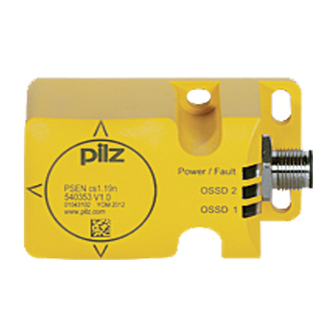
5-pin M12 male connector Function description The safety outputs may have a high or low signal, depending on the position of the actu- ator. In a safe condition there is a low signal at the safety outputs. Operating Manual PSEN cs1.19n 1003269-EN-04... -
Page 9: Block Diagram
A1 A2 Actuator OSSD1 Actuator Receiver OSSD1&2 Power Actuator OSSD2 12 22 Operating distances Legend: Assured operating distance: 15 mm Typical operating distance: 21 mm Typical release distance: 24 mm Assured release distance: 40 mm Operating Manual PSEN cs1.19n 1003269-EN-04... -
Page 10: Lateral And Vertical Offset
Lateral offset Vertical offset 0 10 20 0 10 20 Legend [1] Hysteresis [2] Typical operating distance S [3] Typical release distance S [4] Offset in mm [5] Operating distance in mm [6] Response range Operating Manual PSEN cs1.19n 1003269-EN-04... -
Page 11: Distance Between Actuators
The supply voltage to the safety switch must be protected with a 2 A to 4 A quick-acting fuse. Ensure the wiring and EMC requirements of IEC 60204-1 are met. Operating Manual PSEN cs1.19n 1003269-EN-04... -
Page 12: Pin Assignment, Connector And Cable
Black Do not connect Grey The wire colour also applies for the cable available from Pilz as an accessory. Connection to evaluation devices Make sure that the selected evaluation device has the following property: OSSD signals are evaluated through 2 channels with feasibility monitoring... - Page 13 PSEN cs1.19n Suitable Pilz evaluation devices are, for example: PNOZelog for safety gate monitoring PNOZpower for safety gate monitoring PNOZsigma for safety gate monitoring PNOZ X for safety gate monitoring PNOZmulti for safety gate monitoring Configure the switch in the PNOZmulti Configurator with switch type 3.
-
Page 14: Teaching In The Actuator
Legend I0 Input OSSD I1 Input OSSD Teaching in the actuator Any Pilz actuator PSEN cs1.19) is detected as soon as it is brought into the response range. Installation CAUTION! The unit's properties may be affected if installed in an environment contain- ing electrically or magnetically conductive material. -
Page 15: Adjustment
Operating distances [ Lateral and vertical offset [ 10]). Operation NOTICE The safety function should be checked after initial commissioning and each time the plant/machine is changed. The safety functions may only be checked by qualified personnel. Operating Manual PSEN cs1.19n 1003269-EN-04... -
Page 16: Error Display Through Flashing Codes
Flash frequency of the "OSSD1" or "OSSD2" LED Meaning of flash frequency: Flash frequency Meaning 3 times, short Code for error message Once, for one second each Code for 1st digit 4 times, for one second each Code for 2nd digit Operating Manual PSEN cs1.19n 1003269-EN-04... - Page 17 3x short – 14x long – 3x Wiring error Rectify wiring error short 3x short – 15x long – 3x Wiring error Rectify wiring error short Other flashing codes signal an internal error. Remedy: Change device. Operating Manual PSEN cs1.19n 1003269-EN-04...
-
Page 18: Dimensions In Mm
Pilz coding type Coded Coded Coded Transponder 540303 540304 540305 122 kHz - 128 kHz 122 kHz - 128 kHz 122 kHz - 128 kHz Frequency band Max. transmitter output 7 dBm 7 dBm 7 dBm Operating Manual PSEN cs1.19n 1003269-EN-04... - Page 19 Actuator typ. 30 ms 30 ms 30 ms Actuator max. 260 ms 260 ms 260 ms Supply interruption before de-energisation 20 ms 20 ms 20 ms Simultaneity, channel 1 and 2 max. ∞ ∞ ∞ Operating Manual PSEN cs1.19n 1003269-EN-04...
- Page 20 40 mm 40 mm Max. approach speed 80 mm/s 80 mm/s 80 mm/s Min. time difference between the approach of the actuators 0,5 s 0,5 s 0,5 s Actuator 1 PSEN cs1.19 PSEN cs1.19 PSEN cs1.19 Operating Manual PSEN cs1.19n 1003269-EN-04...
-
Page 21: Safety Characteristic Data
Where standards are undated, the 2014-10 latest editions shall apply. Safety characteristic data The max. safety level that can be achieved depends on the number of actuators used. Dia- gnostics must be performed to achieve a higher safety level. Operating Manual PSEN cs1.19n 1003269-EN-04... - Page 22 1. Actuator OSSD1 is detected 2. No actuator in the response range 3. Actuator OSSD2 is detected If these states are not run through within the specified time, the programmable safety sys- tem switches off the turntable. Operating Manual PSEN cs1.19n 1003269-EN-04...
-
Page 23: Supplementary Data
2) this product must accept any interference received, including interference that may cause undesired operation. Changes or modifications made to this product not expressly approved by Pilz may void the FCC authorization to operate this equipment. NOTE: This equipment has been tested and found to comply with the limits for a Class A digital device, pursuant to Part 15 of the FCC Rules. - Page 24 European Parliament and of the Council. The complete EC Declaration of Conformity is available on the Internet at www.pilz.com/downloads. Representative: Norbert Fröhlich, Pilz GmbH & Co. KG, Felix-Wankel-Str. 2, 73760 Ost- fildern, Germany Operating Manual PSEN cs1.19n...
- Page 25 Back cover Support Technical support is available from Pilz round the clock. Americas Australia Scandinavia Brazil +61 3 95600621 +45 74436332 +55 11 97569-2804 Spain Canada Europe +34 938497433 +1 888-315-PILZ (315-7459) Austria Switzerland +41 62 88979-30 Mexico +43 1 7986263-0...
Need help?
Do you have a question about the PSEN cs1.19n and is the answer not in the manual?
Questions and answers